WAVESTREAM JNB-KAM050-HS00 User manual

December 2007 Page 1 90-005-0003 Rev X01
50 Watt
Ka-band
Grid Amplifier™
BUC
User Manual

50 Watt Ka Feedmount BUC User Manual
December 2007 Page 2 90-005-0003 Rev X01
About This Handbook
This document describes Wavestream’s 50 Watt Ka-band Grid Amplifier™
Block Upconverter (BUC) herein referred to as “the Unit”.
Updated documentation may be available on our website at
www.wavestream.com or from Wavestream’s sales group
This User Manual covers installation and configuration of the 50W Ka-band
Grid Amplifier BUC, models JNB-KAM050-HS00 and JNB-KAM050HE00.
Separate manuals cover other Wavestream products.
Notices
Wavestream document 90-005-0003
Copyright © 2007, Wavestream Corporation. All rights reserved.
WavestreamTM, Spatial Power AdvantageTM, PowerstreamTM, Grid AmplifierTM
and the Wavestream logo are trademarks of the Wavestream Corporation. All
other trademarks are properties of their respective owners.
The information provided in this User Manual is being provided by
Wavestream Corporation as a service to our customers. Although every effort
has been made to verify the completeness and accuracy of the information
contained in this manual, due to the highly technical nature of the material,
and the dynamic nature of the satellite communications, Wavestream cannot
be responsible for any errors and omissions.

50 Watt Ka Feedmount BUC User Manual
December 2007 Page 3 90-005-0003 Rev X01
CONTENTS
INTRODUCTION .................................................................................................5
SAFETY...............................................................................................................8
SYSTEM DESCRIPTION...................................................................................12
SPATIAL POWER COMBINING................................................................................................... 12
INTERFACES.................................................................................................................................... 14
“IF /REF IN”CONNECTOR (J1) .................................................................................................. 14
“RF OUT”CONNECTOR (J2)....................................................................................................... 14
“120VAC IN”CONNECTOR (J3).................................................................................................. 14
Prime Power Interface Pinout:........................................................................................... 15
MONITOR AND CONTROL INTERFACE (J4)................................................................................. 15
Monitor and Control Interface Pinout:............................................................................. 16
GROUND STUD.............................................................................................................................. 17
MOUNTING INTERFACE ............................................................................................................... 17
OUTLINE DRAWINGS.................................................................................................................... 18
ADDITIONAL INFORMATION..................................................................................................... 20
CONNECTING AND CONFIGURING THE UNIT..............................................21
UNPACK THE UNIT:....................................................................................................................... 21
INSPECT INTERFACES ................................................................................................................. 22
PERFORM CONTINUITY CHECK ON THE CABLES.............................................................. 22
INSTALL THE UNIT........................................................................................................................ 22
TROUBLESHOOTING ......................................................................................24
TECHNICAL SPECIFICATIONS.......................................................................25
SPECIFICATIONS FOR GBE-300310-50-NW-AC....................................................................... 25
RF OUTPUT .................................................................................................................................. 25
IF INPUT ....................................................................................................................................... 26
INTERFACES ................................................................................................................................. 26
ENVIRONMENTAL SPECIFICATIONS ............................................................................................ 26
MECHANICAL SPECIFICATIONS................................................................................................... 27
POWER SPECIFICATIONS ............................................................................................................. 27

December 2007 Page 4 90-005-0003 Rev X01
50 Watt Ka Feedmount BUC User Manual
MAINTENANCE ................................................................................................28
FAN ASSEMBLY REPLACEMENT PROCEDURE.................................................................... 28
TOOLS REQUIRED ........................................................................................................................ 28
PROCEDURE ................................................................................................................................. 28
SERIAL M&C PROTOCOL...............................................................................29

50 Watt Ka Feedmount BUC User Manual
December 2007 Page 5 90-005-0003 Rev X01
INTRODUCTION
This User Manual provides
information and instructions for
installation and operation of
Wavestream equipment.
This User Manual is intended for use
by trained field technicians or
system engineers responsible for
satellite networks.
Updates to this User Manual may be
published. Access current versions
of this and other Wavestream
documentation by contacting
This section includes:
•Introduction
•Warranty information on the
Wavestream equipment.
•Instructions for getting
technical support for
Wavestream equipment.
This User Manual is for the Wavestream GBE-300310-50-NW-AC, a Ka-Band Grid
Amplifier Block Up Converter (BUC), herein referred to as “the Unit”. The Unit
receives an L-Band input (1000-2000MHz) and transmits a 50 Watt Ka-Band output
(30.0-31.0GHz).
The Unit comes in a single weatherized housing rated for indoor or outdoor use. It
has an N-Type input and a WR28 waveguide output, a 120VAC Power input and a
Monitor and Control connector. The Monitor and Control functions allow the user to
enable and disable the internal amplifiers without shutting off the power supplies as
well as to monitor the status of the Unit.
Warranty
The Wavestream warranty is defined in the Terms and Conditions of Sale that
accompanied the quotation and purchase order. In the event that the Unit
needs to be returned to Wavestream for repair, contact your customer service
representative at Wavestream. If you purchased this Unit from a distributor,
follow the distributor’s RMA process.
1

December 2007 Page 6 90-005-0003 Rev X01
50 Watt Ka Feedmount BUC User Manual
The warranty does not apply to any defect, failure or damage caused by
improper use or inadequate or improper maintenance and care.
Not withstanding the Warranty defined in the Terms and Conditions
of Sale, Wavestream is not obliged to furnish service under this
warranty:
•to repair damage resulting from attempts by personnel other than
Wavestream to repair, or service the product
•to repair any damage or malfunction caused by the use of non-
standard ancillary equipment
•to service a product that has been modified or integrated with other
products if this modification has not been approved previously in
writing by Wavestream
OPENING OR REMOVING ANY COMPONENT OR SEALED AREA (WITH THE
EXCEPTION OF THE FAN ASSEMBLY) WILL IMMEDIATELY VOID THE
WARRANTY
Technical Support
In the event you need technical information or operation support beyond the
scope of this User Manual, contact Wavestream support at
Equipment Service
Under all circumstances, contact Wavestream or your distributor for service.
A replacement fan assembly can be purchased from Wavestream.
With the exception of replacing the fans, do not attempt to service the
equipment yourself.
Safety Tip: Opening or removing the cover of the Unit may
expose you to dangerous voltages, high power RF energy or
other hazards as well as void your warranty.
!

December 2007 Page 7 90-005-0003 Rev X01
50 Watt Ka Feedmount BUC User Manual
Notice
For the proper operation of this equipment and/or all parts thereof, the
instructions in this guide must be strictly and explicitly followed. All of the
contents of this guide must be fully read and understood prior to operating
any of the equipment or parts thereof.
Failure to completely read and fully understand and follow all of the contents
of this guide prior to operating this equipment, or parts thereof, may result in
damage to the equipment or parts, and to any persons operating the same.
Wavestream does not assume any liability arising out of the application or use
of any products, component parts, circuits, software, or firmware described
herein. Wavestream further does not convey any license under its patent,
trademark, copyright or common-law rights nor the similar rights of others.
Wavestream further reserves the right to make any changes in any products,
or parts thereof, described herein without notice.
Caution: This equipment generates, uses, and radiates radio
frequency energy. This can present a safety hazard if not
handled safely per the precautions identified in Section 2.
!

50 Watt Ka Feedmount BUC User Manual
December 2007 Page 8 90-005-0003 Rev X01
SAFETY
This Unit contains delicate
electronics, electrical components
and high radiated RF power.
Follow all safety precautions in
this section when the Unit is in
operation.
Carefully read and follow all
safety, use, and operating
instructions before operating the
Unit. Retain these instructions for
future reference.
This section includes:
•Safety considerations for use of
the Unit.
Safety Precautions
Use safety precautions when working at or near the Unit as described in these
sections.
Warning: Shock Hazard
Do not open the equipment. High voltages are present under
the lid of the Unit. Service is only to be performed by
Wavestream.
With the exception of the fan assembly, the Unit contains no
user serviceable parts. Do not attempt to service this product
yourself. Any attempt to do so voids any and all warranties.
2
!

December 2007 Page 9 90-005-0003 Rev X01
50 Watt Ka Feedmount BUC User Manual
Warning: High Power RF Hazard
Do not operate unless the RF output waveguide flange is
properly connected to the rest of the system or to a high power
load. The unit emits high power RF energy which could
be harmful to the human body.
When operating the equipment, never place personnel or any
object in front of or near the output waveguide opening.
Caution: Electrostatic Sensitive Devices
Be aware that there are devices in the Unit that are easily
damaged by ESD. Take standard ESD precautions when
handling the Unit.
When operating the Unit, observe these precautions:
Follow the connection
procedure described in this
manual in Section 4,
entitled “Install the Unit”.
Do not apply power to the Unit until
the Unit is appropriately connected to
the feed and antenna system or a high
power load. The Unit radiates
high energy RF.
Avoid Water and Moisture
on Connectors
The IF input, Power, M&C connections
should be tightly connected and sealed
against outside moisture using good
commercial practice and UV-rated
materials. Care should be taken on
the installation of an “O” ring for the
WR28 waveguide connection to
prevent contaminants from entering
the interface and to avoid pinching of
the gasket.
!

December 2007 Page 10 90-005-0003 Rev X01
50 Watt Ka Feedmount BUC User Manual
Provide Adequate Ventilation Since the Unit uses forced air
convection for cooling, it relies on
proper ventilation to ensure reliable
operation. The Unit draws air in
from the front side (face with
connectors on it) and exhausts air
to the back side.
THE VENTILATION MUST NOT
BE BLOCKED
To avoid overheating and ensure
that the ventilation slots are not
blocked, place the Unit at least 2
inches from any object that could
obstruct air flow.
If the Unit is placed in a closed
area, such as a building or radome,
ensure that proper ventilation is
provided and that the air
temperature does not exceed the
maximum rated temperature.
Use the Correct Power Source
To prevent damage to the Unit,
ensure that the applied AC power is
within the range of 90-264VAC.
Route Power Cords Safely Route power cords so that they are
not walked on or pinched. Pay
particular attention to cords and
connections at the plugs,
receptacles, and the point where
they exit from the Unit and attach
to other equipment. Do not place
any items on or against power
cords.
!

December 2007 Page 11 90-005-0003 Rev X01
50 Watt Ka Feedmount BUC User Manual
Protect Against Lightning and
Power Surges
To protect against voltage surges
and built-up static charges, install
the Unit with appropriate grounding
methods in compliance with
grounding standards for electrical
and radio equipment according to
the electrical codes in the country of
installation.
To ensure continuous and
undisturbed unit operation from
primary power line anomalies, use
an Uninterruptible Power Source
(UPS) with your Unit.
Do not penetrate the Unit Touching internal parts in the Unit
is dangerous to both you and the
Unit. Never put any object through
slots or openings, as this could
result in touching dangerous
voltage points, short-circuiting
parts, electric shock, fire or electro-
static discharge (ESD). If an object
were to fall into the Unit, unplug the
unit, as serious damage could occur
to the unit.

50 Watt Ka Feedmount BUC User Manual
December 2007 Page 12 90-005-0003 Rev X01
SYSTEM DESCRIPTION
Wavestream’s patented Spatial Power
Advantage™ delivers RF power in a
small and light package. Our
patented technology delivers the
highest efficiency in the industry
resulting in significantly streamlined
thermal designs and high MTBF.
This section includes:
•A brief primer on Wavestream’s
unique spatial power combining
technology.
•Interface descriptions including
pin out and mating connector
information
•For more information visit
Wavestream’s website:
www.wavestream.com
SPATIAL POWER COMBINING
How Grid Amplifiers™ Work
The spatially power combined Grid Amplifier employs a fundamentally different
technique for combining the outputs of the transistors. Rather than combining in
multiple stages and increasing loss and size with each combining stage, all
transistor outputs are combined in a single stage, minimizing the loss and size of
the combining network. Many amplifying elements are used to synchronously
amplify the input signal, and their outputs are combined in free space for very high
combining efficiency.
Spatial Power Combining of Many Elements in a Single Combining Stage
3
December 2007 Page 13 90-005-0003 Rev X01
50 Watt Ka Feedmount BUC User Manual
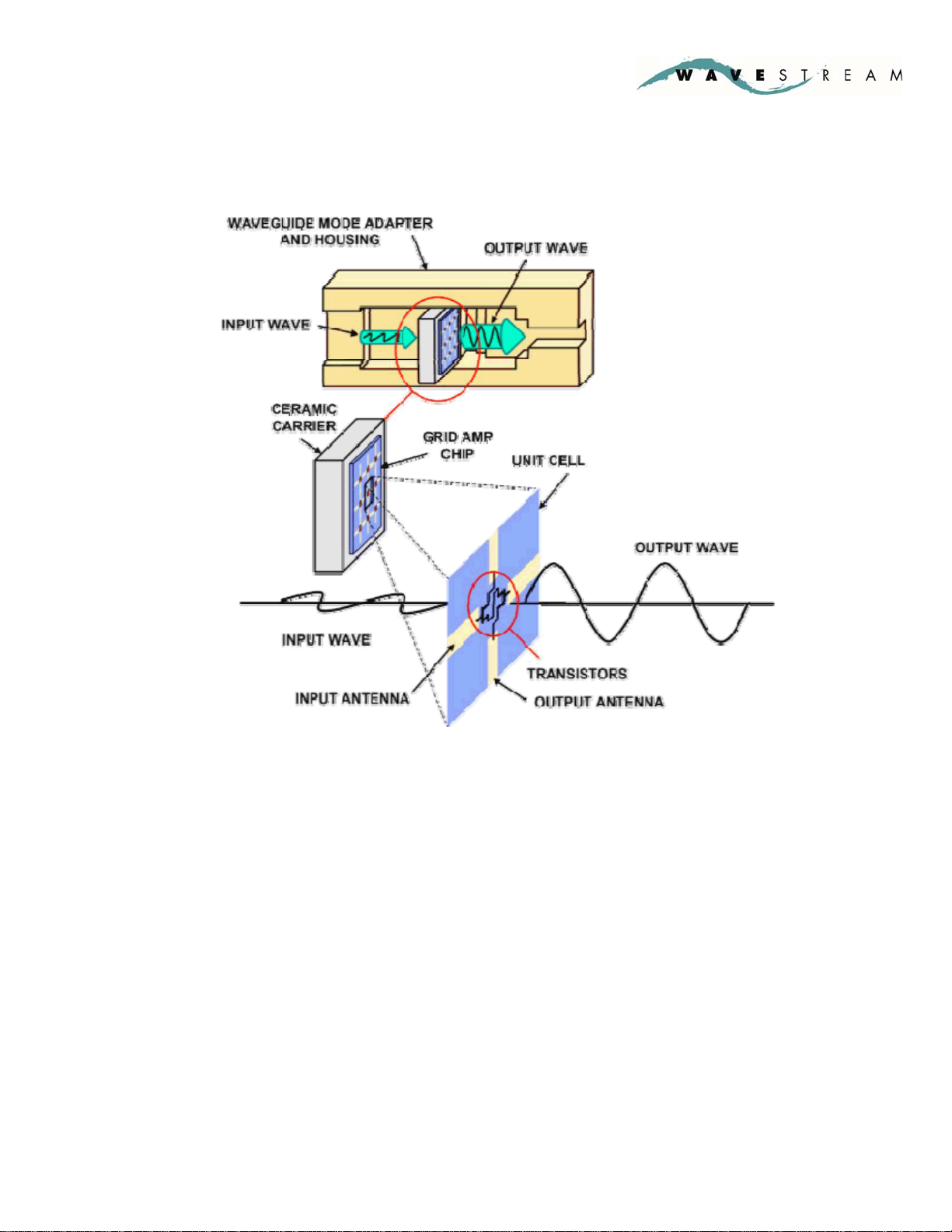
The PowerStream Grid Amplifier is powered by Wavestream’s Grid Amplifier chip
which consists of an array of several hundred transistors which together form an in-
waveguide amplifier as shown in the diagram below:
PowerStream™ Grid Amplifier™ using Patented Spatial Power Combining
Wavestream’s Grid Amplifier architecture provides significant advantages over
traditional SSPAs which use microstrip or waveguide combining. All the MMIC
amplifier outputs are combined in a single stage of combining in air, making the
amplifier highly efficient. Furthermore the signal never traverses a bond wire,
removing a key single point of failure found in traditional amplifiers.

December 2007 Page 14 90-005-0003 Rev X01
50 Watt Ka Feedmount BUC User Manual
INTERFACES
The Unit has the following interfaces:
“IF /REF IN”CONNECTOR (J1)
The “IF / REF IN” Connector is a Type N female connector.
Type N Connector
The Unit requires that the L-Band (1000-2000MHz) Input and a 10MHz
reference are multiplexed into the “IF IN / REF IN” Connector. Most
modems are configured to provide the required multiplexed signal and
reference. This multiplexing can be performed using a bias tee and a
separate reference source if unavailable from the modem.
“RF OUT”CONNECTOR (J2)
The “RF OUT” Connector is a WR28 waveguide flange.
WR28 flange
When operating, the Unit will output up to 50 Watts of RF power at Ka-
Band (30.0-31.0GHz). To make a water-tight connection, the mating
WR28 flange should have an O-Ring groove and the appropriate O-Ring
ought to be inserted prior to mating this interface.
“120VAC IN”CONNECTOR (J3)
The “120VAC IN” Connector is a 3-Pin Circular Connector. This is an ITT
Cannon part with part number CB7-16-10PS. Its mating connector (part
number CB6E16-10SS) has been supplied with the Unit.
ITT Cannon P/N: CB7-16-10PS
The Unit is powered from this connector. At peak output power, the Unit
will not draw more than 6.5 Amps.

December 2007 Page 15 90-005-0003 Rev X01
50 Watt Ka Feedmount BUC User Manual
PRIME POWER INTERFACE PINOUT:
Pin# Signal Name Pin Description
A PRIME PWR +120VAC Line
B PRIME RTN +120VAC Neutral
C GND Ground
MONITOR AND CONTROL INTERFACE (J4)
The “M&C” Connector is a 32-Pin Circular Connector. This is an ITT
Cannon part with part number KPT07A18-32S. Its mating connector
(part number KPT06U18-32P) has been supplied with the Unit.
ITT Cannon P/N: KPT07A18-32S
The Unit uses this connector as a serial RS-485 interface.

December 2007 Page 16 90-005-0003 Rev X01
50 Watt Ka Feedmount BUC User Manual
MONITOR AND CONTROL INTERFACE PINOUT:
Pin # Signal Name Pin Description
Pin A: STDBY_TX*_1 Safety Interlock1 – Unit will not turn on if not
grounded.
Pin B: STDBY_TX*_2 Safety Interlock2 – Unit will not turn on if not
grounded.
Pin C: OVERTEMP High if “Over Temperature” event is occurring
Pin D: OVERRIDE Battle Short (Active High) High = Battle Short
active
Pin E: RESERVED n/a
Pin F: REF_LOCK_DSCRT Reports acquisition of reference signal and
upconverter has locked (active HI)
Pin G: no connect n/a
Pin H: no connect n/a
Pin J: RF_FWD_PWR Analog Output Voltage Proportional to RF
Forward Output Power
Pin K: GND Logic Gnd
Pin L: RS_485-RX+ Serial Communication Channel
Pin M: RS_485-RX- Serial Communication Channel
Pin N: RS_485-TX+ Serial Communication Channel
Pin P: RS_485-TX- Serial Communication Channel
Pin R: RESERVED1 n/a
Pin S: RESERVED2 n/a
Pin T: GND Logic Gnd
Pin U: no connect n/a
Pin V: no connect n/a
Pin W: no connect n/a
Pin X: no connect n/a
Pin Y: no connect n/a
Pin Z: no connect n/a
Pin a: no connect n/a
Pin b: no connect n/a
Pin c: no connect n/a
Pin d: no connect n/a
Pin e: no connect n/a
Pin f: no connect n/a
Pin g: no connect n/a
Pin h: no connect n/a
Pin j: GND Logic Gnd
The default SABUS address of the unit is 0x30(hex).

December 2007 Page 17 90-005-0003 Rev X01
50 Watt Ka Feedmount BUC User Manual
GROUND STUD
Located between connectors J3 and J4 is a ground stud which is screwed
into the main body of the Unit. This should be used to ground the Unit to
the rest of the system.
MOUNTING INTERFACE
•The Unit is designed to mount to a plate via the 2 sets of 3 ¼-20 bolt
holes located on each side of the Unit. The plate should be designed to
be capable of carrying the weight of the Unit. That plate is the typically
attached to a feed arm or other platform. No conductive cooling is
assumed. Therefore, the function of the Unit’s mounting interface is
simply to enable meeting the system vibration and shock requirements.
MOUNTING HOLE PATTERN

December 2007 Page 18 90-005-0003 Rev X01
50 Watt Ka Feedmount BUC User Manual
OUTLINE DRAWINGS
Outline Drawing 1: FRONT VIEW

December 2007 Page 19 90-005-0003 Rev X01
50 Watt Ka Feedmount BUC User Manual
Outline Drawing 2: TOP VIEW
Outline Drawing 3: REAR VIEW
Outline Drawing 4: BOTTOM VIEW

December 2007 Page 20 90-005-0003 Rev X01
50 Watt Ka Feedmount BUC User Manual
ADDITIONAL INFORMATION
The Fans: The Unit cools itself with fans. These fans are weatherized to
handle an extreme environment that includes heavy spray. They will
shut off when the temperature of the Unit is below 10°C. The fans are
the only serviceable part in the Unit. To replace the fan assembly, see
Section 7.
Cable Construction: If the M&C cable is greater than 6 feet, it is
recommended that multi-conductor shielded cable be used to reduce
noise pickup. Shield should be connected to the case. The Ground Stud
on the chassis can be used for this purpose.
This manual suits for next models
1
Table of contents


