WaveWare SPS5 V9 User manual

[1]
SPS5
V
9 SERIES PAGING SYSTEM MANUAL
WAVEWARE TECHNOLOGIES INC. V2.0 OCT 2019
Phone: 1-972-479-1702 Toll Free: 1-800-373-1466 Fax: 1-972-479-1735
E-mail: [email protected] Technical Support: [email protected]
TABLE OF CONTENTS
INTRO TO THE V9 PAGING SYSTEMS........................................................................................... 3
SYSTEM OVERVIEW ................................................................................................................................3
MODELS &FEATURES.............................................................................................................................4
Current Systems ............................................................................................................................4
Legacy Systems .............................................................................................................................4
Features & Capabilities .................................................................................................................4
OBTAINING PAGERS FOR YOUR PAGING SYSTEM...........................................................................................7
FIRST TIME INSTALLATION ......................................................................................................... 9
V9 ENCODER SETUP SOFTWARE GUIDE .....................................................................................10
CONNECT TO THE SYSTEM......................................................................................................................10
THE MAIN MENU ................................................................................................................................12
FUNCTIONS.........................................................................................................................................13
1. Pager Families .........................................................................................................................13
2. Group Paging ..........................................................................................................................14
3. Canned Msgs ...........................................................................................................................14
4. Settings....................................................................................................................................15
5. Test Encoder & Range Test .....................................................................................................18
6. Discover...................................................................................................................................20
WEB CONFIGURATION GUIDE ...................................................................................................20
CONNECTING TO THE SYSTEM.................................................................................................................20
MESSAGING........................................................................................................................................21
PAGER FAMILIES ..................................................................................................................................22
PAGER GROUPS ...................................................................................................................................24

[2]
PREDEFINED MSG. ...............................................................................................................................25
SERIAL PORT .......................................................................................................................................26
NETWORK ..........................................................................................................................................27
RF ....................................................................................................................................................28
STATUS ..............................................................................................................................................29
APPENDIX A – TAP INTERFACE SPECIFICATIONS.........................................................................30
SYSTEM IDENTIFICATION COMMAND........................................................................................................31
PAGING SESSION LOGIN ........................................................................................................................32
PAGING OPERATION .............................................................................................................................32
PAGING SESSION LOGOUT .....................................................................................................................34
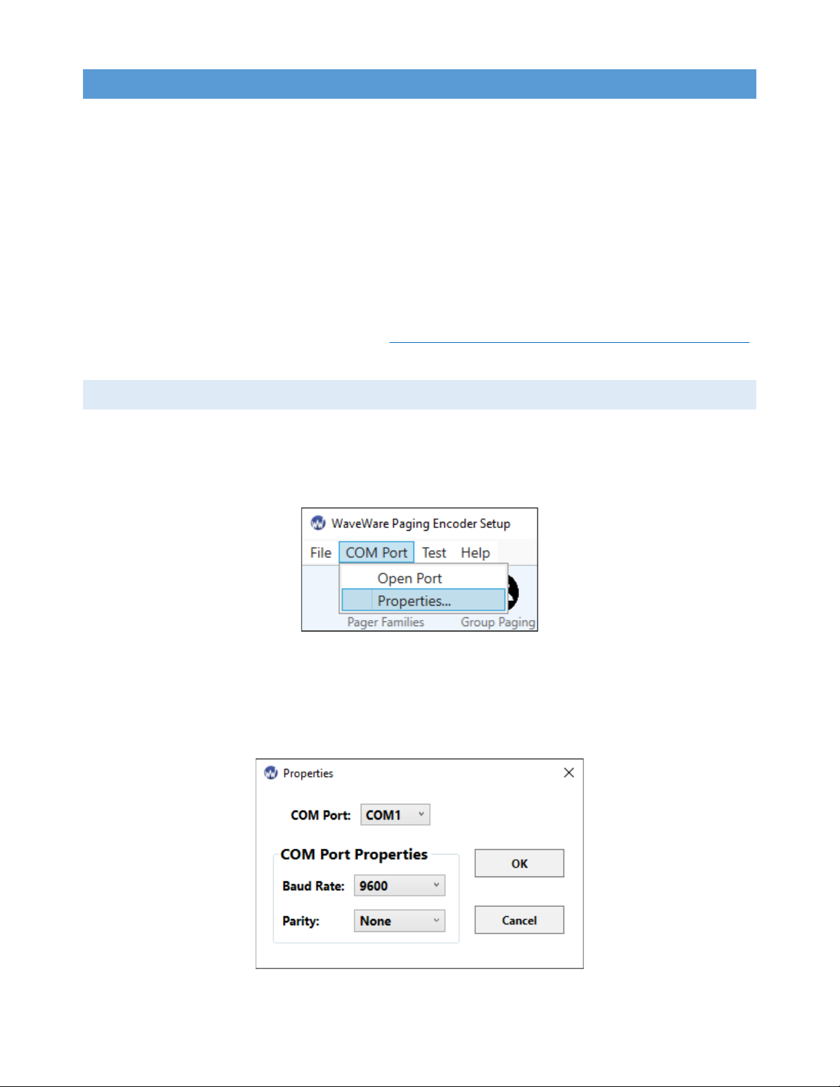
APPENDIX B – COM PORT SETTINGS..........................................................................................35
APPENDIX C – TAP CHECKSUM CALCULATION ...........................................................................36
APPENDIX D – TAP EMBEDDED CONTROL CHARACTERS.............................................................37
APPENDIX E – TAP RESPONSE CODES ........................................................................................38
APPENDIX F – EXTENDED ID PROCESSING..................................................................................38
APPENDIX G – WAVEWARE INTERFACE SPECIFICATIONS ...........................................................40
PAGING MESSAGE FORMAT ...................................................................................................................40
RESPONSE TO ALL COMMANDS...............................................................................................................42
SETUP COMMAND ...............................................................................................................................45
STATUS COMMAND..............................................................................................................................45
APPENDIX H – COMP1 INTERFACE SPECIFICATIONS ...................................................................46
APPENDIX I – COMP2 INTERFACE SPECIFICATIONS ....................................................................47
APPENDIX J – SCOPE INTERFACE SPECIFICATIONS......................................................................49
PAGING MESSAGE COMMAND ...............................................................................................................49
RESPONSE TO ALL COMMANDS...............................................................................................................50
APPENDIX K – TIMED MESSAGING FUNCTION ...........................................................................51
APPENDIX L – SPS5 V9E SYSTEMS’ CONNECTORS AND INDICATORS ...........................................52
APPENDIX M – SITE SURVEY......................................................................................................53
SPS5-V9 SERIES WARRANTY AND OTHER INFORMATION...........................................................54

[3]
INTRO TO THE V9 PAGING SYSTEMS
The SPS5 v9 series of paging systems transmit POCSAG messages and/or tones to Paging Data
Receivers (PDRs). These messages can come in various paging protocols, or in various methods of delivery
such as automatic transmission, manual typing of messages, and it can also receive messages from other
devices as long as the paging data protocol is compatible with an SPS-5v9 system. Below is a picture of our
current line of paging systems which will be broken down as well as any other systems that are compatible
with the Paging Encoder Setup v9 software. Each paging encoder can be sold separately without the radio
transceiver for your own custom build, and the main operation of the encoder does not change.
Figure 1: Current Paging System Lineup
SYSTEM OVERVIEW
Your WaveWare v9 Series Paging System includes a UHF or VHF transceiver, an onboard RS-232 Serial
COM port, and an Ethernet interface for communications and encoding paging messages for RF transmission
using the industry standard POCSAG paging protocol. The v9 series Radio Transceiver maintains an input
buffer, which can receive commands from a Host Device by a Serial or Ethernet connection while a page is
being transmitted. When a command is received from the Host Device, the Encoder responds with a message
back to the Host Device, encodes the paging message into POCSAG format, and transmits the encoded paging
message to your paging receivers.The Paging Control Protocols, defined in this handbook and detailed in
the appendices, allow you or others to develop software or devices to directly control the paging encoder.

[4]
MODELS & FEATURES
CURRENT SYSTEMS
Figure 2: Current Paging System Comparison
Model No.
Serial
Ports
Ethernet
Sockets
Paging Transmission
Wattage
Duty Cycle
Range
Serial
Config.
Web
Config.
SPS5 v9E
1
2
2 or 5 Watts
30% - 70%
Y
Y
SPS5 v9S
1
0
2 or 5 Watts
30% - 70%
Y
N
SPS5 v9E-XL
1
2
5 Watts
100%
Y
Y
SPS v9E-HP
1
2
10 - 25 Watts
80%
Y
Y
LEGACY SYSTEMS
These legacy systems will not be discussed in this manual, but they are able to be used with the
WaveWare V9 Encoder Setup Software v9.3.xx.
Figure 3: Legacy System Comparison
Model No.
Serial
Ports
Ethernet
Sockets
Paging Transmission
Wattage
Recommended
Duty Cycle Range
Serial
Config.
Web
Config.
SPS5 v9
2
0
2 or 5 Watts
30%-70%
Y
N
SPS5 v8
1
0
2 or 5 Watts
30%-70%
Y
N
FEATURES & CAPABILITIES
The capabilities of the SPS5 Series Paging Systems is standard across the board with the exception of
the SPS5 v9S and Legacy Systems: These do not have an Ethernet Port and thus cannot be configured or
receive messages over IP. Below is a comprehensive list of the features and capabilities you can expect
from your WaveWare V9 Series Paging System:
•SERIAL PORT CONTROLLED OPERATION via the RS-232 Serial Port with programmable
communication parameters. Valid serial baud rates are: 300, 1200, 2400, and 9600, with None, Even,
or Odd parities. Default setting is 9600-None, unless specified differently by a customer requirement.
•UHF & VHF BANDS WaveWare has FCC Shared-Use Licenses for different frequencies in the UHF
band (450-470 MHz). For VHF or any UHF frequencies we do not own, we can handle your site’s
application to the FCC for a fee. This only applies to U.S. installations.

[5]
•ETHERNET PORT CONTROLLED OPERATION via the Ethernet port with 2 simultaneous
connections allowed. Since the paging system exists as a device on your network, the usual
modifiable settings such as IP, Port, Gateway, DCHP, etc. are configurable via the Serial Port if you
have trouble connecting it over IP.
•INDEPENDENT CONFIGURATIONS for the Serial port and for each of the Ethernet socket
connections. Each of these configurations can exist and be used simultaneously with each other.
•2 CONFIGURATION METHODS using either the Windows V9 Encoder Setup Software to connect
through the Serial port, or a web browser connecting through the Ethernet port.
•2 TO 25 WATT OPTIONS depending on the model chosen with an option to upgrade to 50 Watts
using a TPL Amplifier Kit.
•INDUSTRY STANDARD POCSAG Paging Protocol Covering the Full Range of Paging Functions,
Including:
o512, 1200 and 2400 bps RD Baud Rates
oAlphanumeric (Text), Numeric and Tone/Vibe Only Paging Message Formats
oMultiple Tone and Vibration Patterns
oBatch Message Delivery up to 32 messages, with 240 Characters per Message (500
Characters in WaveWare Paging Protocol)
•MULTIPLE PAGING PROTOCOLS customizable for each connection. The compatible protocols are:
oTAP v1.8: A bidirectional protocol that has the most robust and secure communications
interface for radio paging.
oPET: which provides human readable messaging prompts and also supports TAP protocol
message formats.
oCOMP1: Delivers a <CR> or <CR><LF> delimited data to one more pagers.
oCOMP2: A command string composed of PagerID<CR>Message<CR>.
oScope:A proprietary single serial command string that Includes Cap Code, Function Code, RF
Data Rate, and message values.

[6]
oWaveWare: A similar protocol to Scope with the exception of having extended messages up
to 500 characters.
oSNPP: A bidirectional protocol originally designed as a paging gateway protocol into wide-
area paging networks via Ethernet.
•EXTENDED PAGER ID METHOD TAP, COMP2, and SNPP compatible extended interface supporting
embedded control characters and paging message encoding parameters appended to the Pager ID
field.
•PAGER ID AS CAP CODE MODE This allows a pager ID value in the COMP2, TAP or SNPP protocols
to be treated as a Cap Code, allowing a bypass of the Pager Database. This method reduces database
configuration efforts and opens the Paging Encoder up to use of the full approximately 2 million
POCSAG Cap Code values.
•CARRIER SIGNAL DETECTION an option that automatically delays your transmission while a nearby
signal with the same frequency is operating.
•CARRIER DETECT POLARITY supports the integration of the WaveWare v9E/v9S Paging Encoder to
a variety of radio transmitters. It can be set at 0 or 5 Volts.
•PROGRAMMABLE PAGER DATABASE Supporting 5,000+ pagers, and up to 10 Groups of 15 Pager
IDs each, Stored in Non-Volatile EEPROM Memory. The Pager Database is “Not Required” for
WaveWare Protocol, Scope Protocol, the Extended Pager ID Method, or Pager ID as Cap Code Mode.
Windows Software, called WaveWare SPS-5 v9 “Paging Encoder Setup” is provided for Pager
Database Programming, Com Port Settings, Ethernet settings, Range Testing, and General Messaging.
•VERBOSE/NON-VERBOSE RESPONSE MODES:Verbose Output means the paging system
responses include more information than Non-Verbose responses.
•TRANSMITTER DUTY CYCLE MANAGEMENT in Percentage, from 0 to 100. A 0 value in this
context means 100% as well.
•DATA ENCODING POLARITY supports the encoding of POCSAG messages for compatibility with
different pager models. Can be set to Normal or Reverse Polarity.
•VARIABLE BATCH MESSAGING SIZE ranging from 1 to 32 messages per batch. Batch Messaging
allows higher message throughput by outputting a single POCSAG preamble for the batch of
messages.

[7]
•TIMED MESSAGING FUNCTION allows a paging system to monitor the host system, and
automatically deliver alert paging messages if the host system does not communicate to the paging
system within a 2 Min. time cycle. The Timer Triggered Messaging Function can also be used as a
repetitive RF ping for Fully Supervised Applications. Predefined alert messages can be up to 60
characters in length.
•FLOW CONTROL SIGNALING accommodates a variety of methods of busy terminal signaling. Valid
Flow Controls include:
oNone
oHardware (CTS)
oSoftware (XOFF/XON)
oAlt Hardware (CTS gets asserted before message response)
oAlt Software (XOFF is outputted before message response)
•DIRECT ENCODER CONTROL (no pager database) is available in the following ways:
oSetting Pager ID as Cap Code and running TAP or COMP2 Paging Protocols.
oUsing Extended Pager ID Encoding and running TAP, COMP2, or SNPP Paging Protocols.
oUse the Scope or WaveWare Paging Protocols.
OBTAINING PAGERS FOR YOUR PAGING SYSTEM
You can use a wide variety of Paging Receiver types with WaveWare v9 Series Paging Systems,
including Alphanumeric, Numeric and Tone/vibe and Wireless Message Centers. WaveWare Compatible
Paging Receivers can be obtained from many sources including WaveWare Technologies. The Paging
Receivers that you obtain for use with WaveWare v9 series paging systems should meet the following basic
specifications:
•FREQUENCY: All paging receivers used with v9 series paging systems must have the same frequency
and must match the frequency of the paging system transmitter.
•POCSAG: All paging receivers must be POCSAG compatible in order to be used with v9 series paging
systems.

[8]
•BAUD RATE: Each paging receiver must have a baud rate of 512, 1200, or 2400 to be used. Different
baud rates can be used in a single installation.
•CAP CODES: Each paging receiver must have at least one active cap code programmed into it.
Figure 4: POCSAG Device Examples
ALPHANUMERIC PAGERS NUMERIC PAGERS
PAGING DATA RECEIVERS PAGING DATA REPEATERS
WALLPAGERS

[9]
FIRST TIME INSTALLATION
Your WaveWare v9 Series Paging System includes: 1 Transmitter Unit, a “Rubber Duck” Antenna, 1
RS-232 Cable, 1 Ethernet Cable (where applicable), Mounting Screws/Plastic Anchor Kit and a Power Supply.
To install the paging system, please follow these steps:
1. ATTACH THE “RUBBER DUCK” ANTENNA to the transmitter output. In normal paging operations,
the paging transmitter antenna should be oriented in a vertical position to maximize the paging
range.
(Note: Don’t attempt to operate the system without the antenna connected to the paging transmitter, as
damage to the paging transmitter may occur.)
2. REMOVE THE FRONT COVER OF THE PAGING SYSTEM AND HOLD IT UP AGAINST THE WALL
or a non-metallic vertical surface to mark where the 2 holes will go where you will mount the paging
system.
3. DRILL AND ATTACH THE TOP # 8 X ¾” SHEET METAL SCREW to the wall or vertical surface (use
the plastic anchors if needed).
4. MOUNT THE SYSTEM ONTO THE TOP SCREW, using the 1-slotted mounting hole near the top of
the unit inside the enclosure. PLACE THE 2ND SCREW into the round hole near the bottom of the
enclosure, TIGHTEN BOTH SCREWS AND RE-ATTACH THE FRONT COVER of the paging system.
5. PLUG THE RS-232 CABLE into an available DB9 Serial male connector on the back of the Host
Device, and connect it to the DB9 female connector on the paging system.
(Note: If the Host Device Serial port has a DB25 or USB connector, you will need the appropriate adapter,
which are available from WaveWare or from a computer supply company.)
6. PLUG THE POWER SUPPLYinto an 110V AC power outlet and the adapter to the paging system.
(Note: The green power LED indicator on the paging system should be ON when power is properly applied.)
7. PROGRAM THE PAGER DATABASE, if needed, with the WaveWare v9 Encoder Setup Software,
which is on our website at: https://www.wirelessmessaging.com/sps5-series-encoder-programming.
Below are 2 guides about setting up a paging system using either Serial or Ethernet connections.

[10]
V9 ENCODER SETUP SOFTWARE GUIDE
When using WaveWare’s Paging Encoder Setup v9, all system communications are sent through a
serial connection. Since most PCs do not have serial ports these days, this is accomplished by using USB
ports via a USB-Serial Adapter.
VERSION REQUIREMENTS:
•A Windows 8/10 PC is required to use version v9.3.xx.
•If you are using a Windows OS older than Windows 8, please download and install version v9.2.11
•Old/New SPS-5 software is available at: wirelessmessaging.com/sps5-series-encoder-programming
CONNECT TO THE SYSTEM
To choose your connection and its settings, navigate to COM PORT > PROPERTIES (fig. 5).
Figure 5: COM Menu
After opening the COM PROPERTIES WINDOW(fig. 6), you will see 3 separate dropdown menus
that contain the settings needed to open a COM connection to your paging encoder.
Figure 6: COM Properties

[11]
•COM PORT – This is a list of the current serial or USB-serial connections on your PC.
•BAUD RATE – This is a list of valid serial port transmission rates.
•PARITY – These are compatible data binary formats sent through the serial connection.
PAGE 14 HAS A STEP-BY-STEP PROCESS OF CONNECTING TO THE CORRECT COM PORT:
1. Make sure your system is on and connected. Navigate to COM PORT >PROPERTIES1.
2. Look at the list and write down or remember each active connection.
3. Exit PROPERTIES and unplug your serial connection to your paging system from the PC end.
4. Open COM PORT >PROPERTIES and check the COM port menu for the missing COM port connection.
5. Exit PROPERTIES again and re-plug your serial connection back into the PC.
6. Open COM PORT >PROPERTIES again and chose the COM port that was missing before.
7. Press the OPEN COM button to detect and connect to the paging system (fig. 7).
8. After acknowledging that your paging system has been detected, press OK to start reading it.
Figure 7: Opening the Port
1If you have only one COM port or know which port is the correct one, select that port and skip steps 2-6

[12]
THE MAIN MENU
Figure 8: Main Menu Options
•OPEN DATABASE FILE – Loads a saved database configuration, replacing the current one.
•NEW DATABASE – Clears the current database configuration.
•PROGRAM ENCODER DATABASE – Programs the current database to the paging encoder.
•READ ENCODER DATABASE – Reads the paging encoder database, replacing the current one.
•SAVE DATABASE – Saves an already defined database configuration.
•SAVE DATABASE AS – Defines the database configuration file and saves it.
•EXPORT AS OMNI DATABASE – Save the current database as an OMNI Messaging Server database.
•PRINT DATABASE CONFIGURATION – Print the current database configuration.
•EXIT – Exits the software. This will automatically close any open port.
•SEND MESSAGES – Opens the TEST ENCODER window.
•PAGING ENCODER SETUP GUIDE – Opens this guide.
•SPS5 V9 SERIES MANUAL – Opens the manual for the SPS5 v9 series of paging systems.
•ABOUT PAGING ENCODER SETUP – Shows the splash screen.

[13]
FUNCTIONS
This section will cover the main functions of the Paging Encoder Setup V9 Software (fig. 9).
Figure 9: Main Functions
1. PAGER FAMILIES
PAGER FAMILIES (fig. 10) displays the current database’s list of valid pager IDs, capcodes, and
messaging formats used for transmitting pages, and each row in the window is a separate Pager Family
entry. Each encoder can have up to 50 different Pager Family entries in a single database configuration.
Figure 10: Pager Family Row
1. ACTIVE – Controls if a Pager Family is checked when paging data is received from a Host Device.
2. PAGER QTY – Sets the range of ID and capcode pairings. It can be set from 1-999.
3. START ID – Sets the first ID used in order to calculate the range. Valid IDs range from 1-9999.
4. END ID – An unmodifiable display of the last calculated ID in the range.
5. START CAPCODE – Sets the first capcode used in order to calculate the range.
6. END CAPCODE – An unmodifiable display of the last calculated capcode in the range.

[14]
7. PAGER TYPE – Changes the message type pagers receive from this Pager Family.
8. FUNCTION CODE – Sets the function code used by a pager when it receives a page from this Pager
Family. Some pagers refer to function codes as letters. In this case: 1=A, 2=B, 3=C, and 4=D.
9. DATA RATE – Sets the transmission rate in this Pager Family. Choices are: 512, 1200, and 2400.
10. PREFIX MSG – Adds a prepended message from CANNED MSGS to pages from this Pager Family.
11. SUFFIX MSG – Adds an appended message from CANNED MSGS to pages from this Pager Family.
2. GROUP PAGING
Figure 11: Group Paging Column
The GROUP PAGING Window (fig. 11) displays the current database’s pager
IDs bound together by a common group ID.
1. REFERENCE – A small tag to identify what the group is for.
2. ACTIVE – Controls if the group is checked when paging data is received from
the Host Device.
3. GROUP ID – The ID that triggers a group page. It must be an ID not used
in any Pager Family.
4. PAGER IDS– A list of up to 15 Pager IDs in the paging group. It must be an
ID in a Pager Family.
5. TIMER ACTIVE - This will send a page every 2 minutes to the pagers listed
in that Group unless the Host Device issues a Reset Command.
6. TIMER MSG # - The message, created in Canned Msgs,that pages to the
associated Paging Group when the timer’s 2 minutes have passed.
3. CANNED MSGS
The CANNED MSGS. WINDOW (fig. 12) is very simple with only text prompts for up to 15 messages
programmed to the encoder for use as a prefix, a suffix, or as a timed message.The messages will save if
the CLOSE button is used instead of the OK button.

[15]
Figure 12: Canned Msgs. Window
4. SETTINGS
SERIAL SETTINGS
Figure 13: Serial Settings Tab

[16]
1. PAGING PROTOCOL – Determines the data format the Encoder is looking for when the Host Device
sends paging data.
2. [NON-]/VERBOSE MSGS. – Controls how paging system replies are sent to a host device.
3. BAUD RATE – Controls the transmission rate the serial port input is looking for from a host device.
4. PARITY – Controls the byte format the input is looking for from a host device.
ETHERNET (IP) SETTINGS
Figure 14: IP Socket Tab Figure 15: IP Network Tab
1. PAGING PROTOCOL –the data format the encoder is looking for when the host device sends pages.
2. [NON-]/VERBOSE MSGS. – Controls how paging system replies are sent to a host device.
3. ASSUME PAGER ID AS CAPCODE – The encoder looks for capcodes instead of translating IDs.
4. IP PORT – The port a paging system looks at when searching for data from a host device.
5. MAC ADDRESS – The address of the Network Interface Card in the paging system.
6. DEVICE NAME – The name that appears in the Discover and Reset Tool and on the network.
7. ETHERNET ACTIVITY RESET OF TIMED PAGING – Controls if a timed group message can be reset.

[17]
8. USE DHCP – Controls if the IP address and network is set automatically or if it is entered manually.
9. IP ADDRESS – The network address of the paging system.
10. SUBNET MASK – Sets how your network is sub-divided.
11. PRIMARY/SECONDARY DNS– Sets the 2 IPs of Domain Name Servers used by your network.
12. DEFAULT GATEWAY– The address connecting the paging system’s LAN to other networks.
ADVANCED SETTINGS
You shouldn’t need Advanced Settings for most installations unless you know what changes you need.
(Password is: maint)
Figure 16: Advanced Settings
1. CARRIER DETECT POLARITY – a transmitter compatibility setting for detecting carrier signals.
2. DATA POLARITY – allows paging messages to be encoded with normal or inverted data decoding.
3. TRANSMITTER DUTY CYCLE – Controls the amount of time the radio is active in a cycle.
4. MESSAGES PER BATCH – Controls how many messages are sent by the transmitter in a single cycle.

[18]
5. CARRIER SIGNAL DETECTION – Controls if the paging system will check for carrier signals.
6. INCREMENT CAPCODES BY 8 – Changes whether the capcodes number sequentially or by 8 for each
ID in PAGER FAMILIES.
7. PAGING SITE LICENSE CALL SIGN – Issued to paging systems so the FCC knows it’s a valid paging site.
8. SERIAL PORT RESET OF TIMED PAGING – Controls if a timed group message can be reset.
9. ASSUME PAGER ID AS CAPCODE – The encoder looks for capcodes instead of translating IDs.
10. DISCARD <LF> CHARS IN COMP1 – Removes all Line Feed characters from any COMP1 message.
11. DISCARD BLANK MSGS IN COMP1 – Prevents empty COMP1 messages from transmitting.
12. FLOW CONTROL – Controls how the encoder interacts with host device requests and messages.
13. RESET TO DEFAULTS – Wipes the current database and resets it to default values.
5. TEST ENCODER & RANGE TEST
Figure 17: Test Encoder Window

[19]
1. PAGER ID/CAPCODE – Enter an ID that’s in PAGER FAMILIES, or a capcode if ID as Capcode is turned
on. If capcodes are used, the first Family sets the Data Rate, Pager Type, and Function Code.
2. FUNCTION CODE – Sets the function code manually. Only used with Scope protocol testing.
3. RF DATA RATE – Sets the data rate manually. Used with Scope and WaveWare protocol testing.
4. SEND – Pushes a single page to the radio transmitter using the parameters set in Test Encoder.
5. PAGER MESSAGE – A textbox where any valid paging message can be written. You can also type out
any messages you want to save.
6. SAVED MESSAGES – A repository of messages saved to disk. Best used for OTA Commands. The ADD,
REPLACE, and DELETE buttons allow users to easily change the repository.
7. COM PORT LOG – Shows easily readable serial responses from the paging system.
8. LOG TO FILE – Toggles whether any Test Encoder or Range Test activity is logged.
The START RANGE TEST button takes you to the RANGE TEST window (fig. 18), which allows you to
repeatedly send messages to a specific pager ID.
Figure 18: Range Test Window
1. BASE MESSAGE – The message you want to send during the range test. The message number is
appended to the end of the base message.
2. PAGER ID/CAPCODE – Enter a valid ID that exists in PAGER FAMILIES, or any capcode if ID as Capcode
is turned on.
3. REPEAT TIMER – Sets the amount of time between pages.
4. START/CANCEL – Starts/Exits RANGE TEST. You can press Start during a range test to update the pager
ID and base message. This causes the message number to reset.

[20]
6. DISCOVER
The DISCOVER WINDOW (fig. 14) is a fairly simple function that allows you to find WaveWare
devices on your network. This is usually your Ethernet connection if you also have a Wifi connection. When
you click the DISCOVER button, a list will populate containing all the IP addresses and types of WaveWare
products on your network (fig. 15).
Figure 14: Discover Window: OFF Figure 15: Discover Window: ON
WEB CONFIGURATION GUIDE
CONNECTING TO THE SYSTEM
(Note: These methods will only work if your network is using DHCP or if the static IP settings have already
been programmed into the system. Otherwise, the IP & Network Settings will have to be set using the
WaveWare Paging Encoder Setup Software before using Web Configuration.)
1. Connect the paging system to the same network as the PC you will use to setup the paging system.
2. There are 3 different ways to open up the web browser configuration page. Each one of these accomplish
the same goal so choose whichever method is best for you.
Other manuals for SPS5 V9
1
This manual suits for next models
6
Table of contents
Other WaveWare Microphone manuals