WaveWare SPS-5 User manual

Paging System Handbook
Version 7.XX Firmware
WaveWare Technologies, Inc. Copyright 2003 All Rights Reserved
WIRELESS COMMUNICATION SYSTEMS

2
Contents
Introduction - 3
Obtaining Pagers for your Paging System - 5
Paging System Operation - 6
Paging System Installation - 7
Trouble Shooting - 8
Appendix A – TAP Interface Specifications - 10
Appendix B – DIP Switch Settings - 14
Appendix C – TAP Checksum Calculation - 15
Appendix D – TAP Response Codes - 16
Appendix E – Extended ID Processing - 17
Appendix F – Embedded Control Characters - 18
Appendix G – WaveWare Interface Specifications - 19
Appendix H – COMP1 Interface Specifications - 26
Appendix I – COMP2 Interface Specifications - 27
Appendix J - Timed Messaging Function - 29
Appendix K - Contact Monitoring Function – 30
Appendix L – Connectors and Indicators - 31
Warranty: WaveWare Technologies, Inc. warrants this equipment to operate properly for a period of one year from
date of shipment from WaveWare Technologies, Inc. offices, including parts and WaveWare factory labor, but not
including shipping. The warranty becomes void if the equipment is physically damaged by external events.
Disclaimer: This equipment has not been designed to operate as a primary means of life/safety communications,
and should only be used as a secondary means of communications. The nature of radio paging is such that alert
messages are not guaranteed to be delivered to pagers, due to a variety of causes, some of which are out of the
control of the equipment manufacturer and the user of the equipment. The WaveWare paging equipment uses a
one-way radio paging protocol called POCSAG, which relies upon proper operating frequency coordination and
licensing, proper external environmental conditions, and proper equipment maintenance, in order to deliver
messages to pagers in a reasonably reliable manner. WaveWare Technologies, Inc. is not liable for damages caused
by failure of delivery of messages from WaveWare equipment to pagers, beyond the normal warranted equipment
repair or replacement during the warranty period.
Note: This equipment has been tested and found to comply with the limits for a Class A digital device, pursuant to
part 15 of the FCC Rules. These limits are designed to provide reasonable protection against harmful interference
when the equipment is operated in a commercial environment. This equipment generates, uses, and can radiate
radio frequency energy and, if not installed and used in accordance with the instruction manual, may cause harmful
interference to radio communications. Operation of this equipment in a residential area is likely to cause harmful
interference in which case the user will be required to correct the interference at his own expense. Changes or
modifications to the equipment not expressly approved by WaveWare Technologies, Inc. could void the user’s
authority to operate the equipment.
Site Licensing: This equipment requires a site license from the FCC in order to be operated. The site licensing can
be obtained through several means, including Shared-Use Site Licensing from WaveWare, FCC Site Licensing
through WaveWare, directly from FCC licensed Frequency Coordination agencies, or from anyone that can help
you fill out the proper FCC forms payment submittal requirements.

3
Introduction
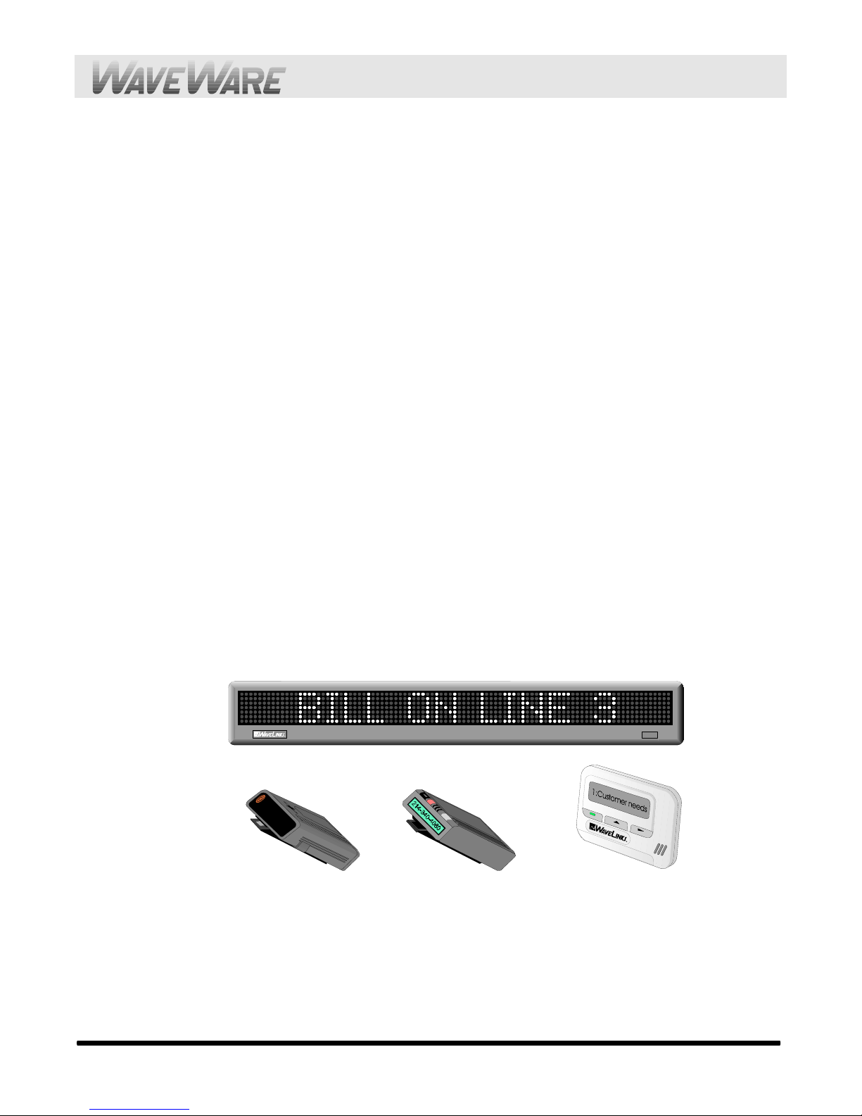
Your WaveWaretm Paging System allows you to send paging messages to one or more persons via pagers, and
devices that incorporate POCSAG paging data receivers. You can setup automatic transmission of messages or you
can compose messages on the fly and transmit them immediately. The WaveWare Paging Encoder can be provided
in either standalone form or bundled with a radio transceiver to become a paging system.
When you attach your paging system to a PC or other Host Device, plug in the provided power adapter, and install
and activate your paging software, you will be ready to make full use of the paging system. The WaveWare
Paging System can have a pager database programmed using the WaveWare Paging Encoder Setup Software, or
you can immediately use the WaveWare Paging System without programming.
Your WaveWare Paging System, using V7.XX firmware, has the following capabilities:
!Serial port controlled operation via RS-232 serial port, with DIP switch configurable communication
parameters. Baud rates of 300, 1200, 2400, and 9600, with None, Even, and Odd parities. Default setting
is 9600 N81, unless specified differently by customer requirements.
!2 Watts effective radiated power with approximately 1 mile range, depending upon terrain and
obstructions. 5 Watt model also available.
!UHF band (450-470 MHz) synthesized frequency transceiver. See the label on the back of the paging
system to identify the operating frequency of the paging system. Default is 467.800 MHz.
!Industry standard POCSAG paging protocol covering the full range of paging functions, including:
Φ512, 1200 and 2400 bps RF data rates, auto-switching
Φtone/vibe only, numeric and alphanumeric paging message formats
Φmultiple tone/vibration patterns
Φbatch message delivery, with up to 240 characters per message (500 characters in WaveWare mode)
!Support for multiple paging control protocols, including:
ΦTAP v1.8 (variations also known as IXO and PET)
ΦExtended TAP (TAP compatible extended interface supporting embedded control characters and
paging message encoding parameters appended to the pager ID)
ΦSimplex TAP, a single serial command string composed of a standard TAP message block. NOTE:
Simplex TAP is the recommended interface protocol for system developers.
ΦCOMP1, delivery of <CR> or <CR><LF> delimited data to one or more pagers
ΦCOMP2, a command string composed of PagerID<CR>Message<CR>
ΦWaveWare, a proprietary single serial command string that includes capcode, function code, RF data
rate, and message values. WaveWare protocol can be used as either simplex or duplex operation.
!Programmable Carrier Detect mode, which allows the automatic delay of transmission while a nearby
transmitter of the same frequency is operating. Default is Carrier Detect On.
!Programmable on-board pager database, supporting approximately 50,000 pagers, and up to 10 groups of
20 pager IDs each, stored in non-volatile EEPROM memory. The pager database is not required for
WaveWare protocol, Extended TAP protocol, or Pager ID as Capcode mode. Windows 32 bit software,
called WaveWare Paging Encoder Setup is provided for pager database programming, range testing, and
general messaging.
!Onboard watchdog timer to keep the paging system on-line at all times
!Hardware or Software Flow Control, DIP switch selectable. Default is Hardware Flow Control.
!Verbose or Non-Verbose Modes, DIP switch selectable. Default is Verbose TAP. Verbose output means
the paging system responses include more information than non-verbose responses.
!Programmable transmitter duty cycle management, in percentage, from 0 to 100. Default is 50% Duty
Cycle. A 0 value also means 100%.

4
!Remote administration of Pager Database. Pager database can be modified using specially formatted TAP
paging messages.
!Programmable Timed Messaging function, allowing the paging system to monitor the host system, and
automatically deliver alert paging messages if the host system does not communicate to the paging system
within a one minute time cycle. The Timer Triggered Messaging function can be enabled or disabled via
programming, and can be used as a repetitive RF ping for fully supervised applications. Predefined alert
messages can be up to 60 characters in length.
!Programmable Alarm Monitoring function, causing delivery of alert paging messages upon a Contact
Close or Contact Open event, or both events. Contact monitoring input is a wet voltage input, ranging
from 5 to 24V, wired into an RJ-45 jack on the paging system. Predefined alert messages can be up to 60
characters in length.
!Programmable maximum batch size for batch messaging, ranging from 1 to 32 messages per batch. Batch
messaging allows higher message throughput by outputting a single POCSAG preamble for the batch of
messages. Default maximum batch size is 10 messages per batch.
!Programmable Pager ID as Capcode mode. This mode allows a pager ID value in the COMP2 or TAP
protocols to be treated as a capcode, allowing a bypass of the pager database, and allowing direct encoding
of the pager ID value as the pager capcode. This method reduces database configuration efforts and opens
the paging encoder up to use of the full approximately 2 million POCSAG capcode values. NOTE: When
Pager ID as Capcode mode is active, all paging messages are output at 512 bps RF data rate.
!Programmable Carrier Detect Polarity, supports integration of the WaveWare paging encoder to a variety
of radio transmitters.
!Programmable Data Encoding Polarity, supports use of Normal or Inverted polarity on the encoding of
messages.
!Programmable busy terminal flow control signaling, using either serial port response code flow control or
CTS/XOFF (hardware/software) flow control. The default is serial port response code flow control. If
serial port response code flow control mode is disabled, DIP 1 of the DIP switch bank toggles between
hardware and software flow control.

5
Obtaining Pagers for Your Paging System
You can use a wide variety of paging receiver types with WaveWare Paging Systems, including tone/vibe,
numeric, alphanumeric, and wireless message centers.
You can obtain WaveWare compatible paging receivers from many sources, including Motorola, NEC, Panasonic,
and others. The paging receivers that you obtain for use with the WaveWare Paging Systems should meet the
following basic specifications:
!Frequency - All paging receivers used with the WaveWare Paging System must be of the same
frequency and must match the frequency of the paging system transmitter. See the label on the WaveWare
Transmitter Unit to identify the operating frequency of your paging system.
!POCSAG - All paging receivers used with the WaveWare Paging System must be POCSAG compatible.
POCSAG is the paging protocol most frequently used in the paging industry.
!Pager Type - You can mix different paging receiver types in a WaveWare installation. You can obtain the
following paging receiver types for use with the WaveWare Paging System:
ΦTone/vibe only, with or without multiple tone/vibrate cadence features. WaveWare Paging Systems
support pagers with multiple tone/vibrate features. WaveWare Tone/Vibe Pagers have two capcodes
and have multiple tone/vibrate features.
ΦNumeric
ΦAlphanumeric
ΦWaveWare Wireless Message Centers (allow group message notification on scrolling multicolor LED
displays, using WaveWare Paging Systems to communicate to the message centers)
!Paging Data Rate - You can mix different paging data rates (baud rates) in a WaveWare installation. The
data rate of the paging receivers can be your choice of 512, 1200, or 2400 bps (bits per second).
!Capcodes - Each paging receiver used in a WaveWare Paging System installation must have one or more
capcodes (addresses) programmed into it. Each paging receiver used with a particular WaveWare
installation, regardless of paging receiver type, must have a unique capcode programmed into it, in order to
be able to transmit messages to that individual paging receiver. Contact your paging systems dealer for
capcode assignment information.

6
Paging System Operation
Your WaveWare Paging System includes a UHF transceiver, and onboard RS-232 communications, that transmits
paging messages using the industry standard POCSAG paging protocol. The RS-232 communications allow you to
interface the paging system to a PC or to other devices and systems that use RS-232 serial communications (Host
Devices). Other models of WaveWare Paging System products include encoder only models, and the combination
of the paging encoder with VHF and UHF radio transceivers.
The types of paging receivers that are compatible with your WaveWare Paging System include:
!Any POCSAG compatible paging receiver operating on the same frequency as the paging transmitter (in
the UHF band) and operating at 512, 1200, or 2400 bps data rate. Pagers of this type include tone/vibe,
numeric, and alphanumeric models.
!WaveWare Wireless Message Centers, operating at the same frequency as your paging system. WaveWare
Wireless Message Centers are normally configured to receive at a 512 bps data rate.
The paging system may be controlled by a PC, or other control system, that is running software designed to
interface to the paging system. WaveWare wireless communication systems software is designed to take full
advantage of the features of your WaveWare Paging System. The TAP, WaveWare, COMP1, and COMP2
interface protocols are defined in this handbook to allow you or others to develop software or devices to directly
control the transmitter.
The paging system maintains an input buffer, which can continuously receive commands from the Host Device
while paging messages are being transmitted. When a command is received from the Host Device, the paging
system responds with a message back to the Host Device. The paging system encodes the paging messages into
POCSAG paging format and transmits the encoded paging message to the paging receivers of your choice.
PC software developed to utilize the WaveWare Paging System can be designed to maintain a simple database of
pager ID numbers, or the software can be designed to allow definition of paging receiver attributes, including:
Pager Type
ΦTone/Vibe Only, with or without multiple tone/vibrate cadences
ΦNumeric
ΦAlphanumeric
Capcode - The unique address assigned to each paging receiver
RF Data Rate
Φ512 bps
Φ1200 bps
Φ2400 bps
Function Code – One of four values that pagers can use to change how the behave when receiving a new
message
The Transmitter Unit may require the setting of an onboard DIP switch to change communication interface
parameters. Refer to Appendix B – DIP Switch Settings for details on how to configure the DIP switches, as
required.
If you want to use the TAP interface protocol with 1 to 4 digit pager IDs, you will need to configure a pager
database, using the WaveWare Paging Encoder Setup software. You can obtain the WaveWare Paging Encoder
Setup software either from the WaveWare Product Support CD or from the WaveWare web site, at:
http://www.wirelessmessaging.com/media/encodersetupv7/WWEncoderSetupV7.exe

7
Paging System Installation
Your WaveWare Paging System includes an encoder/transmitter unit, a “Rubber Duck” Antenna, a serial interface
cable, and an AC/DC power adapter. Refer to the diagram on the following page. To install the paging system,
perform the following steps:
1. Attach the “Rubber Duck” Antenna to the Transmitter Unit. In normal paging operations, the paging
transmitter antenna should be oriented in a vertical position to maximize the paging range.
Note: Do not attempt to operate the paging system without the antenna connected to the paging transmitter, as
damage to the paging transmitter may occur.
2. Mount the Transmitter Unit as required to a wall surface, using the mounting slots. You need to remove
the front cover to install the anchor screw..
3. Plug the AC/DC power adapter into the power connector, and connect the DB9 serial cable between the
paging system and the serial port connector on the back of a Host Device, such as a PC or an alphanumeric
paging terminal. If the serial port has a DB25 connector, you must provide a DB25 to DB9 adapter, which
is available from computer supply companies. Tighten connector screws. Please note that you may require
a null modem adapter and/or other wiring modifications to properly connect to host systems.
4. Plug the AC/DC Power Adapter into a 110 VAC power outlet. The red colored PWR/BAT LED indicator
on the Transmitter Unit should be illuminated when power is properly applied.
5. Program the pager database, if required, using WaveWare Paging Encoder Setup software, which is
available from the WaveWare web site or from the WaveWare Product Support CD
6. If you are using a PC as a Host Device, load paging control software, such as WaveWare software, on the
PC and configure it to operate with your WaveWare Paging System. Make sure the proper serial port
settings are defined. The green colored TX LED indicator on the Transmitter Unit should illuminate
during a paging transmission. If the Carrier Detect function is enabled, you may see the green colored CD
LED indicator temporarily illuminate prior to some paging transmissions, if a carrier signal is detected
from a nearby transmitter at the same frequency as your WaveWare Paging System.

8
Trouble Shooting
POWER
When the WaveWare Paging Transmitter Unit is assembled and power is applied, you should be able to see
a red Power indicator illuminated on the side of the Transmitter Unit. If not, verify that all connections are
tight and verify that 110 VAC power is available at the power outlet. If connections are tight, power is
available and the red Power indicator doesn’t illuminate, determine if the Power Adapter is at fault by
trying another Power Adapter. If the Transmitter Unit still does not respond, the Transmitter Unit is most
likely in need of repair or replacement.
At power-up, the Transmitter Unit is supposed to send a status message through the serial port to the host
PC.
PAGERS
When you send a paging message command to the Transmitter unit from the PC, the green RF TX
indicator on the Transmitter Unit should illuminate for a few seconds to indicate that transmission is
occurring. If you don’t receive a message on the selected paging receiver, follow the checklist below to
troubleshoot paging reception:
1. Pager turned on
2. Pager has fresh battery
3. Pager properly defined in the paging control application software on the host PC.
4. Pager located at least arms length away from Transmitter Unit during transmission. (Some paging
receivers do not properly decode paging messages when the paging receivers are located in close
proximity to the transmitter antenna. Holding a paging receiver at arms length away from a transmitter
antenna is usually sufficient to allow the paging receiver to properly decode a paging transmission).
5. Antenna attached to Transmitter Unit
6. Pager at the same frequency as the Paging System
7. Pager uses POCSAG paging protocol
CARRIER DETECT
The Carrier Detection signal is indicated by the green RF CD indicator on the side of the Transmitter Unit.
When a carrier signal is detected, and the Carrier Detect mode of operation is enabled, the paging system
will delay transmission until the detected carrier signal disappears. If the Carrier Detect operating mode is
enabled in the paging system, and you find that paging transmissions are delayed for significant periods of
time due to interference on the channel, you should temporarily inactivate the Carrier Detect mode to allow
transmissions to occur regardless of other transmissions on the channel. You may find that you get
excellent paging reception even with Carrier Detect inactivated. You may want to contact your nearest
FCC field office to find out what is causing the unwanted interference on your channel. Please note that
the typical WaveWare Paging System installation uses a 2 watt system that operates subservient to other
operators on the same frequency. If you find that the unwanted transmissions are legal, and if you find that
your paging reception is suffering due to the unwanted transmissions from another source, you may have to
change your paging system to another operating frequency. A frequency change is a costly process and
should be avoided.
If you have multiple WaveWare Paging Systems installed in the same facility, and at the same operating
frequency, you should activate the Carrier Detect mode on all paging systems in order to ensure paging
messages are being properly transmitted to paging receivers.

9
SITE SURVEY
Some installation sites might cause paging reception problems. It might be beneficial to perform a site
survey by monitoring the radio waves in the area that you want to install a system. It also might be
beneficial to perform a range test to find out of the installed signal will be strong enough to be received in
all of the areas you want to cover. A site survey consists of both monitoring for radio signals on your
channel, and verifying that the paging system has adequate power to cover the expected area.
Following are some rules of thumb to use in deciding whether or not to perform a site survey.
Perform a site survey if the facility or paging conditions meet one or more of the following criteria:
1. Hospital or medical facility
2. Unobstructed line of sight distance exceeding 1 1/2 miles
3. Building above 5 stories
4. Building greater than 50,000 square ft
5. Multi-building facility
6. Vicinity of seaports and shipyards
7. Pager reception problems occur
8. Excessive carrier signal detection conditions occur at the paging system
You can monitor for radio signals using a simple multi-channel UHF band scanner, from sources like
Radio Shack. You listen to the scanner for any audio output on that channel. The louder the audio, the
stronger the signal.
If the scanning results in excessive use of that radio channel, consider changing the paging system to
operate on another radio channel. Use the scanner to identify the lowest traffic channels of those channels
available to you. You may need to monitor for several minutes to determine which channels are busier
than others.
If pager reception problems occur, and there is not excessive foreign traffic on that channel, then consider
boosting the strength of the paging signal. Typically, when you boost a signal, you will need to change the
paging system equipment and pagers to a channel that allows higher power transmissions, measured in
watts.

Appendix A – TAP Interface Specifications - 10
Appendix A – TAP Interface Specifications
This appendix is included for those who want to develop their own paging control software or add an interface for
the WaveWare Paging System to their existing software applications..
A simple definition of the TAP protocol is that the TAP protocol normally requires a connect and disconnect
process and normally assumes that the Host system maintains a database of pager reference numbers called IDs, and
that the paging system maintains a database of all paging parameters associated with each ID. The TAP interface
supports paging messages up to 244 characters in length. The actual maximum length of transmitted messages in
the WaveWare TAP interface is 245 minus the ID field length. With an ID value of 5, you can transmit up to 245
characters per message. With an ID value of 1233425120, you can transmit up to 235 characters per message.
To configure your WaveWare Paging System to use the TAP paging protocol, you may be required to configure
the DIP switch bank in the paging encoder. Please refer to Appendix B – DIP Switch Settings, for details on
configuring communication protocols. As a quick reference, a typical DIP switch setting for the TAP interface is all
8 switches in the ON position, which tells the system to operate in TAP interface mode, with communication
parameters of 9600N81, hardware flow control, and verbose responses from the encoder.
Your WaveWare Paging System typically communicates with a PC or other host device via RS-232 at 9600 Baud,
8 data bits and 1 stop bit. The eighth data bit is ignored (no parity). You can configure the paging system for other
serial communication parameters. Please refer to Appendix B – DIP Switch Settings, for details on serial
communication parameters.
The paging encoder maintains an input buffer which can receive commands from the PC while a page is being
transmitted. The input buffer should be able to contain approximately ten paging messages before getting full.
When a command is received from the PC, the paging system responds with a message that includes error messages
if the command was not understood or not properly transmitted. The first three digits of each paging system
response conforms to the response codes defined in the TAP v1.8 specification. See Appendix D – TAP Response
Codes for a listing of the response codes.
The paging encoder encodes paging messages into POCSAG paging format and transmits the encoded paging
message. If the Carrier Detect function is enabled, transmissions will be delayed while interfering signals are
detected.
Control characters recognized by the paging system in TAP protocol mode include:
CARRIAGE RETURN <CR> $0D
START OF TEXT <STX> $02
END OF TEXT <ETX> $03
END OF TRANSMISSION <EOT> $04
SUBSTITUTE <SUB>$1A
ESCAPE <ESC> $1B
Control characters generated by the WaveWare Paging System in TAP protocol mode include:
LINE FEED <LF> $0A
CARRIAGE RETURN <CR> $0D
ACKNOWLEDGE <ACK> $06
NEGATIVE ACKNOWLEDGE <NAK> $15
ABANDON TRANSACTION <RS> $1E
ESCAPE <ESC> $1B
END OF TRANSMISSION <EOT> $04
XON <XON> $13
XOFF <XOFF> $11

Appendix A – TAP Interface Specifications - 11
The TAP mode of operation can be supplemented with two additional functions, including Host Monitoring
Function, and Contact Monitoring Function. See Appendix J - Host Monitoring Function and Appendix K -
Contact Monitoring Function, for operational details.
The operational modes available for paging using the TAP Paging Protocol include:
System Identification Command
Paging Session Login
Paging Operation
Paging Session Logout
SYSTEM IDENTIFICATION COMMAND
The System Identification command allows installation programs and other software applications to poll
serial ports for the existence of a WaveWare paging encoder using the standard ATI command. This can
be used for a supervised process (also called keep-alive) where the host system periodically polls the
paging system for a response. When the WaveWare paging transmitter recognizes a command formatted
as ATI<CR>, the transmitter responds with the following message:
WaveWare Paging Encoder v7.28<CR>
The firmware version number is subject to change.
PAGING SESSION LOGIN
The Paging Session Login mode allows a Host Device, sometimes called a Remote Entry Device, to initiate
communications with the paging system. With the WaveWare Paging System, the Login process is
optional. The WaveWare Paging System will automatically login a Host Device and process the paging
message if it recognizes a properly formatted TAP message block at any point in it’s operation.
The Host Device initiates the Login process by transmitting a carriage return <CR> character every two
seconds until the paging system properly responds or until the Host Device times out and notifies the
operator of a bad connection. The paging system will respond with “ID=<CR>” (Note: the quotation
characters are used here only for reference and are not included in the transactions). The “ID=<CR>” will
not be repeated or timed out by the paging system.
The Host Device should respond to the paging system with:
<ESC>PG1<CR> or <ESC>pg1<CR>
The WaveWare Paging System will then respond with:
110 1.8<CR>WaveWare Paging Encoder v7.29<CR><ACK><CR>
The “110 1.8” message indicates that the system conforms to TAP specification version 1.8 and should be
backward compatible with earlier TAP implementations. The paging system then notifies the Host Device
that it is ready to accept messages as follows:
<ESC>[p<CR>
This completes the Login process.

Appendix A – TAP Interface Specifications - 12
PAGING OPERATION
Paging transactions are transmitted in blocks of characters, where one transaction is sent per block. Each
block sent by the Host Device is acknowledged by the paging system. The Host Device must wait for this
acknowledgement before sending the next block. The WaveWare Paging System provides
acknowledgement in the form of an <ACK> character.
The WaveWare Paging System supports TAP message blocks up to 253 characters in length, with a 235
to 244 character message, from 1 to 10 characters for ID (pager number), plus 5 control characters, and a 3
character checksum. (Message field length is restricted as follows: when a 1 character ID is used, a 244
character message can be accommodated, and so on, for a total of 253 characters, such that when a 4
character ID is used, a 241 character message can be accommodated. The maximum ID field length of 10
causes a maximum message field length of 235 characters). A block always carries two fields with their
associated carriage returns. The message field may be empty, but it’s carriage return must be included in
the data block. The TAP message block format is as follows:
<STX>ID<CR>Message<CR><ETX>Checksum<CR>
The ID field is a one to ten character pager number. Leading zeroes are not required. The Message field
accommodates up to 235 alphanumeric characters. The Checksum field provides a checksum for the
previous portion of the TAP message block. See Appendix D – TAP Checksum Calculation, for sample
code to create the checksum field.
The Message field can be formatted as follows:
For alphanumeric paging messages, all 7-bit ASCII “non-control” characters are valid except ^, ~, and
_ (underscore)
For numeric paging messages, valid characters are the numbers 0 through 9, - (hyphen), and space
Control characters can be embedded into paging messages so that high end alpha pagers and paging
data receivers can respond with formatted screen displays and with formatted serial output, as
required. Control characters (typically <CR> and <LF>) can be embedded in messages by using the
Transparency Option. The Transparency Option replaces a non-printable control character with the
SUB (Hex 1A) character immediately followed by the control code offset by 40 Hex. See Appendix G
- Embedded Control Characters for details on how to embed control characters in paging messages.
The WaveWare TAP interface supports ID field lengths from 1 to 10 digits. The ID field can be formatted
using two different methods, as follows:
Method 1 - ID field lengths from 1 to 4 digits will cause a pager database lookup. ID fields of this
format must contain numeric digits only. The numeric ID value will be compared to the ID values
stored in the WaveWare Paging System’s onboard pager database.
Method 2 - ID field lengths from 5 to 10 digits will cause Extended ID processing. Extended ID
processing assumes that the last 3 digits of the ID field define paging message encoding attributes,
while the preceding digits define the pager capcode. Extended ID processing allows you to avoid the
process of configuring a pager database in the WaveWare Paging System. See Appendix E –
Extended ID Processing for details on how to format the ID field.
When the Host Device delivers a TAP Message Block to the WaveWare Paging System, if the message
block is properly formatted, and a 1 to 4 digit ID field matches the pager database, the paging system will
respond with an initial response code as follows:
211 Page(s) Sent Successfully<CR>

Appendix A – TAP Interface Specifications - 13
If your WaveWare Paging System is configured to operate using TAP Non-Verbose mode, the paging
system will respond only with an initial response code of:
211<CR>
Following the first part of the TAP message block response, if the input buffer of the paging system has
capacity for another TAP message block, the paging system will send the following message.
<ACK><CR>
The <ACK><CR> response can be used as a flow control method to prevent overflow and lost messages.
As alternative flow control methods, you can use either hardware or software flow control. If the paging
system DIP switch is set to hardware flow control mode, the RS-232 CTS signal will be deasserted when
the input buffer doesn’t have capacity for another TAP message block, and reasserted when capacity exists
in the input buffer. If the DIP switch is set to software flow control mode, an XOFF character (0x11) will
be output in the response string to indicate the the input buffer doesn't have capacity for another TAP
message block. When capacity is available, an XON character (0x13) will be output.
When the Host Device delivers a TAP Message Block and a checksum error occurs, the paging system will
respond with an error message and a <NAK><CR>, which tells the Host Device to resend the transaction.
See Appendix E – TAP Response Codes for more information on paging system response messages. If the
TAP Message Block checksum is OK, but the Message Block violates formatting rules, the paging system
will respond with an error message and an <RS><CR>, which tells the Host Device to abandon the
transaction. An example error message sequence follows:
514 Checksum Error – Exp. 2:9 Got 2:X<CR>
<NAK><CR>
PAGING SESSION LOGOUT
The Paging Session Logout mode allows a Host Device, sometimes called a Remote Entry Device, to stop
communications with the paging system. With the WaveWare Paging System, the Logout process is
optional. The WaveWare Paging System will automatically login a Host Device and process the paging
message if it recognizes a properly formatted TAP message block at any point in it’s operation.
To initiate a logout (disconnect sequence) the Host Device should send the following to the paging system:
<EOT><CR>
Upon recognizing a logout command, the paging system will respond with:
PAGING EXCHANGE DISCONNECT<CR><ESC><EOT><CR>

Appendix B – DIP Switch Settings - 14
Appendix B – DIP Switch Settings
You may be required to configure the DIP switch bank in the paging encoder to establish the appropriate operating
mode and serial communication parameters.
Your WaveWare Paging System typically communicates with a PC or other host system via RS-232 at 9600 Baud,
8 data bits and 1 stop bit. You can configure the paging system for other serial communication parameters.
The available operating modes include TAP Verbose, TAP Non-Verbose, COMP1, WaveWare, COMP2 Verbose,
and COMP2 Non-Verbose.
COMP2 means that data formatted as PagerID/GroupID<CR>Message<CR> will cause the Message to be delivered
to the specified PagerID or GroupID. TAP and COMP2 Verbose means that the paging system will include human
readable messages after each paging request is received. TAP Non-Verbose reduces the paging system human
readable response to 3 digit numeric codes. In the COMP2 Non-Verbose mode the response is reduced to none at
all. The Non-Verbose modes are useful in situations where you want to minimize the serial data throughput
requirements, which tend to allow paging messages to be delivered more quickly. Refer to Appendix A for a
definition of the TAP protocol and Appendix I for a definition of the COMP2 Verbose and Non-Verbose protocol.
COMP1 means that any data received on the serial port will be sent to all pagers in group one stored in the pager
database. Refer to Appendix H for a definition of the COMP1 protocol.
Independent of operating modes, you can configure the serial port baud and parity, and you can configure whether
hardware or software flow control is used.
DIP Switch Settings
* NOTE: Hardware and software flow control signals are operational only when the “Flow Control Before Serial Response”
option is enabled in the Advanced Encoder Setup section of the encoder setup software.

Appendix C – TAP Checksum Calculation - 15
Appendix C – TAP Checksum Calculation
Following is sample Visual Basic™ code that creates a string to be sent to the paging system. A subset of the string
has a checksum calculation performed on it, and then the checksum and a control character are appended to form the
string to be sent to the paging system. Refer to the TAP specification at http://www.pcia.com, for more details on
the checksum calculation.
'String that checksum is calculated on, of the form:
‘<STX>ID<CR>Message<CR><ETX>
TXString$ = Chr(2) & txtID.Text & Chr(13) & txtMessage.Text & Chr(13) & Chr(3)
'Calculate and append checksum
j = 1
Sum = 0
Do Until j > Len(TXString$)
B$ = Mid(TXString$, j, 1)
D = Asc(B$)
Sum = Sum + D
j = j + 1
Loop
'Create the three characters to be transmitted to represent this checksum.
d3 = 48 + Sum - Int(Sum / 16) * 16
Sum = Int(Sum / 16)
d2 = 48 + Sum - Int(Sum / 16) * 16
Sum = Int(Sum / 16)
d1 = 48 + Sum - Int(Sum / 16) * 16
Check1$ = Chr$(d1)
Check2$ = Chr$(d2)
Check3$ = Chr$(d3)
CheckSum$ = Check1$ & Check2$ & Check3$
'Create complete string to be sent to paging system, of the form:
‘<STX>ID<CR>Message<CR><ETX>Checksum<CR>
TXString$ = TXString$ & CheckSum$ & Chr(13)

Appendix D – TAP Response Codes - 16
Appendix D – TAP Response Codes
Following is a table of response codes supported by the WaveWare Paging System. Please note that a <NAK>
response typically means the message should be resent by the host, and an <RS> response typically means the
message should be abandoned by the host.
Response Code Definition
110 1.8 Paging system supports TAP Specification
v1.8
211 Page(s) Sent Successfully Paging message(s) successfully delivered.
This message is accompanied by an <ACK>
510 Invalid character in pager ID Pager ID field contains illegal characters.
This message is accompanied by an <RS>
511 Invalid pager ID - not in database Pager ID was legal and 1 to 4 characters in
length, but didn’t match database lookup.
This message is accompanied by an <RS>
512 Temporarily cannot deliver. Queue full.
Try later Paging System input buffer is full. This
message is accompanied by an <RS>
514 Checksum Error. Exp XXX; Got: YYY Checksum didn’t match message block. This
message is accompanied by a <NAK>
Note: <ACK>, <NAK>, and <RS> are only representations of the lower order ASCII control characters output by the paging
system. <ACK> represents Hex 06, <NAK> represents Hex 15, and <RS> represents Hex 1E.

Appendix F – Embedded Control Characters - 17
Appendix E – Extended ID Processing
The WaveWare TAP interface and both COMP2 interfaces support ID field lengths from 1 to 10 digits. The ID
field can be formatted as follows:
Standard Method - ID field lengths from 1 to 4 digits will cause a pager database lookup. ID fields of
this format must contain numeric digits only. The numeric ID value will be compared to the ID values
stored in the WaveWare Paging System’s onboard pager database.
Extended ID Method - ID field lengths from 5 to 10 digits will cause Extended ID processing.
Extended ID processing assumes that the last 3 digits of the ID field define paging message encoding
attributes, while the preceding digits define the pager capcode. Extended ID processing allows you to
avoid the process of configuring a pager database in the WaveWare Paging System
Extended ID fields should be of the form:
CCCCCCCERF, where Crepresents the capcode, Erepresents Message Encoding Type, Rrepresents RF data
rate, and Frepresents Function Code.
The Extended ID field can be represented in either numeric or alphanumeric format. All Extended ID fields must be
between 5 and 10 digits in length to cause the paging system to perform Extended ID processing. Incorrect
formatting of extended ID fields causes a <NAK> response combined with an explanation message.
CCCCCCC is a 2 to 7 digit numeric value representing a pager capcode. Leading zeroes are optional except in the
case of capcodes 8 and 9, which should be represented with at least one leading zero, e.g. 08 or 09.
Eis the message encoding type, where “0” (zero), “n”, or “N” represent “numeric encoding”, and “1”, “a”, or “A”
represent “alphanumeric encoding”. The numeric values for Eare provided to support numeric-only ID fields in
paging control software.
Ris the RF data rate, where “5” represents 512 bps, “1” represents 1200 bps, and “2” represents 2400 bps.
Fdefines the function code to be delivered, where “1” is function code 1, “2” is function code 2, “3” is function
code 3, and “4” is function code 4. A function code of “0” is also valid. A function code of “0” causes the default
function code for a particular Message Encoding Type (“E”) to be substituted. The default value for Fis “4” when
the Evalue is “alphanumeric encoding”, and “1” when the Evalue is “numeric encoding”.
Following are valid example Extended ID fields causing Extended ID processing:
08A20 – Causes delivery of a standard (function code 4) alphanumeric message to capcode 0000008 at 2400 bps
08A24 – Same result as above
0008124 – Same result as above
0000008124 – Same result as above
11A53 – Causes delivery of an alphanumeric message with function code 3 to capcode 0000011 at 512 bps
0000011A53 – Same result as above
11N53 – Same result as above, but with numeric encoding
038N52 – Causes delivery of a numeric message with function code 2 to capcode 0000038 at 512 bps

Appendix F – Embedded Control Characters - 18
Appendix F – Embedded Control Characters
When using WaveWare mode it is not necessary to make use of the <SUB>control character. Since WaveWare
mode does not use the <CR> control character it is only necessary to hit carriage return on your keyboard to have it
show up on the pager display.
To embed a control character in a TAP mode paging message however, it is necessary include a <SUB>control
character followed by an offset version of the control character you want to embed. You offset the control character
by adding 40 HEX to the control character, to make the character printable. Adding 40 HEX to Carriage Return
gives you M. Adding 40 HEX to Line Feed gives you J. The character combination of <SUB>M causes a Carriage
Return control character to be embedded in the encoded paging message, while <SUB>J causes a Line Feed control
character to be embedded. The <SUB> character needs to be passed to the WaveWare Paging System as a HEX
character.
In the WaveWare Paging Encoder Setup software, you can embed a Carriage Return by entering <CR>in the
message body, and embed a Line Feed character by entering <LF>in the message body. The use of the <SUB>
character will be done by the software.
In the Microsoft Visual Basic programming language, you can use the following code example to define the
embedded control character string to be delivered through the serial port to the paging system. In this example, we
are embedding only the Carriage Return control character:
DIM CarriageReturnString As String,
DIM MessageLine1 As String
DIM MessageLine2 As String
DIM TXString As String
CarriageReturnString = Chr(26) & "M"
LineFeedString = Chr(26) & "J"
MessageLine1 = "Line 1 of test message"
MessageLine2 = "Line 2 of test message"
TXString = MessageLine1 & CarriageReturnString & MessageLine2
form1.MSComm1.Output = TXString

Appendix G – Wave Ware Interface Specifications - 19
Appendix G – WaveWare Interface
Specifications
This appendix is included for those who want to develop their own paging control software or add an interface
for the WaveWare Paging System to their existing software applications. You can choose to use the WaveWare
paging protocol defined in this appendix, the TAP paging protocol, defined in Appendix A – TAP Interface
Specifications, COMP1, or COMP2, defined elsewhere in this manual.
A simple definition of the difference between the WaveWare and TAP protocols is that the WaveWare protocol
is a dedicated connection that doesn’t require a login process and it assumes that the Host Device maintains a
database of all paging parameters associated with a pager, including Capcode, Encoding Method, and RF Data
Rate. The TAP protocol requires a connect and disconnect process and assumes that the Host Device only needs
to maintain a database of pager reference numbers called PINs, and that the paging system maintains a database
of all paging parameters associated with each PIN. The WaveWare interface supports paging messages up to 512
characters in length while the TAP interface supports paging messages up to 256 characters in length, group
paging, contact monitoring, and timed messaging. Each protocol has its advantages and disadvantages, but both
accomplish the process of causing POCSAG encoded paging messages to be delivered to local area pagers.
To configure your WaveWare Paging System to use the WaveWare paging protocol, you may be required to
configure the DIP switch bank in the paging transmitter. Please refer to Appendix B – DIP Switch Settings, for
details on configuring communication protocols. As a quick reference, the DIP switch setting for the WaveWare
interface is DIP switch 6 in the off position and all other DIP switches on, which tells the system to operate in
WaveWare interface mode, with communication parameters of 9600N81.
Your WaveWare Paging System typically communicates with a Host Device via RS-232 at 9600 Baud, 8 data
bits and 1 stop bit. The eighth data bit is ignored (no parity). You can configure the paging system for other
serial communication parameters. Please refer to Appendix C – DIP Switch Settings, for details on serial
communication parameters.
The paging system maintains an input buffer which can receive commands from the Host Device while a page is
being transmitted. The input buffer should be able to contain approximately ten paging messages before getting
full. When a command is received from the Host Device, the paging system responds with a message that
includes error messages if the command was not understood or not properly transmitted. The normal response
will echo the paging request command along with a status message.
The paging system can use hardware handshaking (CTS) to control the flow of paging message commands from
the Host Device. Alternatively, the paging control software could use the response messages as a means of
handshaking between the paging transmitter and the paging control software.
The paging transmitter encodes paging messages into POCSAG paging format and transmits the encoded paging
message. If the Carrier Detect function is enabled, transmissions will be delayed while interfering signals are
detected.
To use group paging in WaveWare mode, simply use the WaveWare Encoder Setup software to setup a group
list in TAP mode. The software can also be used to setup contact monitoring, for more information on contact
monitoring, read Appendix K – Contact Monitoring Function. The Host Monitoring function, which affects
group paging, of the WaveWare Paging Encoder System can be reset in WaveWare mode only if the
PPHRESET option is active. For more information on Host Monitoring, its functions and how to reset it, refer
to Appendix J – Timed Messaging.
The commands available for serial port controlled paging using the WaveWare Paging Protocol include:

Appendix G – Wave Ware Interface Specifications - 20
System Identification
Paging Message
Setup
Status
PAGING MESSAGE COMMAND
The Paging Message command is formatted as follows:
Example 1:
<SOH>TBCC...C<STX>XXXX...XXX<ETX><EOT>
Example 2:
<SOH>T,B,CC...C,<STX>XXXX...XXX<ETX><EOT><CR><LF>
Note: The commas, the <CR> character, and the <LF> character are optional in the Paging Message
command. They are used for appearance purposes to separate subparts of the command string and for
formatting the echoed output while troubleshooting the system.
<SOH> (Hex code 01) is used to mark the start of a message. This character resets the paging
system and can be used to abort an incomplete paging command at any point prior to
transmission.
T Alphanumeric character representing the type of paging message to be transmitted
A = Alphanumeric
N = Numeric
1 = One Beep (tone/vibe only pagers)
2 = Two Beeps (all pager types)
3 = Three Beeps (all pager types)
4 = Four Beeps (tone/vibe only pagers)
B Numeric character representing the data rate, in bits per second, at which the paging
message is to be transmitted
5 = 512 bps
1 = 1200 bps
2 = 2400 bps
Note: This numeric character may have one or no leading commas separating it
from the paging message type.
C...C One to seven decimal numeric digits representing the capcode of the paging receiver
to which the message will be transmitted. Capcodes are seven digit strings. Capcodes
Other manuals for SPS-5
1
This manual suits for next models
1
Table of contents
Other WaveWare Microphone manuals