Way Train 250S User manual

METAL CUTTING BAND SAW
MACHINE
MODEL: 250S
INSTRUCTION MANUAL
250S-060505-R2

WARNING
!!
Some dust created by power sanding, sawing,
grinding, drilling, and other construction activities
contains chemicals known to the State of California to
causecancer,birth defects or other reprodrctive harm.
Someexamples of these chemical are:
‧Lead from lead-based paints.
‧Crystalline silica from bricks, cement and other
masonry products.
‧Arsenic and chromium from chemically-treated
lumber.
Yourriskfrom these exposures varies, depending on
how often you do this type of work. To reduce your
exposure to these chemicals: Work in a well ventilated
area,andwordwith approved safety equipment, such
asthosedust masks that are specially designed to
filter out microscopic particles.

TableOfContents PageNo
1 Overall Aspect ………………………………………………………………… 2
2 Safety Rules For All Tools …………………………………………………… 3
3 Specification …………………………………………………………………… 6
4 Features ……………………………………………………………………..… 6
5 Transportation & Install ……………………………………………………… 7
6 Minimum Room Space For Machine Operation …………………………… 8
7 Make Proper Tooth Selection ……………………………………………….. 9
8 BI-Metal Speeds And Feeds ………………………………………………… 10
9 Use Of Main Machine Parts ………………………………………………… 12
10 Maintaining ………………………………………………………………….. 19
11 Trouble shooting …………………………………………………….………. 19
12 Circuit Diagram ………………………………………………………………. 22
13 Parts Lists ………………………………………………………………………23
CAUTION
Install saw blade and blade guard
before use. Set proper blade tension
to prevent any danger caused by
1
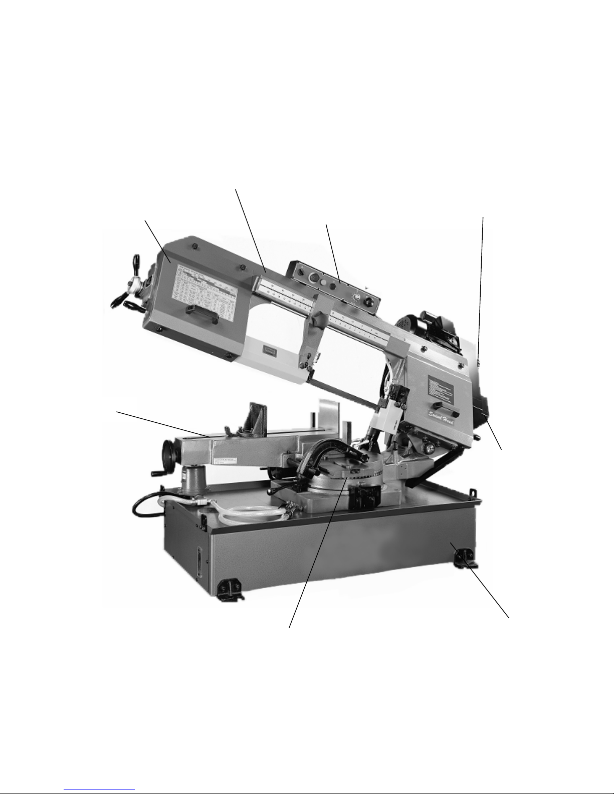
1.Overall Aspect
Vice
Angle Sale Base
Motor Cover
Change Speed Wheel
Tooth selection Control Panel
Body Frame
2

WARNING: FAILURE TO FOLLOW THESE RULES
MAY RESULT IN SERIOUS PERSONALINJURY
As with all machinery there are certain hazards involved with operation and use of the
machine. Using the machine with respect and caution will considerably lessen the
possibility of personal injury. However, if normal safety precautions are overlooked
or ignored, personal injury to the operator may result.
This machine was designed for certain applications only. We strongly recommend
that this machine NOT be modified and/or used for any application other than for
which it was designed. If you have any questions relative to its application DO NOT
use the machine until you contact with us and we have advised you.
Your machine might not come with a power socket or plug. Before using this
machine, please do ask your local dealer to install the socket or plug on the
Power cable end.
2.SAFETY RULES FOR ALL TOOLS
A. USER:
(1). WEAR PROPER APPAREL. No loose clothing, gloves, rings, bracelets, or
other jewelry to get caught in moving parts.
Non-slip footwear is recommended. Wear protective hair covering to contain long
hair.
(2). ALWAYS WEAR EYE PROTECTION. Refer to ANSLZ87.1 standard for
appropriate recommendations.
Also use face or dust mask if cutting operation is dusty.
(3). DON'T OVERREACH. Keep proper footing and balance at all times.
(4). NEVER STAND ON TOOL. Serious injury could occur if the tool is tipped or
if the cutting tool is accidentally contacted.
(5). NEVER LEAVE TOOL RUNNING UNATTENDED. TURN POWER OFF.
Don't leave tool until it comes to a complete stop.
(6). DRUGS, ALCOHOL, MEDICATION. Do not operate tool while under the
influence of drug, alcohol or any medication.
(7). MAKE SURE TOOL IS DISCONNECTED FROM POWER SUPPLY.
While motor is being mounted, connected or reconnected.
(8). ALWAYS keep hands and fingers away from the blade.
(9). STOP the machine before removing chips.
(10). SHUT- OFF power and clean the BAND SAW and work area before leaving
the machine.
3

B. USE OF MACHINE:
(1). REMOVE ADJUSTING KEYS AND WRENCHES. Form habit of checking
to see that keys and adjusting wrenches are removed from tool before turning it "on".
(2). DON'T FORCE TOOL. It will do the job better and be safer at the rate for
which it was designed.
(3). USE RIGHT TOOL. Don't force tool or attachment to do a job for which it was
not designed.
(4). SECURE WORK. Use clamps or a vise to hold work when practical. It's safer
than using your hand frees both hands to operate tool.
(5). MAINTAIN TOOLS IN TOP CONDITION. Keep tools sharp and clean for
best and safest performance. Follow instructions for lubricating and changing
accessories.
(6). USE RECOMMENDED ACCESSORIES. Consult the owner's manual for
recommended accessories. The use of improper accessories may cause hazards.
(7). AVOID ACCIDENTAL STARTING. Make sure switch is in “OFF” position
before plugging in power cord.
(8). DIRECTIONOF FEED. Feed work into a blade or cutter against the direction
of rotation of the blade or cutter only.
(9). ADJUST AND POSITION the blade guide arm before starting the cut.
(10). KEEP BLADE GUIDE ARM TIGHT, A loose blade guide arm will affect
sawing accuracy.
(11). MAKE SURE blade speed is set correctly for material being cut.
(12). CHECK for proper blade size and type.
(13). STOP the machine before putting material in the vise.
(14). ALWAYS have stock firmly clamped in vise before starting cut.
(15). GROUNDALL TOOLS. If tool is equipped with three-prong plug, it should
be plugged into a three-hole electrical receptacle. If an adapter is used to
accommodate atwoprong receptacle, the adapter lug must be attached to a known
ground. Never removed the third prong.
C. ADJUSTMENT :
MAKE all adjustments with the power off. In order to obtain the machine, precision
and correct ways of adjustment while assembling, the user should read the detailed
instruction in this manual.
4

D. WORKING ENVIRONMENT:
(1). KEEP WORK AREA CLEAN. Cluttered areas and benches invite accidents.
(2). DON'T USE IN DANGEROUS ENVIRONMENT. Don't use power tools in
damp or wet locations, or expose them to rain. Keep working area well-lighted.
(3). KEEP CHILEREN AND VISITIORS AWAY. All children and visitors
should be kept a safe distance from work area.
(4). DON’T install & use this machine in explosive, dangerous environment.
E. MAINTENANCE:
(1). DISCONNECT machine from power source when making repairs.
(2). CHECK DAMAGED PARTS. Before further using of the tool, a guard or
other part that is damaged should be carefully checked to ensure that it will operate
properly and perform its intended function. Check for alignment of moving parts,
binding of moving parts, breakage of parts, mounting, and any other conditions that
may affect its operation. A guard or other part that is damaged should be properly
repaired or replaced.
(3). DISCONNECT TOOLS before servicing and when changing accessories such
as blades, bits, cutters, etc.
(4). MAKE SURE that blade tension and blade tacking are properly adjusted.
(5). RE-CHECK blade tension after initial cut with a new blade.
(6). TO RPOLONG BLADE LIFE ALWAYS release blade tension at the end of
each workday.
(7). CHECK COOLANT DAILY Low coolant level can cause foaming and high
blade temperatures. Dirty coolant can clog pump, cause crooked. Rust, low cutting
rate and permanent blade failure. Dirty coolant can cause the growth of bacteria with
ensuing skin irritation.
(8). WHEN CUTTING MAGNESIUM NEVER use soluble oils or emulsions
(oil-water mix) as water will greatly intensify any accidental magnesium chip fire.
See your industrial coolant supplier for specific coolant recommendations when
cutting magnesium.
(9). TO PRNMT corrosion of machined surfaces when a soluble on is used as
coolant, pay particular attention to wiping dry the surfaces where fluid accumulates
and does not evaporate quickly, such as between the machine bed and vise.
F. SPECTIFIED USAGE:
This machine is used only for general metals cutting within the range of cutting
capacity.
5

G. NOISE:
A weighted sound pressure level : 80 dB.
H. SAFETY DEVICE:
Interlock switch on cutting area as soon as the cover of cutting area is open,
machine will stop at once witch the function of this switch. Do not remove this
switch from machine for any reason, and check its function frequently.
3.SPECIFICATION
MOTOR 2HP
Saw Blade Speed Variable Speed 60Hz 98 ~ 394FPM
Blade Size(mm) 27x0.9x3352
Dimension L x W x H (mm) 1880x720x1100
N.W / G.W (kgs) 390 / 430
Packing Measurement 1.930x864x1.257
○(mm/inch) 254mm / 10 “
0°□(mm/inch) 76x458mm / 3“x18“
○(mm/inch) 254mm / 10 “
+/- 45°□(mm/inch) 254x280mm / 10“x11“
○(mm/inch) 204mm / 8“
Cutting
Capacity
- 60°□(mm/inch) 127x204mm / 5“x8“
4.FEARTURES:
1. This machine is useful for cutting normal steel, steel pipe, and provides cutting
angle at + 60°and -45°by the swivel head.
2. A tooth selection label Ms provided on the machine for cutting reference.
3. Variable speed control gives convenient selection of speeds.
4. Hydraulic cylinder controls feeding volume and provides stable cutting.
5. Easy sliding the working table back and forth by loosing and fixing only two
bolts.
6. Quick positioning vise for clamping all sizes of work piece.
7. Chip pan underneath the working table prevents coolant fluid leaking and keep
floor dry.
6
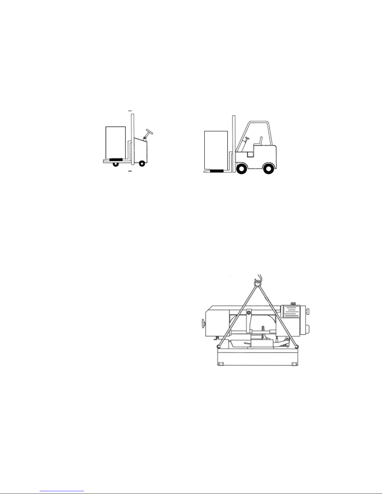
5.TRANSPORTATATION & INSTALLATION:
5-1.Unpacking
1. Transportation to desired location before unpacking, please use-lifting jack.
(Fig. B)
2. Transportation after unpacking, please use heavy duty fiber belt to lift up
the machine.
Fig. B
ALLWAYS KEEP PROPER FOOTING & BALANCE WHILE MOVING THIS
MACHINE.
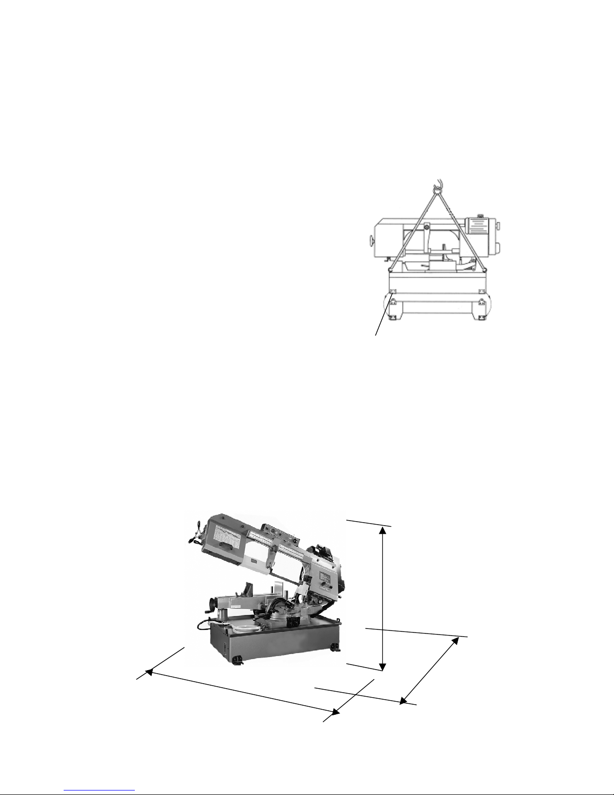
5-2.TRANSPORTATION OF MACHINE:
As this machine weights 430kgs it is recommended that the machine be transported
with help of lifting jack.
Transportation Recommendation:
1. Tighten all locks before operation.
2. Always keep proper footing & balance
while moving this machine, and only
use a heavy duty of fiber belt to lift the
machine as per Fig. 1.
3. TURN OFF the power before wiring
& be sure machine is properly
grounded. Overload & circuit breaker
are recommended for safety wiring.
4. Tighten 4 bolts to base holes after machine is
balanced. Fig. 1
5. Check carefully if the saw blade is running in counter-
clockwise direction if not, reverse the wiring per circuit diagram,
then repeat the running test.
6. Keep machine always out from sun, dust, wet, or raining area.
7
5-3.Installation:
(1) Always Keep proper footing & balance while moving this 430kgs machine. And
only use heavy-duty fiber belt to lift the machine as per Fig. (A).
(2) Hang the machine up, away from the floor, take away the 4 pads and assemble
them on the auxiliary stand. Fix the machine on the auxiliary stand and lock the
connection nut.
(3) Finish removing this wooden case / crate from
the machine. Unbolt the machine from the crate
bottom.
(4) Position & tighten 4 bolts into base holes
properly after machine in balance.
(5) Turn off the power before wiring & be sure
machine is in proper grounding. Overload &
circuit breaker is recommended for safety
B Fig.A
wiring.
(6) Keep machine always out from sun,
dust, wet, raining area.
5-4.CLEANING & LURICATING
(1) Your machine has been coated with a heavy grease to protect it in shipping.
This coating should be completely removed before operating the machine.
Commercial degreaser, kerosene or similar solvent may be used to remove the
grease from the machine, but avoid getting solvent on belts or other rubber
parts.
(2) After cleaning, coat all bright work with a light lubricant. Lubricate all points
in Fig 1. with a medium consistency machine oil.
6.MINIMUM ROOM SPACE FOR MACHINE OPERATION
116”
115”
78”
8

7. MAKE PROPER TOOTH SELECTION
For maximum cutting efficiency
and lowest cost per cut, it is important to
select the blade with the right number of
teeth per inch (TPI) for the material
being cut. The material size and shape
dictate tooth selection.
TOOTH
SELECTION
You need to consider:
The width of the cut - That is, the distance in the cut that each tooth must travel from
the point it enters the work-piece until it leaves the work-piece, and
1.The shape of the work-piece.
Squares, Rectangles, Flats (Symbol : ■)
Locate the width of cut on the chart. (Inches on the outer circle and
millimeters on the inner circle.) Select the tooth pitch on the ring marked
with the square shape which aligns with the width of cut.
EXAMPLE: 6" (150mm) square, use a 2/3 Vari-Tooth.
Round Solids (Symbol : ●)
Locate the diameter of your work-piece on the chart. Select the tooth pitch
on the ring marked with the round shape which aligns with the size of stock
you are cutting.
EXAMPLE: 4" (100mm) round, use a 3/4 Vari-Tooth.
Tubing, Pipe, Structural ( Symbol : O H ^ )
Determine the average width of cut by dividing the area of the work-piece
by the distance the saw blade must travel to finish the cut. Locate the
average width of cut on the chart. Select the tooth pitch on the ring marked
with the tubing and structural shape, which aligns with the average width
you are cutting.
EXAMPLE: 4"(100mm) outside diameter, 3"(75mm) inside diameter
tubing.
4"(100mm) OD=12.5 sq.ln. (79cm2)
3"(75 mm ) ID = 7.0 sq.ln. (44cm2)
Area = 5.5 sq.ln. (35cm2)
9

5.5 sq.ln. (35cm2) / 4" (100mm) distance =1.38(35mm) average width
1.38" (35mm), use a 4/6 Vari-Tooth
NOTE: The band speed and cutting rate recommendations presented on this
chart are approximations and are to be used as a starting point for most
applications. For exact sawing parameters' consult your saw blade supplier.
8. BI-METAL SPEEDS AND FEEDS
These figures are a guide to cutting 4"(100mm) material (with a 3/4 Vari-Tooth) when
using a cutting fluid.
Increase Band Speed: 15% When cutting 1/4"(6.4mm) material (l0/l4 Vari-Tooth)
12% When cutting 3/4"(19 mm) material (6/10 Vari-Tooth)
10% When cutting 1-1/4"(32 mm) material(5/8 Vari-Tooth)
5% When cutting 2-1/2" (64 mm) material(4/6 Vari-Tooth)
Decrease Band Speed: 12% When cutting 8"(200mm) material(2/3 Vari-Tooth)
BAND SPEEDMATERIAL ALLOY
ASTM NO. FT./MIN M/MIN
173,932 314 96
330,365 284 87
623,624 264 81
230,260,272 244 74
280,264,632,655 244 74
101,102,110,122,172 234 71
1751,182,220,510 234 71
625,706,715,934 234 71
630 229 70
Coppe
r
Alloy
811 214 65
1117 339 103
1137 289 88
1141,1144 279 85
1141 HI STRESS 279 85
Carbon
Steel
1030 329 100
1008,1015,1020,1025 319 97
1035 309 94
1018,1021,1022 299 91
Carbon
Steel
1026,1513 299 91
10
A36(SHAPES),1040 269 82
1042,1541 249 76
1044,1045 219 67
1060 199 61
1095 184 56
8615,8620,8622 239 73
4340,E4340,8630 219 67
Ni-Cr-Mo
Alloy Steel 8640 199 61
E9310 174 53
A-6 199 61
A-2 179 55
A-10 159 49
D-2 90 27
Tool Steel
H-11,H-12,H-13 189 58
420 189 58
430 149 46
410,502 140 43
414 115 35
431 95 29
440C 80 24
304,324 120 36
304L 115 35
347 110 33
316,316L 100 30
Stainless
Steel
416 189 58
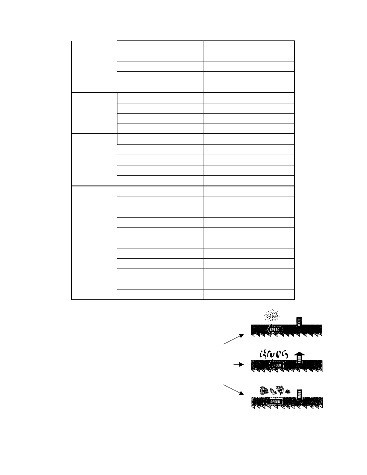
TELLTALE CHIPS
Chips are the best indicators of correct feed force. Monitor chip
information and adjust feed accordingly.
Thin or powdered chips – increase feed rate or reduce band
speed.
Burned heavy chips – reduce feed rate and or band speed.
Curly silvery and warm chips – optimum feed rate and band
speed.
11
9.USE OF MAIN MACHINE PARTS
9-1.POWER SYSTEM AND CONTROL PANEL
The electrical rating of your band saw is either with 230 volt-single phase,(or AC
power volt-3 phase), magnetic control.
Before connecting your machine to an electrical power system, be sure the motor
shaft is running in the correct direction.
We recommend that fuse with a 2 amp, dual element, time lag fuse, to be used to
supply power to all machines regardless of their electrical rating.
Refer to the electrical wiring diagram supplied with your machine for instructions
on how to connect saw to power source. Power must be cut off when wheel cover
is opened or during repairing.
Please check the moving direction of the blade. If the blade is moving in the
wrong direction, please re-connect the wire.
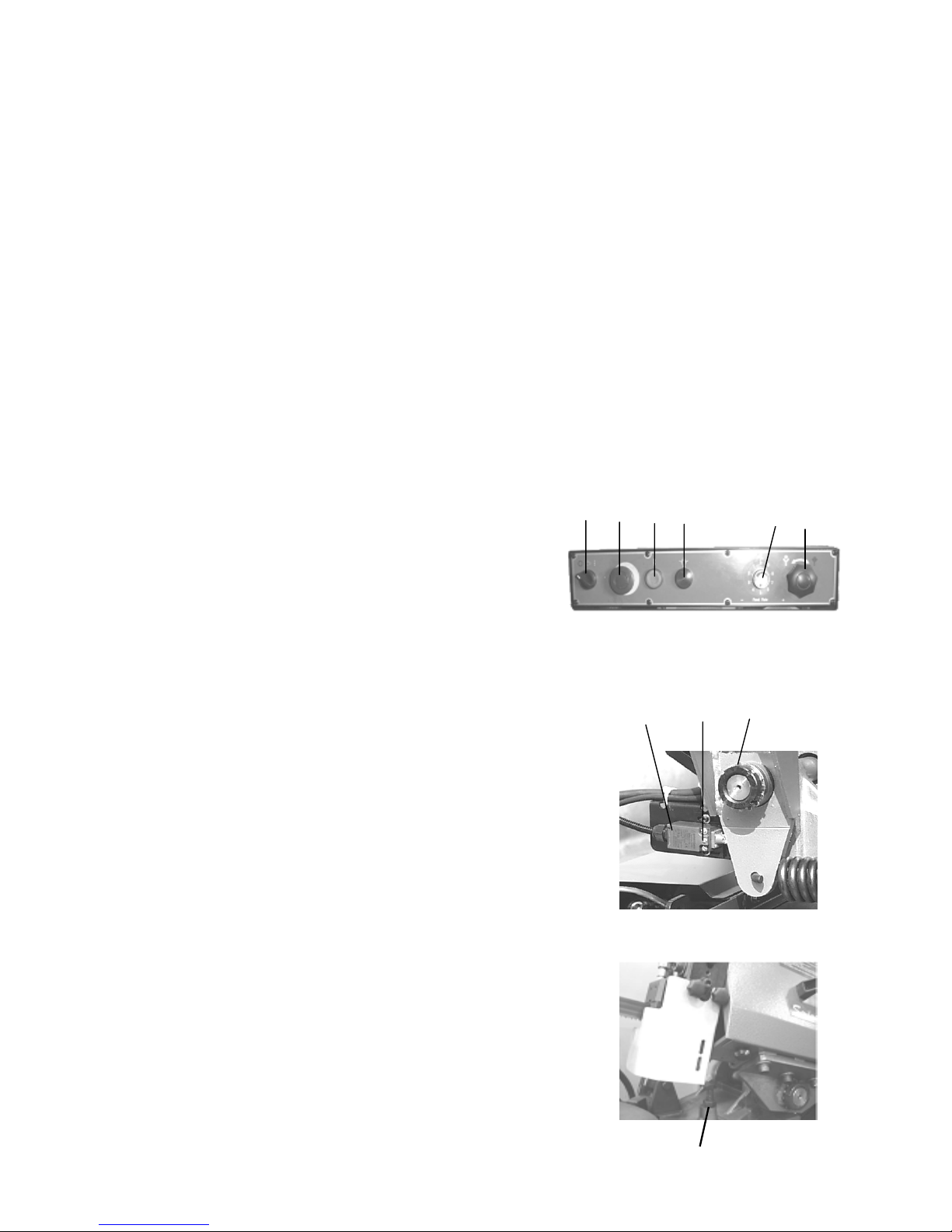
9-2.STARTING AND STOPPING MACHINE A B C D
Fig.3
K L M
A Fig.4
1. Light (D) will be on when power is connected.
Open hydraulic valve (F) when in operation.
2. Start the motor by pushing the start button (C),
Turn (A) ( 0-close,1-open) to open the coolant
system when saw blade is closing work piece.
When the cut is completed, turn off the coolant system (A)
3. Press emergency button (B) to shut-off the motor when
in emergent situation. Before next operation, release (B)
to get power.
4. An automatic shut-off limit switch is provided to stop
the motor when the cut is completed. The limit switch
(K) is controlled by button (L)(figure 3), which
contacts the rear cylinder (M) for shutting off the
motor and coolant system.
E F
9-3.ADJUSTING DOWNWARD TRAVEL OF SAW
ARM
The downward travel of the saw arm should be adjusted
so that when the saw arm is in the extreme downward
position, the teeth of the blade will not touch the table
surface. The stop screw (A) (Fig.4) is used to adjust the
distance between blade and table surface. After the
12
distance is adjusted, tighten lock nut.
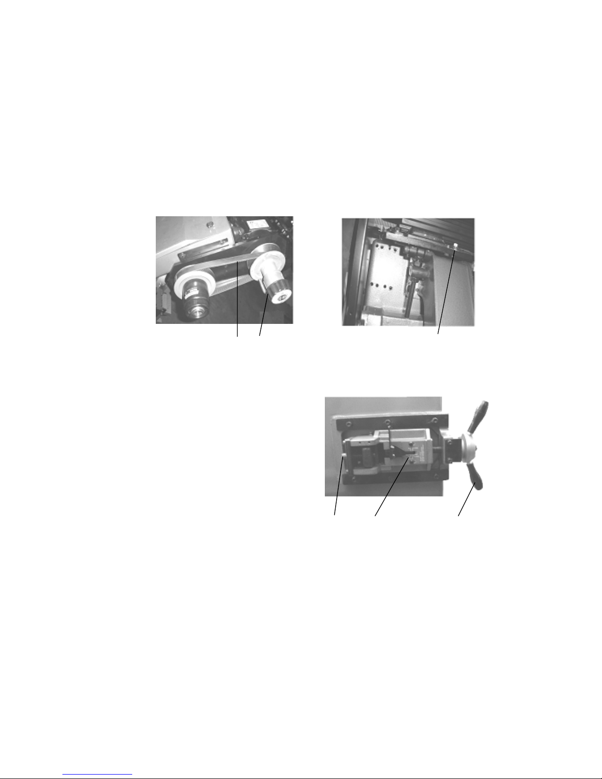
9-4.CHANGING SPEEDS AND ADJUSTING BELT TENSION
If the belt (B) (Fig 6) is too loose, Loosen screw nut (A)(Fig5) adjust the screw to
proper tension and lock the screw nut.
The cutting speed is controlled by speed change C (Fig 6). Turn it clockwise to
decrease the cutting speed and increase the cutting speed by turning
counter-clockwise.
Change speed always when motor is running, and be sure the belt cover is always
in locked position.
Fig.6 B C Fig.5 A
9-5.ADJUSTING BLADE TENSION AND BLADE TRACKING
C B Fig.7 A
To tension the blade, turn the blade tension
handle (A) (fig. 7) clockwise. A pointer and
tension scale (B) is located underneath the
wheel. The scale is graduated to indicate blade
tension of 20,000, 30.000 and 35,000 pounds
per square inch (psi). For carbon blades, the
blade should be tensioned at 20,000 psi. For
bi-metal blades (similar to the one supplied
with the machine), the blade should be
tensioned at 30,000 or 35,000 psi. Always release blade tension at the end of each
working day to prolong blade life. Make sure the blade is tensioned correctly before
checking or adjusting tracking. The blade is tracking properly when the back of the
blade is just lightly touching the wheel flanges of both wheels while the machine is
running. If the blade is not touching the wheel flanges, tighten or loosen screw C (fig.
7) until the blade tracks properly.
13

9-6.ADJUSTING CUTTING WIDTH
First loosen clamp knob (A) (fig. 8). Move the left blade guide bar
to the suitable position. Then tighten clamp knob (A).
A
Fig.8
9-7.ADJUSTING BLADE GUIDE ROLLER BEARINGS, CARBIDE BLADE
GUIDES AND BACK-UP BEARINGS
G
B
H
K
A
Fig.10 D
Before making the following adjustments, make sure
the blade is tracking and tensioned properly:
1.The back of the blade (A) (fig. 9) should F
ride against the back-up bearing (B).
To adjust, loosen set screw (C) and move E
the guide block (D) up or down, until it lightly
touches the back of the blade.
2.The saw blade (F) should also ride between and
lightly touch the two blade guide roller bearings
(E) and (B) (fig. 9)
Fig.9
C
The front bearing (E) (fig. 9) is mounted
on an eccentric, and can easily be adjusted
to suit blade thickness by loosening set
screw (G) and turning shaft (E).
3.The carbide blade guides (H) (fig 9)
should also be adjusted so they lightly touch the blade by loosening screw (K).
4. The blade guide roller bearings, carbide guides and backup bearing on holder
(fig 9 and 10) should be adjusted in the same manner.
5. Cutting chips on the blade will be cleared by the steel brush.
14

9-8.CLEARING THE CUTTTNG CHIP
Please use steel brush to clear the chip on the blade teeth (fig 11)
Fig.11
9-9.BLADE AND COOLING SYSTEM
The use of proper cutting fluid is essential to obtain
maximum efficiency from a band saw blade. The main cause
of tooth failure is excessive heat build-up. This is the reason
that cutting fluid is necessary for long blade life and high
cutting rates. cutting area and blade wheels should be kept
clean at all time.
A Fig.12
A
The rate of coolant flow is controlled by the stop valve lever
(A) (fig 12), which directs the coolant onto the blade.
The lever (A) is shown in the off position.
9-10.OPERATING AND ADJUSTING VISE
The work-piece is placed between the vise jaws with the
amount to be cut-off extending out past the blade. Your
machine is equipped with a "quick action" Vise jaw which
allows you to instantly position the moveable vise jaw B
(fig,14).
Fig.13
Simply turn hand-wheel A counterclockwise 1/2 turn and move the vise
jaw s to the desired
position. Then tighten the vise jaw B against the
work-piece by turning hand-wheel clockwise.
15
If an adjustment is necessary, proceed as follows: (fig.
13 and fig. 14) B
1. Loosen clamp handle and set screw .
Then turn hand-wheel A counterclockwise 1/2 turn.
2. Adjust the moveable vise jaw B to the suitable
Position and put the work-piece
Fig.14
3.Tighten clamp handle and set screw. Then turn hand-wheel clockwise
to fix the work-piece.
If the same cutting length can be used repeatedly on many
work-pieces, distance set rod can he used to set a fix
cutting length. Proceed as follows:
1. Let the top of the work-piece touch the distance set
rod.
2. Tighten vise jaw the fix the work-piece and get the
same cutting length. AFig.15
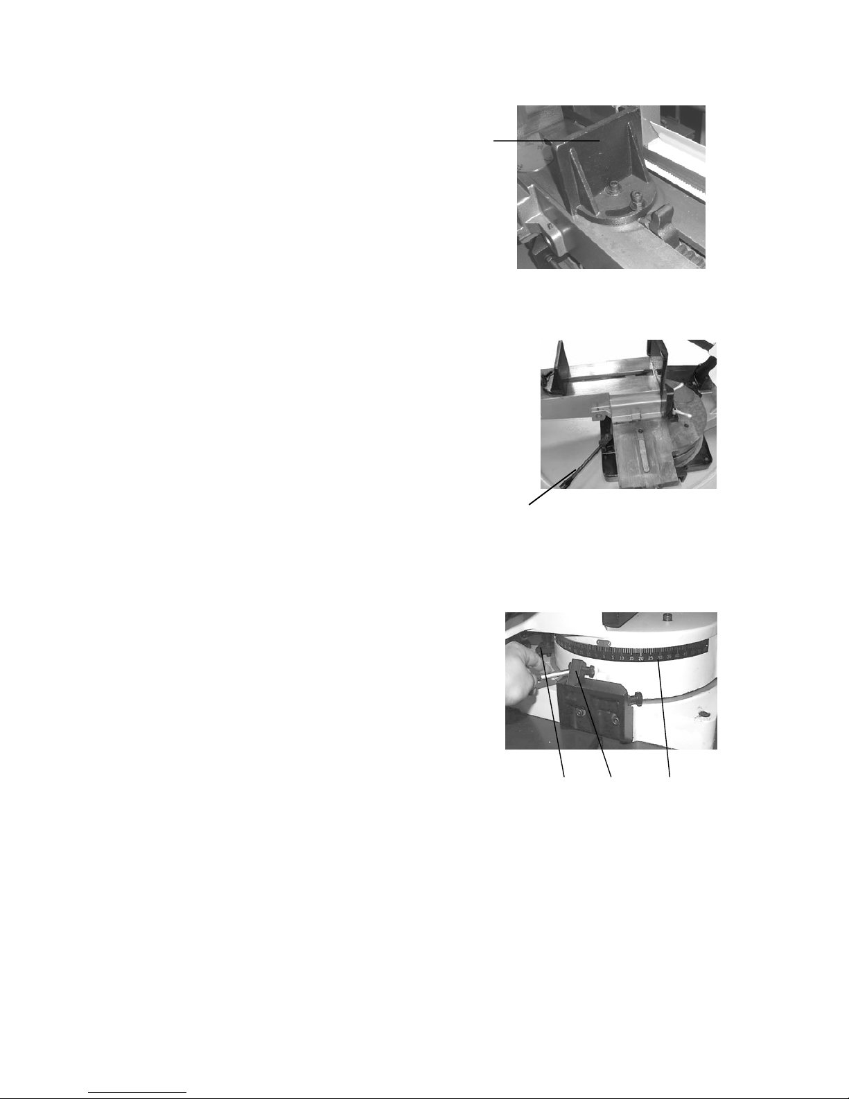
9-11.VARIABLE CUTTING ANGLE SELECTION
Please proceed as follows to obtain desired cutting angle. The swivel range is
from 60°clockwise to 45 °counter-clockwise.
1. Loosen grip A (fig. 15) Pull out bar C (fig. 16)
hold the bar.
2. Push to turn the swivel base to desired angle.
Refer to scale on D for degree.
3. Lock the grip B, then start the cutting.
Fig.16 B C D
16
9-12.REMOVING AND INSTALLING THE BLADE
Exchange of the saw blade:
1. Lift the saw arch to about the half height
and close the lowering valve.
2. Turn the saw arch to the right.
3. Disconnect the machine from the power
source.
4. Secure the metal belt saw against
unauthorized use.
5. Open the cover of the saw arch and disassemble the covers of the saw blade
guidance.
6. Loosen the saw blade tension by turning the hand-wheel anticlockwise.
7. First lift the saw blade of the left blade pulley and then of the driven blade pulley.
8. Clean the complete saw blade area.
9. Proceed the opposite way to assemble the new saw blade. Make sure that the saw
blade is positioned correctly onto the blade pulleys and in the blade guidance
bearings.
10. Make sure that the saw teeth show to the right direction. The saw teeth must
show to the driving motor.
11. Retighten the saw blade.
12. If required, readjust the saw blade guidance.
13. Close the saw blade housing.
14. Proceed a trial run.
15. Remount all the protective covers.
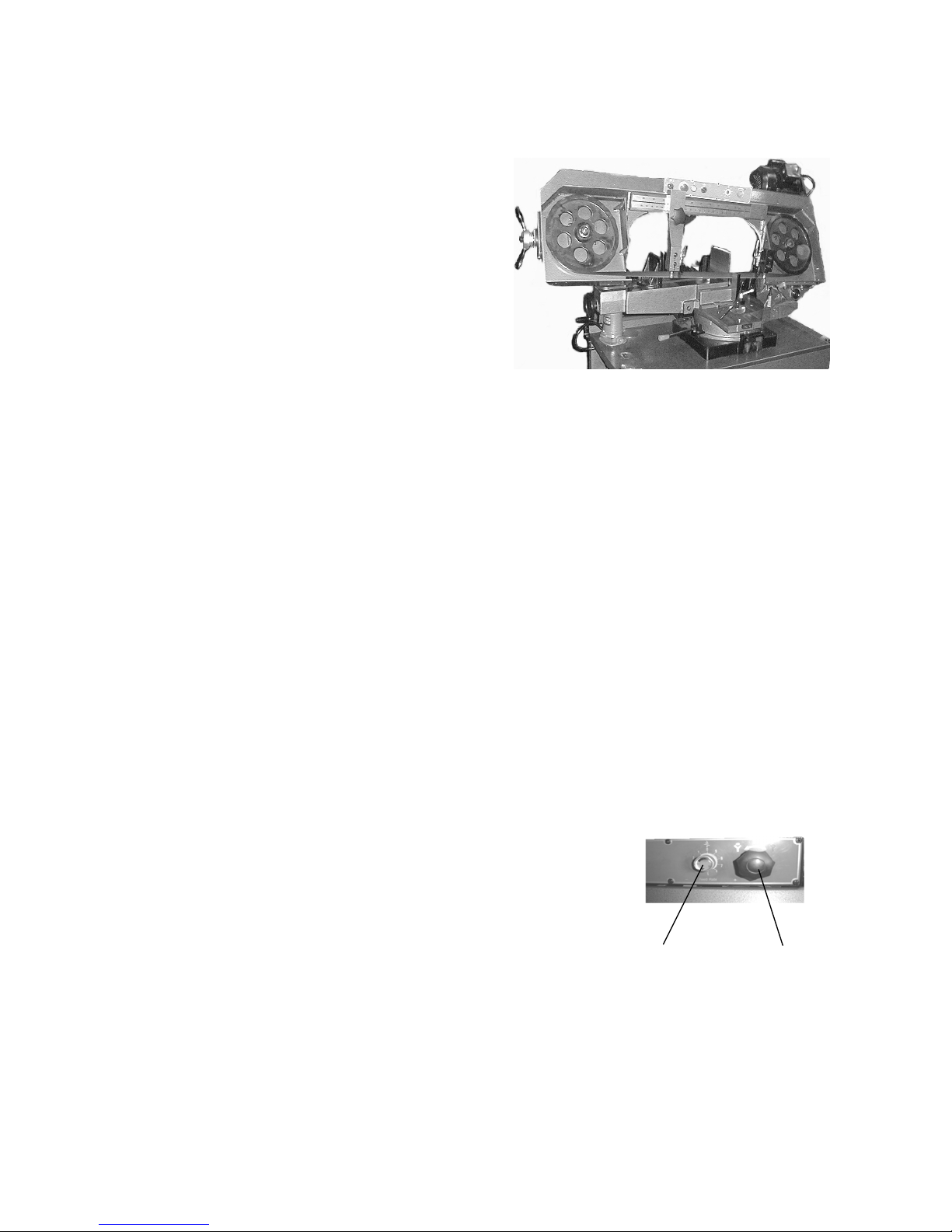
9-13.HYDRAULIC SYSTEM
D Fig.18 E
The hydraulic system on this machine consists of a hydraulic
cylinder, which is operated by a needle valve. The saw frame is
to be automatically raised up by the hydraulic movement, and as
this is done, oil passes to the underside of the piston. The
restricted flow is regulated by the feed rate control knob and governs the speed the
saw frame lowers If turn the valve (D) (fig 18) clockwise, the descending speed of the
saw frame will decrease If turn the valve counterclockwise, the descending speed of
the saw frame will increase. If user want to stop the descending saw frame, fasten the
valve (E).
17
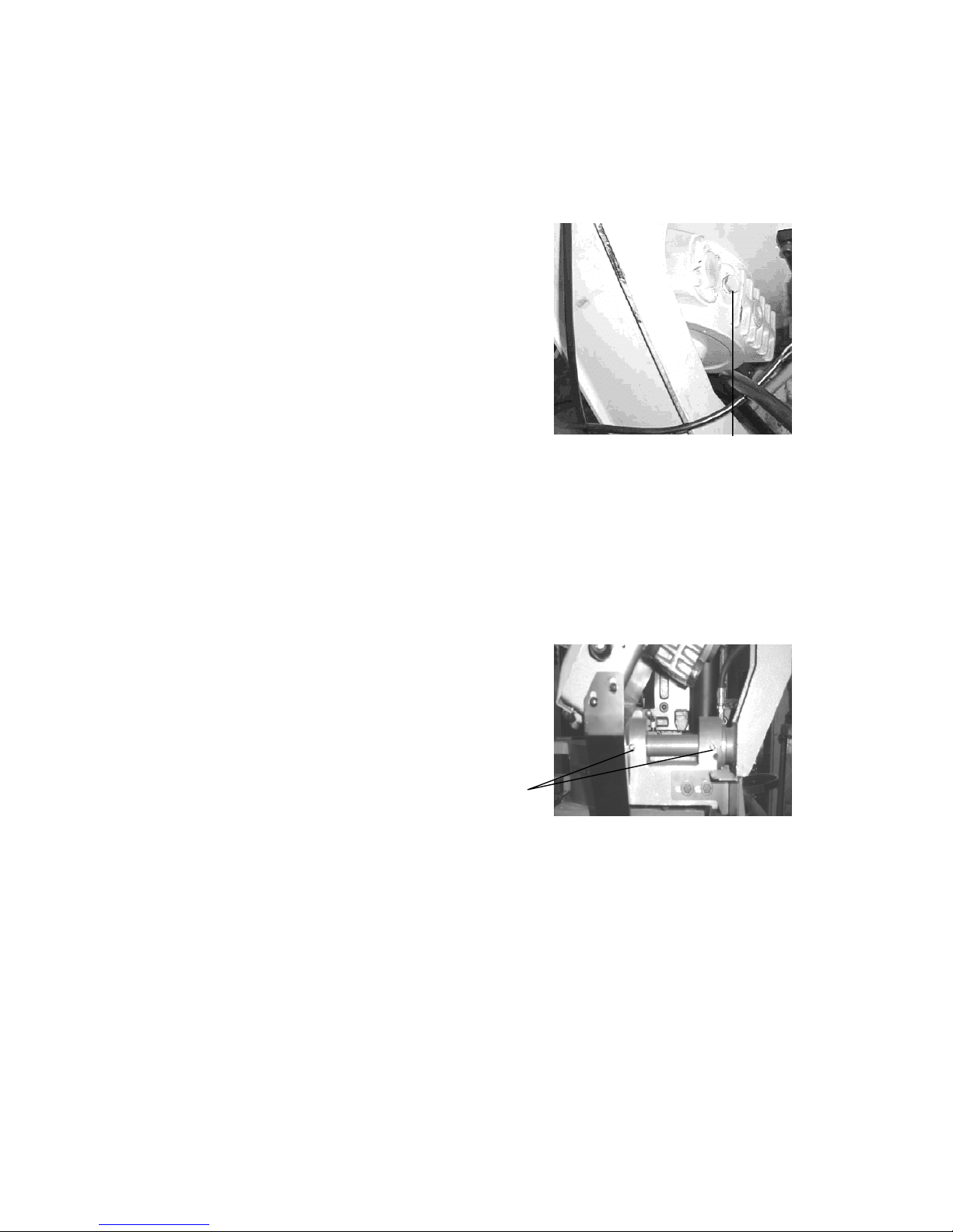
9-14.GEAR BOX
The gearbox should be drained and refilled after the first 50 hours of use and
thereafter every 5 months, with Mobil Synthetic Gear Oil, SHC-636, ISO Viscosity
Grade 680. This oil meets or exceeds American Gear Manufacturers Association
(AG.M.A.) #8 compounded Cylinder Oil
specifications. This oil is available through
Grainger's in 1 quart bottles as number SW061.
Fig.19 A
To change the gear oil, proceed as follows:
1. Run the machine for 10 minutes to warm up the
gearbox.
2. Disconnect the machine from the power source.
3. Raise the saw arm to its maximum position and
close the feed rate control knob.
4. Drain the gearbox by removing the screw away
from the oil-out hole (A) (fig. 19).
5. Replace a screw and lower the saw arm to its lowest position.
6. Open the oil-in hole and fill the gearbox with oil
7. Close the oil-in hole.
9-15.PIVOT
Occasionally lubricate the pivot using waterproof
grease at the fitting ( C) (fig 20)
C
Fig.20
18
Table of contents
Popular Saw manuals by other brands


DeWalt
DeWalt DWE575 instruction manual

Erbauer
Erbauer EMCS650 Original instructions

Powermatic
Powermatic 64B operating instructions

Makita
Makita 5800NB instruction manual

Einhell Global
Einhell Global HKL-G 1400 operating instructions

Swarts Tools
Swarts Tools SW1075 Instruction booklet and warranty information