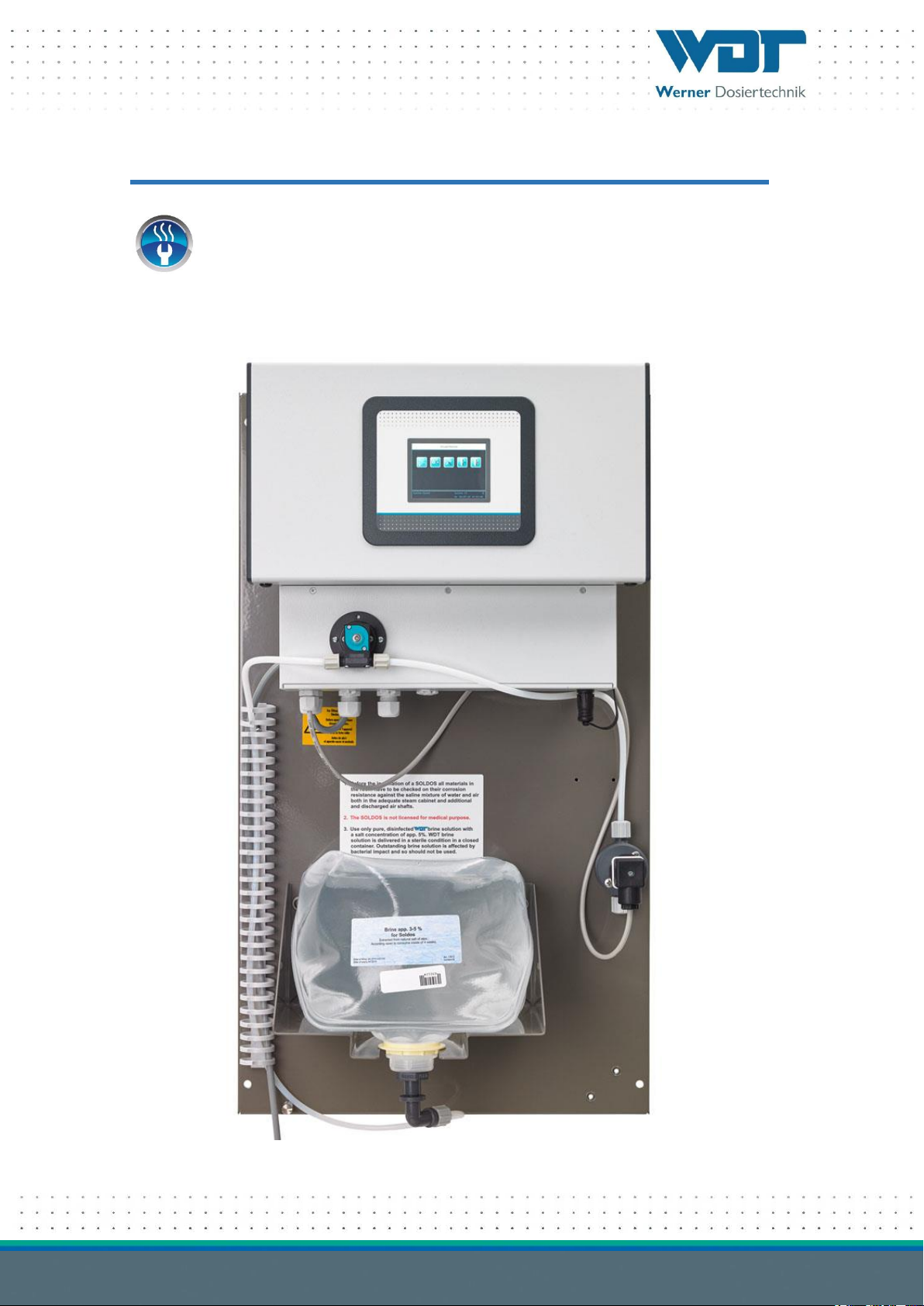
Brine Nebulization System, Type Soldos V3
Index: 03 Change date: 01/03/2017 Operating instructions no.: BA DW 005-03 Soldos V3 EN.docx Page 2 of 70
Table of contents
1Information regarding these instructions / general information ................................................................ 4
1.1 Scope of validity ................................................................................................................................................4
1.2 Target group .....................................................................................................................................................4
1.3 Symbols used.....................................................................................................................................................4
1.4 Warranty ..........................................................................................................................................................5
1.5 Further information...........................................................................................................................................6
2Safety ........................................................................................................................................................ 7
2.1 Appropriate use ................................................................................................................................................7
2.2 Safety instructions: ............................................................................................................................................7
3Product description - delivery scope.......................................................................................................... 8
3.1 Delivery scope / accessories .............................................................................................................................8
3.2 Product description .........................................................................................................................................10
3.3 Identification of the device / name plate..........................................................................................................10
3.4 Technical data..................................................................................................................................................11
3.5 Transport / storage.........................................................................................................................................11
4Assembly................................................................................................................................................. 12
4.1 Selecting the place of installation......................................................................................................................12
4.2 Assembly information (installation suggestion) ..............................................................................................12
4.3 Mechanical installation .....................................................................................................................................14
4.4 Hydraulic installation .......................................................................................................................................15
4.5Electrical installation ........................................................................................................................................16
5Initial operation ....................................................................................................................................... 17
5.1 Commissioning - comments.............................................................................................................................17
5.2 Commissioning - procedure.............................................................................................................................17
6Operation / handling............................................................................................................................... 27
6.1 General ...........................................................................................................................................................27
6.2 Controller - software.......................................................................................................................................27
6.3 The main menu ...............................................................................................................................................30
6.4 Operating modes menu...................................................................................................................................32
6.5 Settings menu..................................................................................................................................................42
6.6 Service menu...................................................................................................................................................50
6.7 Login ...............................................................................................................................................................54
6.8 Logout.............................................................................................................................................................54
6.9 Optional functions ...........................................................................................................................................54
6.10 Top up consumables........................................................................................................................................54
7Maintenance, service, faults ..................................................................................................................... 55
7.1 Device maintenance.........................................................................................................................................55
7.2 Regular water inspection .................................................................................................................................55
7.3 Fault removal / fault codes.............................................................................................................................55
8Shutting down –Storage –Disposal........................................................................................................ 59
8.1 General ...........................................................................................................................................................59
9Documents.............................................................................................................................................. 60
9.1 Declaration of conformity ...............................................................................................................................60
9.2 Terminal plans .................................................................................................................................................61
9.3 Commissioning protocol / instruction .............................................................................................................63
9.4 Operating data sheet .......................................................................................................................................64
9.5 Maintenance protocol......................................................................................................................................66
9.6 Spare parts list, wearing parts list, consumables list .........................................................................................68
10 Appendices.............................................................................................................................................. 70


 owner's manual")