8
Boiler Heat Exchanger Descaling/Cleaning
To Descale/Clean the boiler the following is needed:
• Boiler Manufacturer Maintenance Instructions
Should there be a discrepancy or conict with these instructions, follow the Boiler Manufacturer’s instructions.
• Descaling/cleaning solution
• 2 hoses
• Bucket
• Ability to activate the NBP System Circulator
T
O
B
U
C
K
E
T
T
O
B
U
C
K
E
T
SUPPLYRETURN
F
L
O
W
F
L
O
W
SUPPLYRETURN
SUPPLYRETURN
C
O
N
N
E
C
T
T
O
W
A
T
E
R
S
O
U
R
C
E
T
O
B
U
C
K
E
T
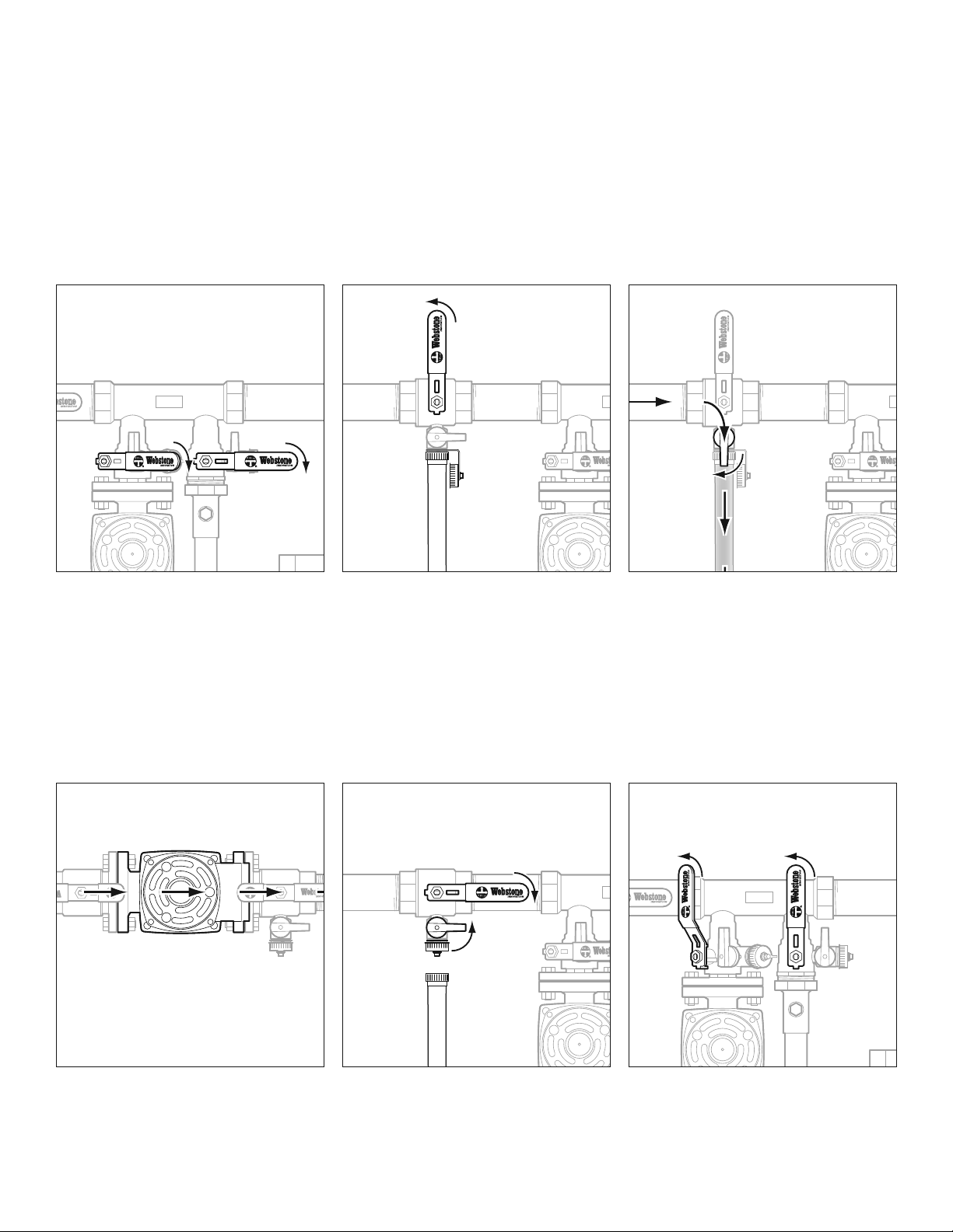
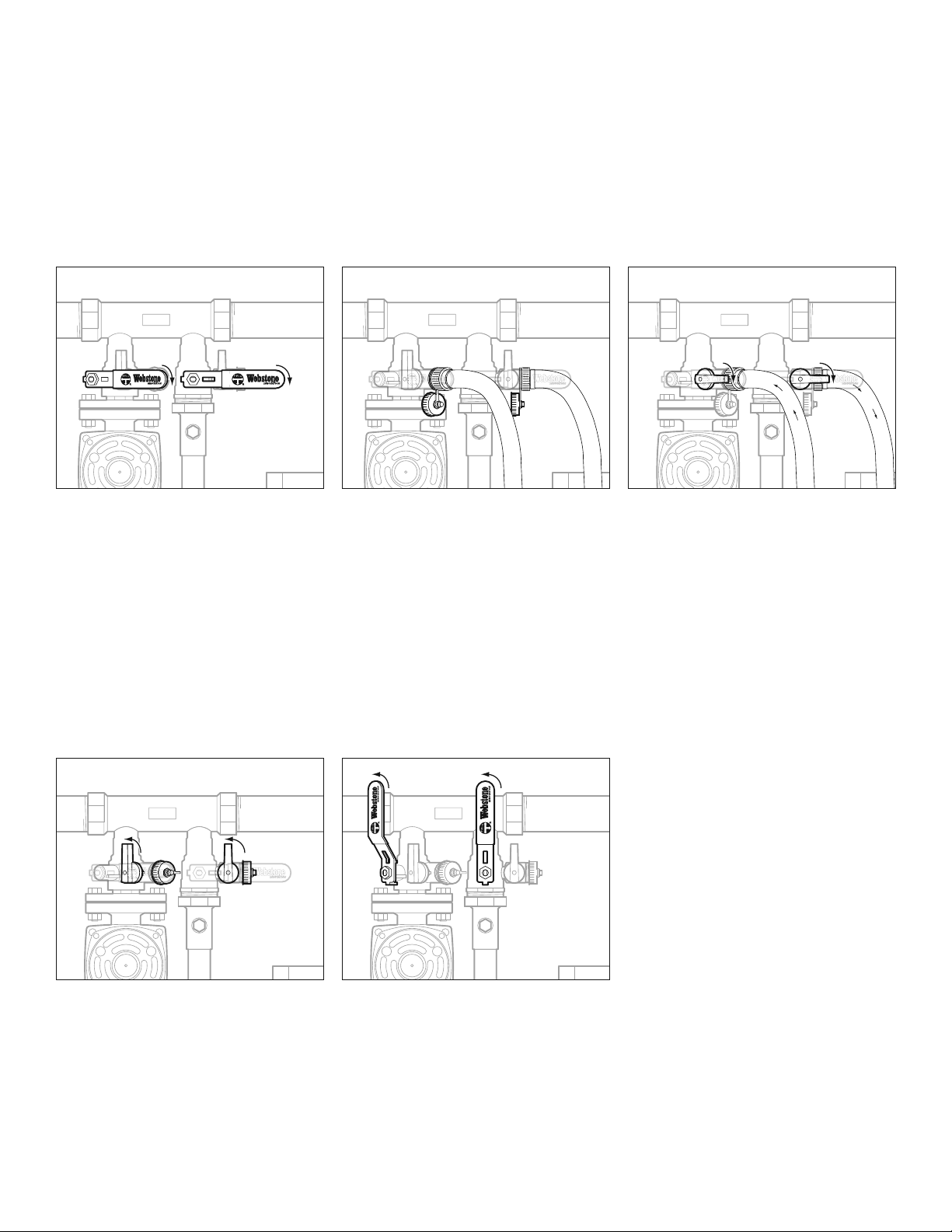
1. Turn the lever handles on both
Hydro-Core ball valves so that they
are parallel to the ange. The T-Flow
handle logo indicates the ow pattern
inside the valve. The logo should
indicate that ow can go through the
purging valve and both the supply
and return piped assemblies.
2. Remove both purging valve caps.
3. Connect one of the hoses to the
system return purging valve (located
above the ange connection).
4. Connect the other hose to the
system supply purging valve.
5. Fill a 5 gallon bucket with the boiler
manufacturer’s recommended
cleaning/descaling solution.
6. Place the ends of both hoses
into bucket of solution.
7. Turn the drain handles on both the
system return & system supply
purging valves into the open position
(drain handles parallel with the ange).
8. Turn on the circulator pump in the
NBP Loop and allow the solution to
ow into and out of the NBP System.
9. See boiler manufacturer maintenance
instructions to determine when
system is sufciently cleaned.
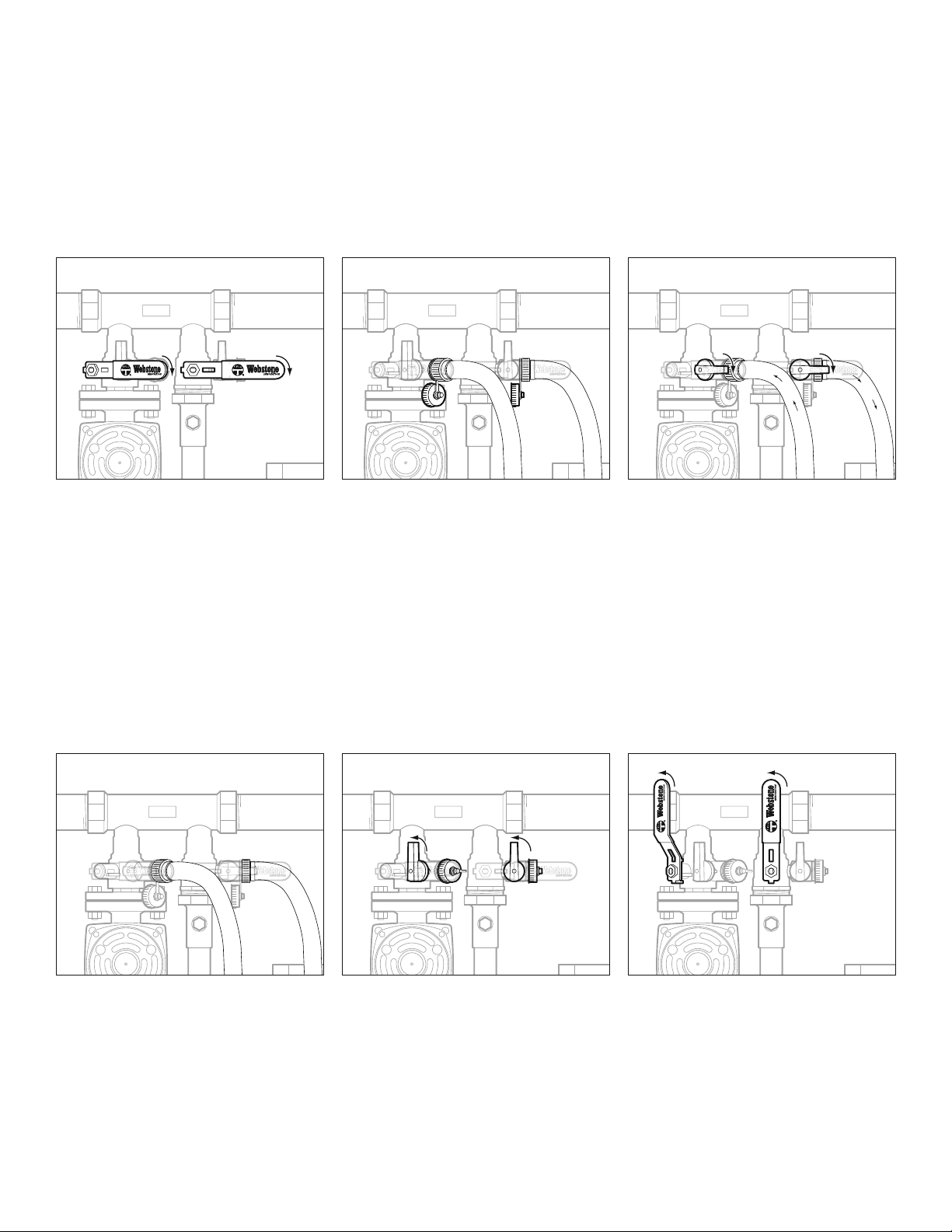
10. When boiler is sufciently cleaned,
remove the hose connected to the
system return’s purging valve from
the bucket (system return is the
side with the ange connection).
11. Connect system return purging
valve hose to a water source.
12. Turn on the water source and allow
water to ow into the circulator to
purge the entire loop with fresh water.
If needed, turn on the circulator pump
to force water through the system.
13. Once the solution has been
purged out in the bucket and the
drainage from the hose on the
system supply purging valve runs
clear, turn off the circulator.
14. Close the two purging valves, remove
the hoses, and replace the caps.
15. The boiler and NBP loop will now
be lled with clean fresh water.
If a glycol solution is preferred,
repeat steps 2–14 above with glycol
rather than a descaling solution.
16. Return the lever handled ball valves
to their normal operating position
(handles perpendicular to the ange).
The Isolator®and Pro-Pal®are registered trademarks of Webstone Company, Inc.
© 2011 Webstone Company
HCM-0112