manuals.online logo
Brands
  1. Home
  2. •
  3. Brands
  4. •
  5. IBC
  6. •
  7. Boiler Supplies
  8. •
  9. IBC P-271 User manual

IBC P-271 User manual

120-284R3 |4/4/2018 www.ibcboiler.com │ 1
P-271 Safety Ignition Module+ (SIM+) replacement kit
The kit replaces an existing SIM+ module.
IBC Part # Description Boiler Model
P-271 Safety Ignition Module+ (SIM+) SL 10-85 G3, SL 14-115 G3, SL 20-160 G3, SL 30-199 G3
Warning
This kit shall be installed by a qualified service agency in
accordance with the manufacturer’s instructions and all applicable
codes and requirements of the authority having jurisdiction. If the
information in these instructions is not followed exactly, a fire, an
explosion or production of carbon monoxide may result causing
property damage, personal injury or loss of life. The qualified service
agency is responsible for the proper installation of this kit.
Kit contents:
A. SIM+ module configured to Fenwal mode - # 500-078
B. 2 x screws - 6-32 x 5/8" - # 150-015
Note
For increased reliability, we recommend that you replace the ignitor (purchased separately) at the same time as
the SIM. However, ignitors with low running hours can be reused. See Replacing the ignitor on page 2.
Installation Instructions
Installing a SIM+
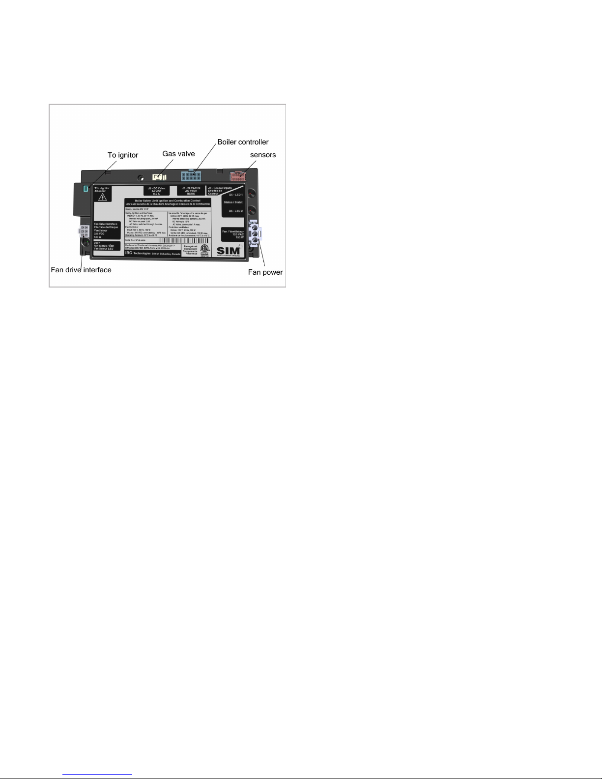
Figure 1 SIM connections - SL 10-85 G3, SL 14-115 G3, SL
20-160 G3, SL30-199 G3 series boilers
1. Disconnect the power to the boiler and close the
gas shut-off valve.
All the module’s connector plugs, except the
ignition lead, have retaining clips.
2. Note the position of the retaining clips for each
plug. The retaining clips must be depressed and
properly released before the connectors can be
unplugged.
3. Unplug all the connectors from the module.
4. Check that the wire connections are still solid and
secure.
5. To remove the existing module, hold it in place as
you unscrew the two mounting screws. Retain the
screws.
6. Position the new module, so that the mounting
holes align.
7. Insert the screws and lightly tighten to secure the
module in place.
8. Plug the connectors into their respective sockets
(see image above), ensuring that the retaining
2 │ www.ibcboiler.com
clips click into place properly. Each wire
connector plug should fit snugly into a socket.
9. (Optional) To replace the ignitor:
a. Unscrew the two Phillip head screws
holding the ignitor in place.
b. Position the new ignitor and gasket in
place, and attach using the two ignitor
screws supplied with the kit.
10. Leaving the gas off, restore power to the boiler.
If the ignitor was replaced, you should
pressurize the combustion chamber to check
for leaks around the ignitor gasket. The way to
pressurize the combustion chamber is to put
the fan into vent test mode that will drive the
fan into high speed.
11. To perform the leak test:
a. Apply an approved leak solution around
the ignitor gasket.
b. Remove any call for heat.
c. From the touchscreen controller's Main
Menu go to Diagnostics>Fan
Operation>Press the Vent Test On/Off
button to drive the fan into high speed.
d. When finished, press the On/Off again,
and wipe off the excess solution.
12. Leaving the gas off, initiate a call for heat.
13. Look through the sight glass to check that a
spark is present during the ignition trial.
14. If the spark looks bright and stable, turn on the
gas and allow the boiler to go through another
trial for ignition. It should light off smoothly and
quietly.
Replacing the ignitor
1. Disconnect the power to the boiler and close
the gas shut-off valve.
2. Remove the ignition wire and ground wire from
the ignitor.
3. Remove the two mounting screws holding the
ignitor in place, and retain them.
4. Remove the existing ignitor and gasket, and
replace with the new parts.
5. Install the retained mounting screws and firmly
tighten.
6. Re-attach the ignition wire and ground wire from
the module.
If the ignitor was replaced, you should pressurize
the combustion chamber to check for leaks
around the ignitor gasket. The way to pressurize
the combustion chamber is to put the fan into vent
test mode that will drive the fan into high speed.
7. To perform the leak test:
a. Apply an approved leak solution around the
ignitor gasket.
b. Remove any call for heat.
c. From the touchscreen controller's Main
Menu go to Diagnostics>Fan
Operation>Press the Vent Test On/Off
button to drive the fan into high speed.
d. When finished, press the On/Off again, and
wipe off the excess solution.
8. Leaving the gas off, initiate a call for heat.
9. Look through the sight glass to check that a spark
is present during the ignition trial.
10. If the spark looks bright and stable, turn on the
gas and allow the boiler to go through another trial
for ignition. It should light off smoothly and
quietly.
120-284R3 |4/4/2018 www.ibcboiler.com |3

Other IBC Boiler Supplies manuals

IBC EX 850 User manual

IBC

IBC EX 850 User manual

IBC P-175 User manual

IBC

IBC P-175 User manual

IBC P-807 User manual

IBC

IBC P-807 User manual

IBC P-153B Guide

IBC

IBC P-153B Guide

IBC P-1609 User manual

IBC

IBC P-1609 User manual

IBC IBT 25 Installation instructions

IBC

IBC IBT 25 Installation instructions

IBC P-1201 User manual

IBC

IBC P-1201 User manual

IBC SFC-125 Quick start guide

IBC

IBC SFC-125 Quick start guide

IBC SL 80-399 User manual

IBC

IBC SL 80-399 User manual

Popular Boiler Supplies manuals by other brands

TriangleTube PSRKIT41 manual

TriangleTube

TriangleTube PSRKIT41 manual

EFFIKAL RVGP-KS-BKF Series installation instructions

EFFIKAL

EFFIKAL RVGP-KS-BKF Series installation instructions

Kemper 612 07 001 installation manual

Kemper

Kemper 612 07 001 installation manual

DeDietrich EA 30 manual

DeDietrich

DeDietrich EA 30 manual

U.S. Boiler Company SteamMax STMX100 quick start guide

U.S. Boiler Company

U.S. Boiler Company SteamMax STMX100 quick start guide

Field Controls SWGII-5 manual

Field Controls

Field Controls SWGII-5 manual

Immergas 3.021378 manual

Immergas

Immergas 3.021378 manual

TriangleTube PTRKIT301 installation instructions

TriangleTube

TriangleTube PTRKIT301 installation instructions

Hobart G1009 Installation, Use and Maintenance Instruction

Hobart

Hobart G1009 Installation, Use and Maintenance Instruction

Field Controls CAS-34U manual

Field Controls

Field Controls CAS-34U manual

GESTRA SRL 63-a Original Installation Instructions

GESTRA

GESTRA SRL 63-a Original Installation Instructions

Vapac VapaNet Operation manual

Vapac

Vapac VapaNet Operation manual

Immergas VICTRIX PRO 35 V2 SET manual

Immergas

Immergas VICTRIX PRO 35 V2 SET manual

Miura MP1-200 installation manual

Miura

Miura MP1-200 installation manual

TriangleTube PSRKIT44 manual

TriangleTube

TriangleTube PSRKIT44 manual

manuals.online logo
manuals.online logoBrands
  • About & Mission
  • Contact us
  • Privacy Policy
  • Terms and Conditions

Copyright 2025 Manuals.Online. All Rights Reserved.