2| Contents
Logamax plus GB142-24/30/45/606 720 810 045 (2013/12)
Contents
1 Safety considerations . . . . . . . . . . . . . . . . . . . . . . . . . . . . . . . . . 2
1.1 Application purpose . . . . . . . . . . . . . . . . . . . . . . . . . . . . . 2
1.2 Explanation of Symbols . . . . . . . . . . . . . . . . . . . . . . . . . . 2
1.3 Additional symbols . . . . . . . . . . . . . . . . . . . . . . . . . . . . . . 2
1.4 Observe the following warnings . . . . . . . . . . . . . . . . . . . 2
2 Scope of delivery . . . . . . . . . . . . . . . . . . . . . . . . . . . . . . . . . . . . . 2
3 Installation . . . . . . . . . . . . . . . . . . . . . . . . . . . . . . . . . . . . . . . . . . . 3
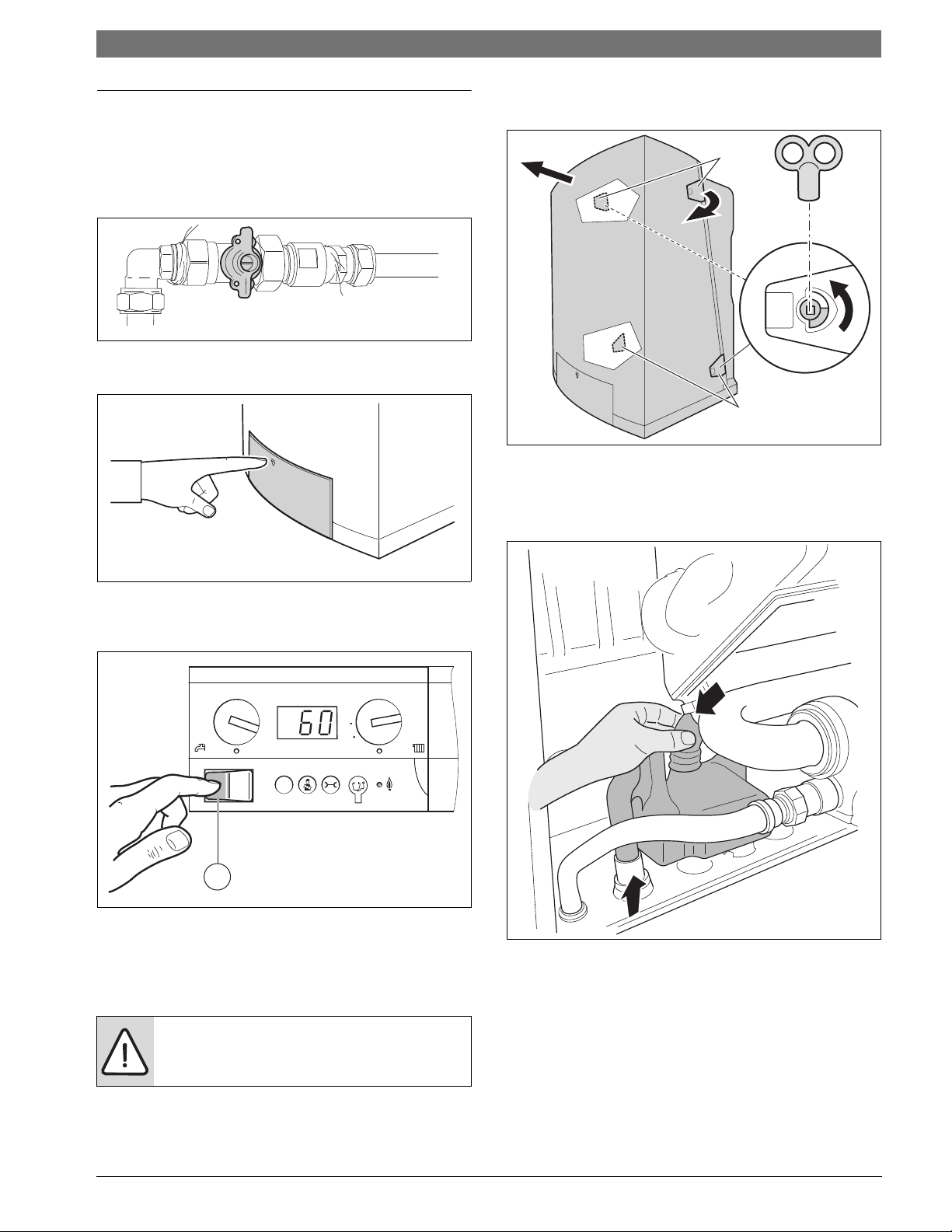
3.1 Shutting down the appliance . . . . . . . . . . . . . . . . . . . . . . 3
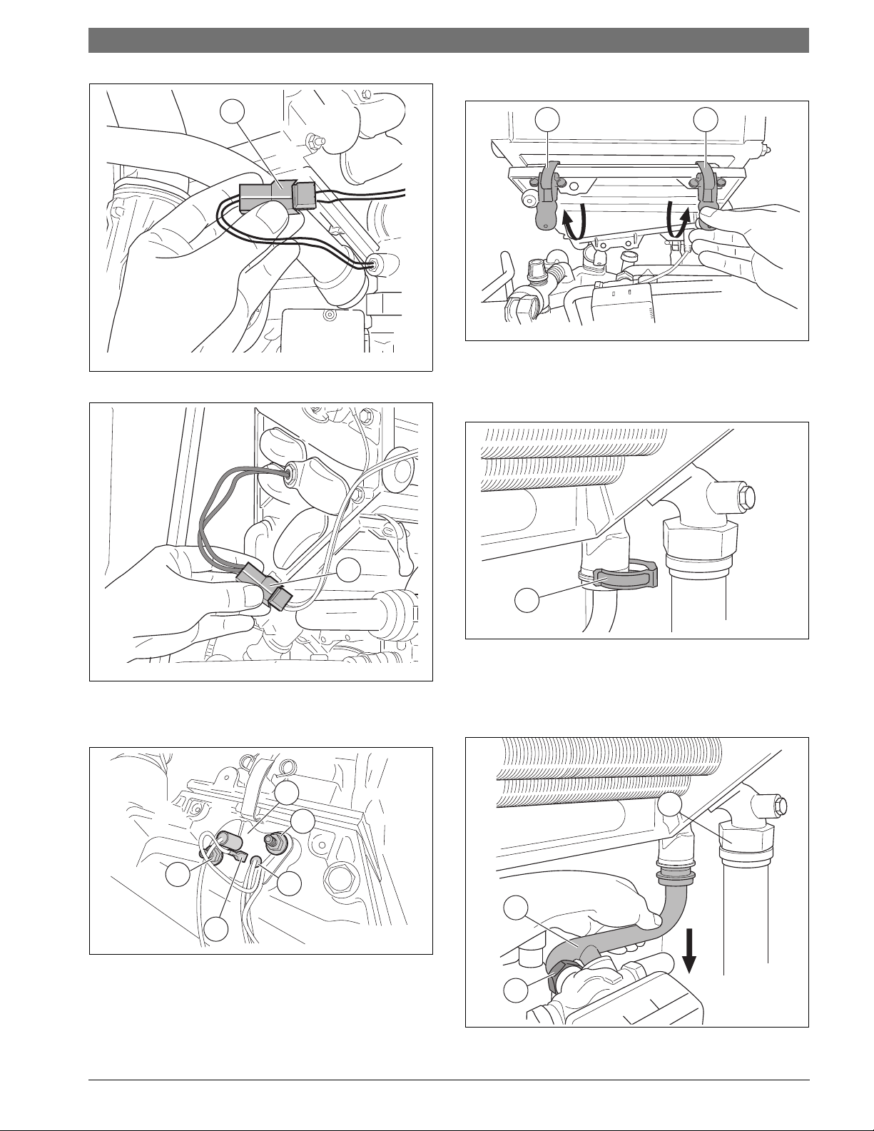
3.2 Removing the condensate trap . . . . . . . . . . . . . . . . . . . . 3
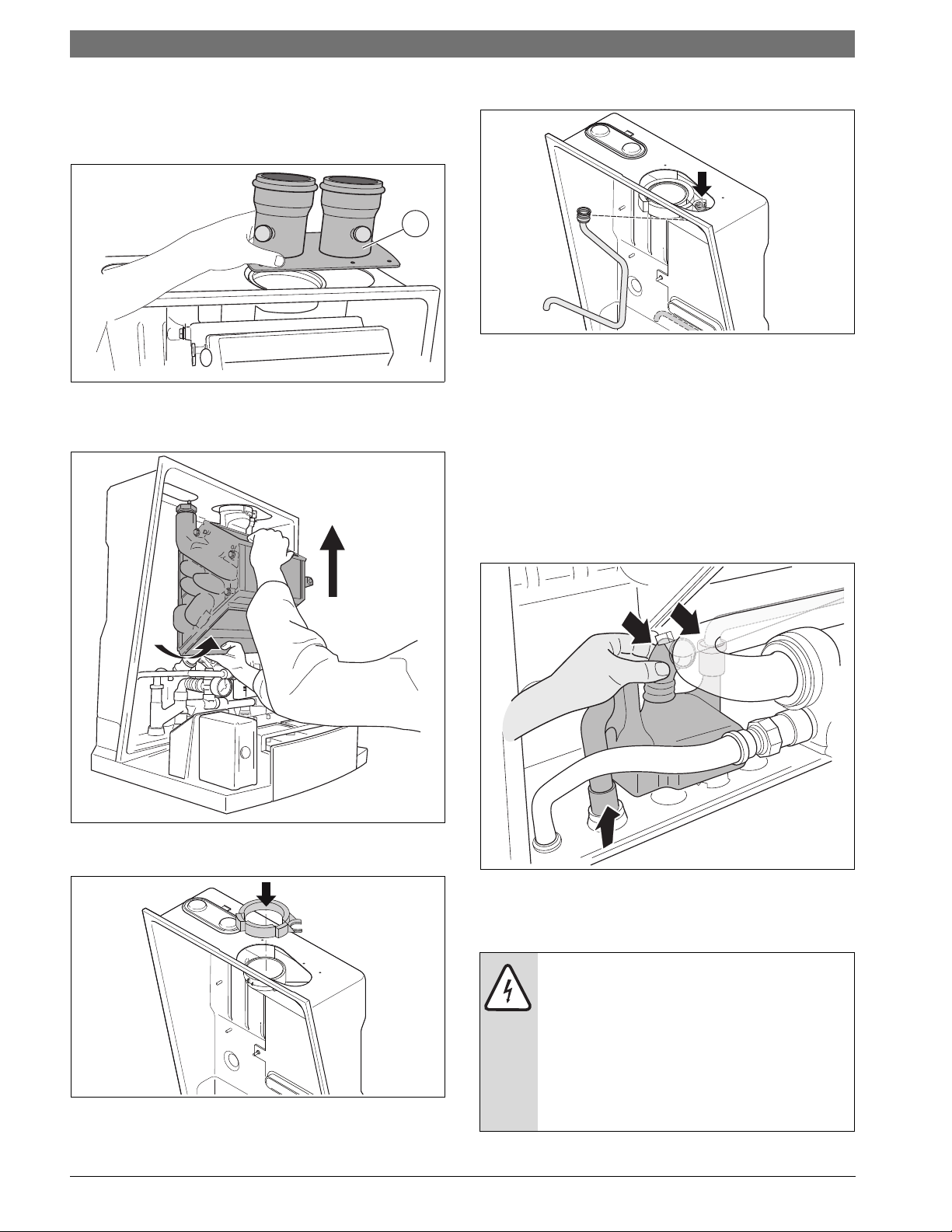
3.3 Removing the heat exchanger . . . . . . . . . . . . . . . . . . . . . 4
3.4 Mounting the new condensate trap and flue gas
adapter . . . . . . . . . . . . . . . . . . . . . . . . . . . . . . . . . . . . . . . 6
3.5 Testing for gas leaks . . . . . . . . . . . . . . . . . . . . . . . . . . . . . 6
3.6 Filling the appliance . . . . . . . . . . . . . . . . . . . . . . . . . . . . . 7
3.7 Start up the appliance . . . . . . . . . . . . . . . . . . . . . . . . . . . 7
1 Safety considerations
The conversion shall be carried out by a manufacturer’s authorized
representative, in accordance with the requirements of the
manufacturer, provincial or territorial authorities having jurisdiction and
in accordance with the requirements of the CAN/CGA-B149.1 or
CAN/CGA-B149.2 installation codes.
For use in Canada the conversion shall be carried out in accordance with
the requirements of the provincial authorities having jurisdiction and in
accordance with the requirements of the CAN/CGA-B149.1 and
CAN/CGA-B149.2 Installation Code. See also E.I.V.
Please observe the following safety instructions.
1.1 Application purpose
This kit and these instructions are to provide the Logamax plus
GB142-24/30/45/60 with an internal condensate bypass.
1.2 Explanation of Symbols
Warning symbols
Signal words indicate the seriousness of the hazard in terms of the
consequences of not following the safety instructions.
•NOTICE indicates possible damage to property or equipment, but
where there is no risk of injury.
•CAUTION indicates possible injury.
•WARNING indicates possible severe injury.
•DANGER indicates possible risk to life.
Important information
1.3 Additional symbols
1.4 Observe the following warnings
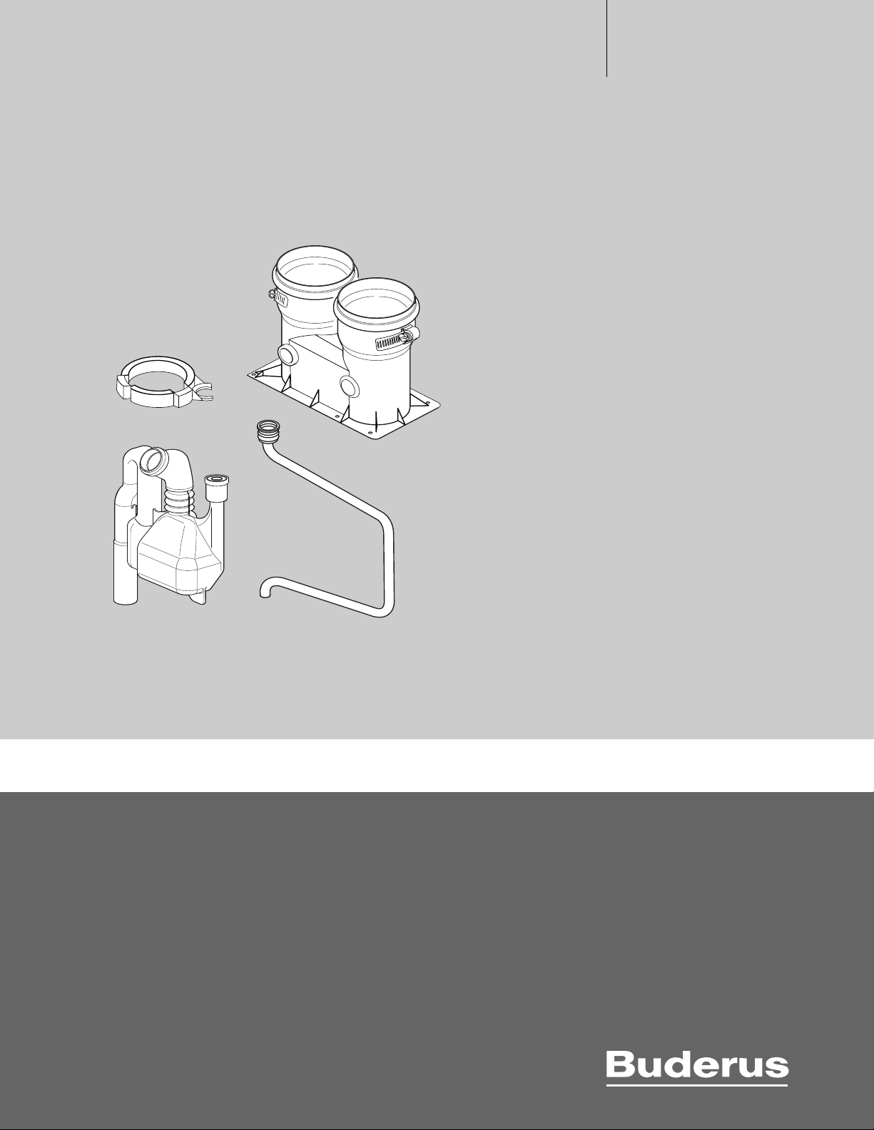
2 Scope of delivery
Fig. 1 Service kit with condensate trap, condensate bypass pipe and
flue gas adapter
This service kit contains the following parts:
[1] Flue gas adapter
[2] condensate trap
[3] condensate bypass pipe
[4] gas ring
[5] instructions
Safety instructions in this document are framed and
identified by a warning triangle which is printed on a
grey background.
Electrical hazards are identified by a lightning symbol
surrounded by a warning triangle.
Notes contain important information in cases where
there is no risk of personal injury or material losses and
are identified by the symbol shown on the left. They are
bordered by horizontal lines above and below the text.
Symbol Meaning
▶ a step in an action sequence
a reference to a related part in the document or to other
related documents
• a list entry
–a list entry (second level)
Table 1
DANGER: gas explosion.
▶ Work only on gas components when you have a
license to do so.
▶ The assembly of gas and vent connections, the initial
start-up, the electrical connections, the
maintenance and service can only be performed by a
licensed service contractor or technician.
DANGER: electrical shock.
▶ Prior to doing any work on the heating system,
disconnect all electrical powerto the appliance at the
emergency switch. It is not sufficient to shut off only
the appliance control.
6 720 801 158-002.2TD
3
1
5
2
4