Short Form Data
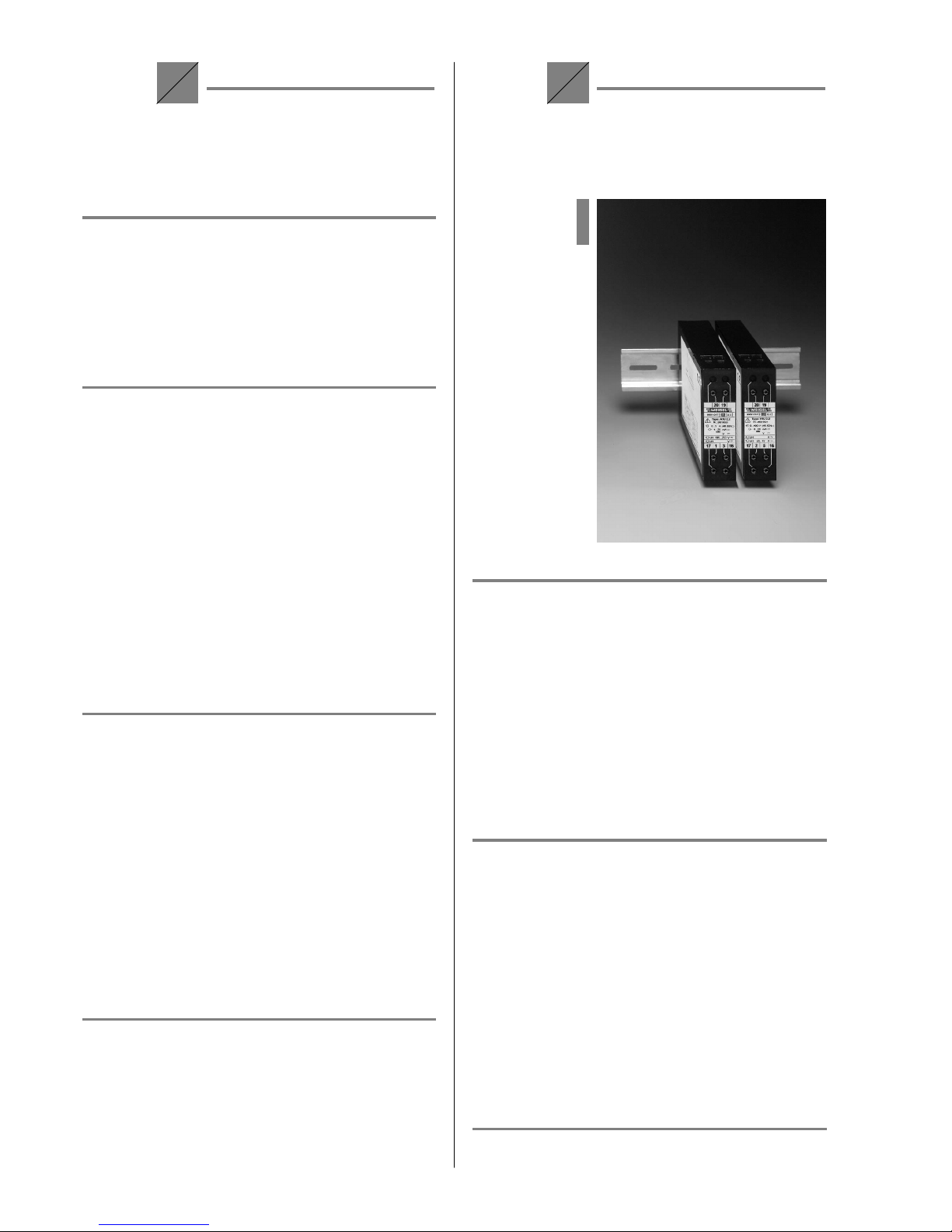
Programmable
Multi-Functional Trans-
ducer for AC Currents,
AC Voltages and Powers
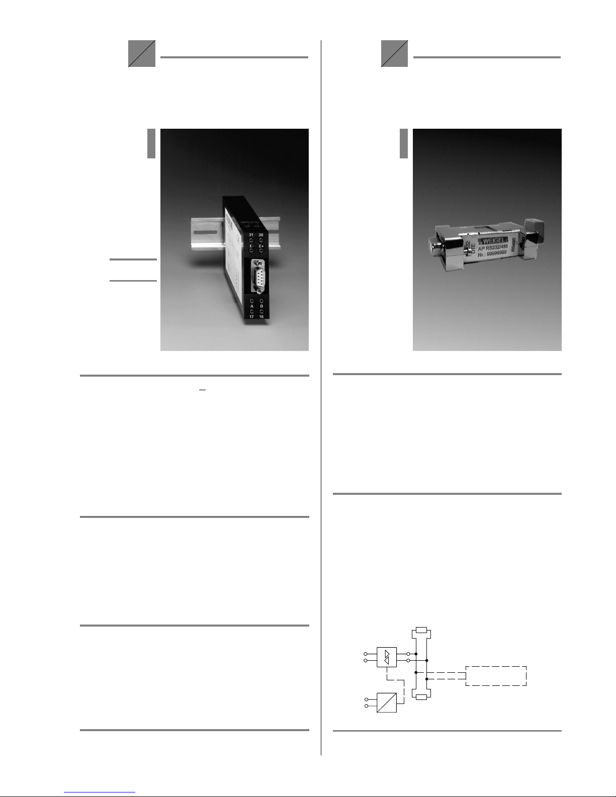
MMU 3.0
=
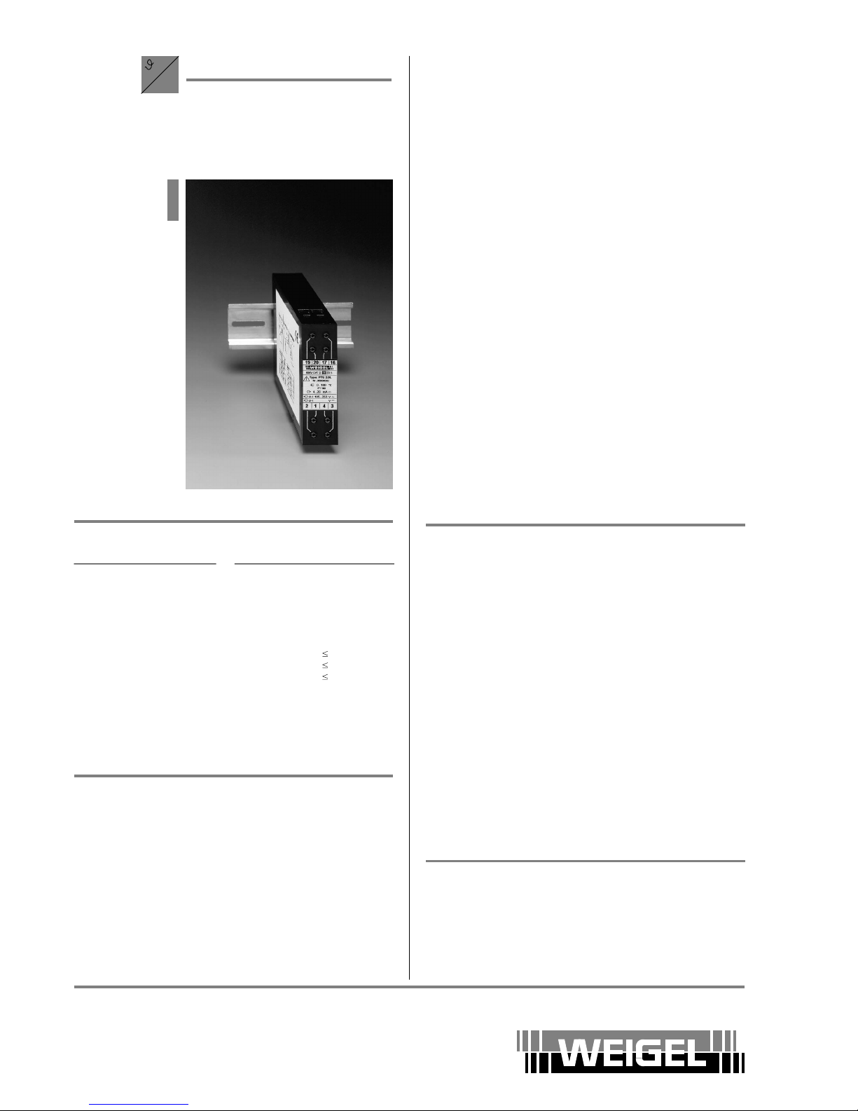
RS232
RS485
with mP
Inputs
input quantities AC current and AC voltage
in single phase or 3 phase system
voltages L1, L2, L3 (3 terminals), N (1 terminal)
600V (inter- connected) or optional N/120V (also for N/100V or N/110V)
currents I1, I2, I3 (6 terminals)
N/5 A or optional N/1.2 A (also for N/1 A)
Measuring Quantity Total L1 L2 L3
voltage (U) U U1U2U3
current (I) I I1I2I3
active power (P) P P1P2P3
reactive power (Q) Q Q1Q2Q3
apparent power (S) S S1S2S3
active factor (PF) PF PF1PF2PF3
reactive factor (QF) QF QF1QF2QF3
phase angle (PH) PH PH1PH2PH3
frequency (f) F
Depending on power system, not all these values van be measured.
10 V measuring input I P (±10 V)
Other Ratings
analog output 1 voltage & current synchronous
(2 terminals each) refer to General Data
interfaces RS 232 (SUB–D jack), RS 485 (2 terminals)
digital output contactāĆāfree via opto coupler
1, 2, or 3 additional analog outputs (galvanically isolated) and
up to 8 additional digital outputs (galvanically isolated) are optional
accuracy class 0.5 (±0.5% of end value)
auxiliary voltage wide range supply refer to General Data
dimensions basic version: 3 modules in single - phase
resp. 4 modules in three - phase systems,
optional outputs: additional 1 to 3 modules
each module WxHxL 22.5 mm x 80 mm x 115 mm
weight approx. 0.6 kg (basic version)
for detailed information refer to Data Sheet No. 055.##
prices refer to Price Sheet No. 055.##
Short Form Data
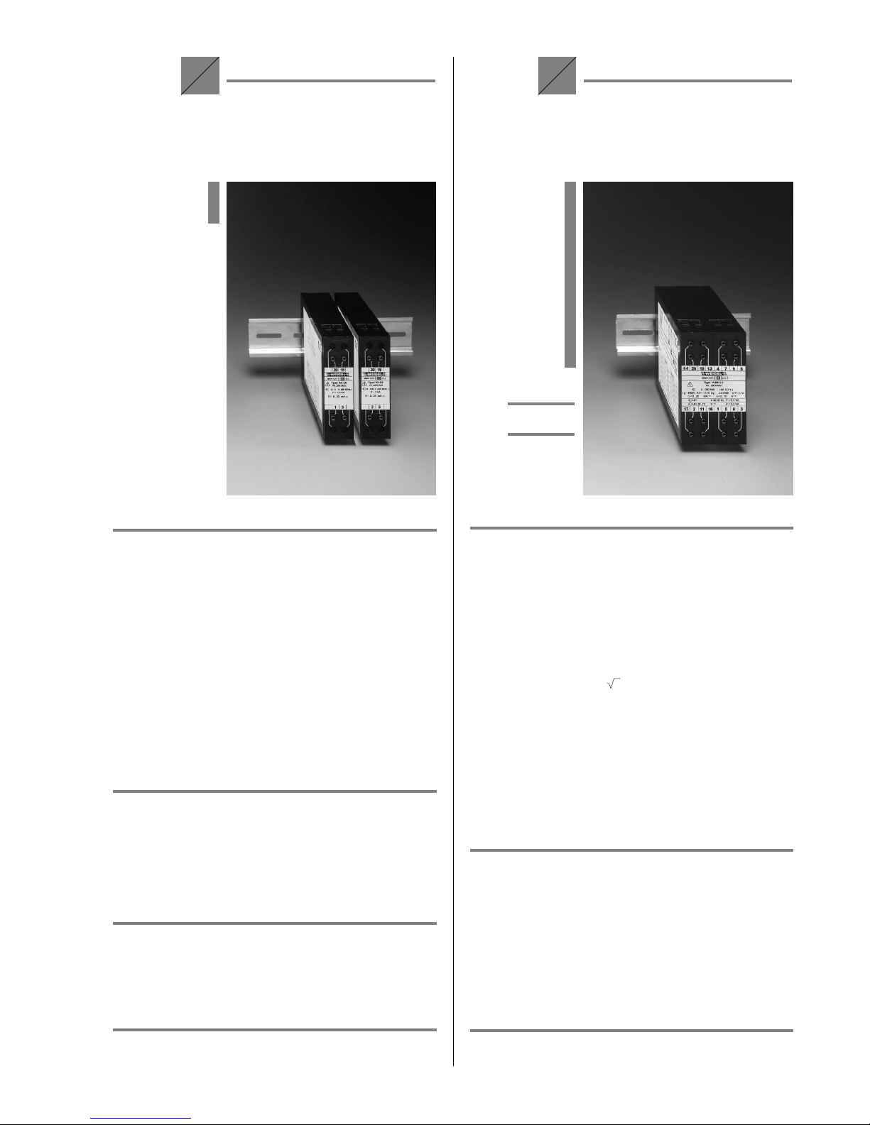
Transducers for
Active Power and
Reactive Power
DUW 2.1
DUB 2.1
VUW 2.1
VUB 2.1
=
P/Q
Inputs
input rating sinusoidal AC current and
sinusoidal AC voltage
input quantity PEactive or reactive power
type active / reactive power
3 - phase 3 - wire system unbalanced load DUW 2.1 DUB 2.1
3 - phase 4 - wire system unbalanced load VUW 2.1 VUB 2.1
measuring range 0 ... PNor –PN... 0 ... PN
PN= (0.3 ... 1.5) .PS
PS= 3.U.I
rated input voltage UEN 65 V, 100 V, 110 V, 240 V, 400 V, 415 V, 440 V,
500 V, 600 V or deviating from standard inputs
ranging from 0 ... (60 V ... UEN ... 600 V)
rated input current IEN N/1 A, N/5 A or deviating from standard inputs
ranging from 0 ... (0,5 A ... IEN ... 5 A)
modulation range 1.2 UEN and 1.2 IEN
overload limits 1.2 UEN,1.2 IEN continuously
2 UEN,10 IEN 1 s max.
frequency range 50 Hz (48 ... 52 Hz) or
162/3Hz, 60 Hz, 100 Hz, others on request
power consumption <1 mA each voltage circuit
≤0.1 VA each current circuit for IEN = 1 A
≤1.6 VA each current circuit for IEN = 5 A
Other Ratings
outputs refer to General Data
accuracy class 0.5 (±0.5% of end value)
auxiliary voltage refer to General Data
dimensions WxHxL 45 mm x 80 mm x 115 mm
weight DUW/DUB 2.1 VUW/VUB 2.1
approx. 0.29 kg approx. 0.31 kg
for detailed information refer to Data Sheet No. 051.##
prices refer to Price Sheet No. 051.##