Weil-McLain Ultra Electric Water Heater Installation and operation manual
Other Weil-McLain Boiler manuals

Weil-McLain
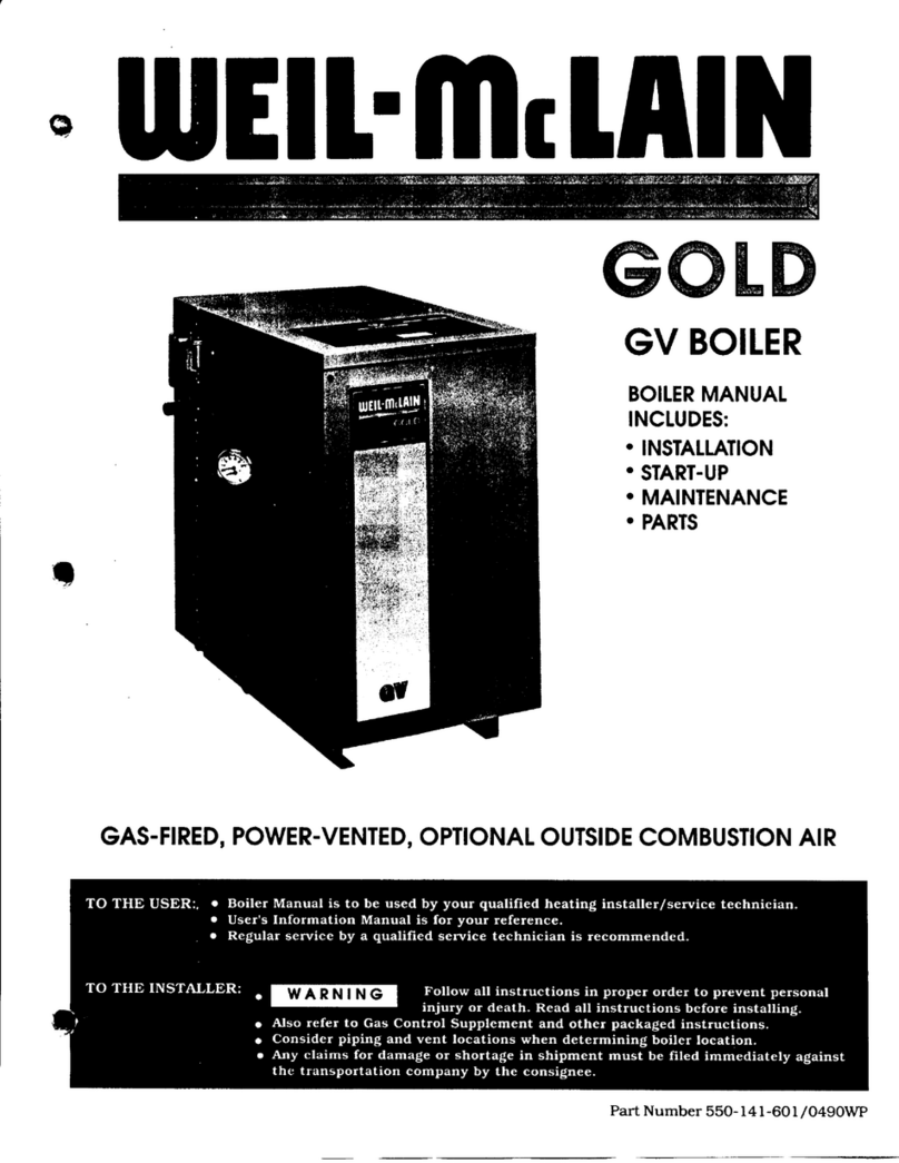
Weil-McLain GOLD CGI 550-110-710/0107 User manual

Weil-McLain
Weil-McLain PER 550-141-396/0801 User manual

Weil-McLain
Weil-McLain HE (Series 2) User manual

Weil-McLain
Weil-McLain HE II Boiler User manual

Weil-McLain
Weil-McLain ECO 70 User manual

Weil-McLain
Weil-McLain Evergreen EVG 70 User manual
Weil-McLain
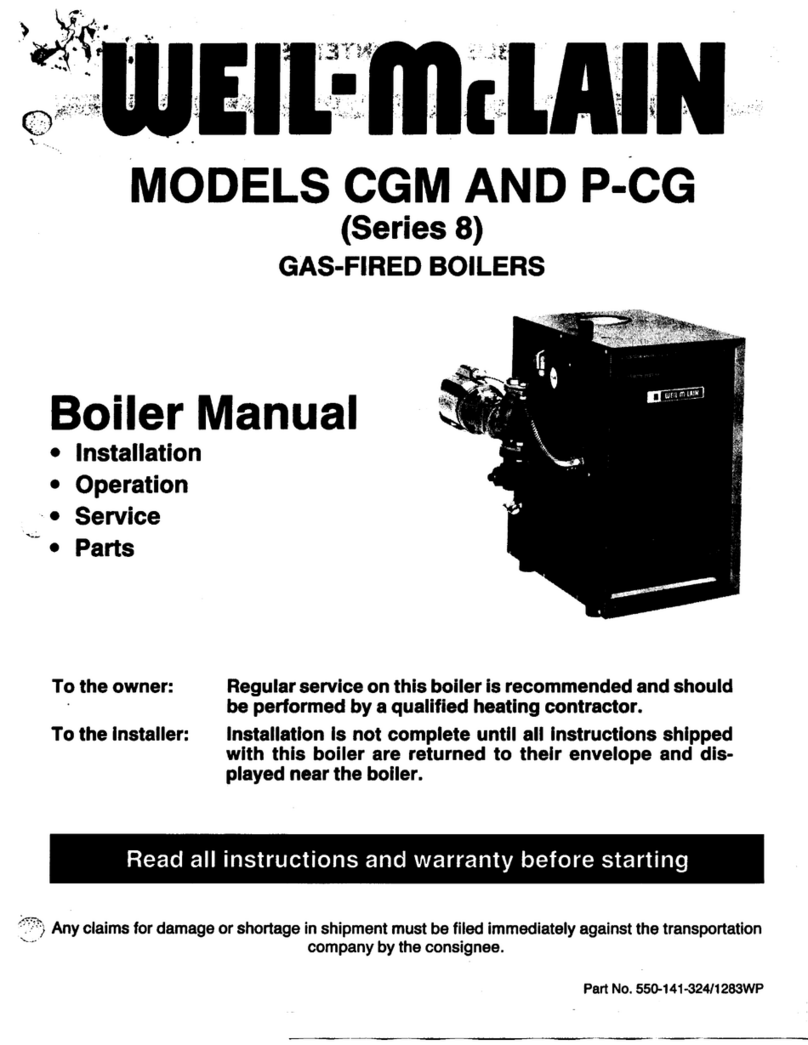
Weil-McLain CG Series 10 User manual

Weil-McLain
Weil-McLain WM97+ Aqua Logic Guide

Weil-McLain
Weil-McLain WM97-70-CT User manual

Weil-McLain
Weil-McLain Ultra Electric Water Heater User manual
Weil-McLain
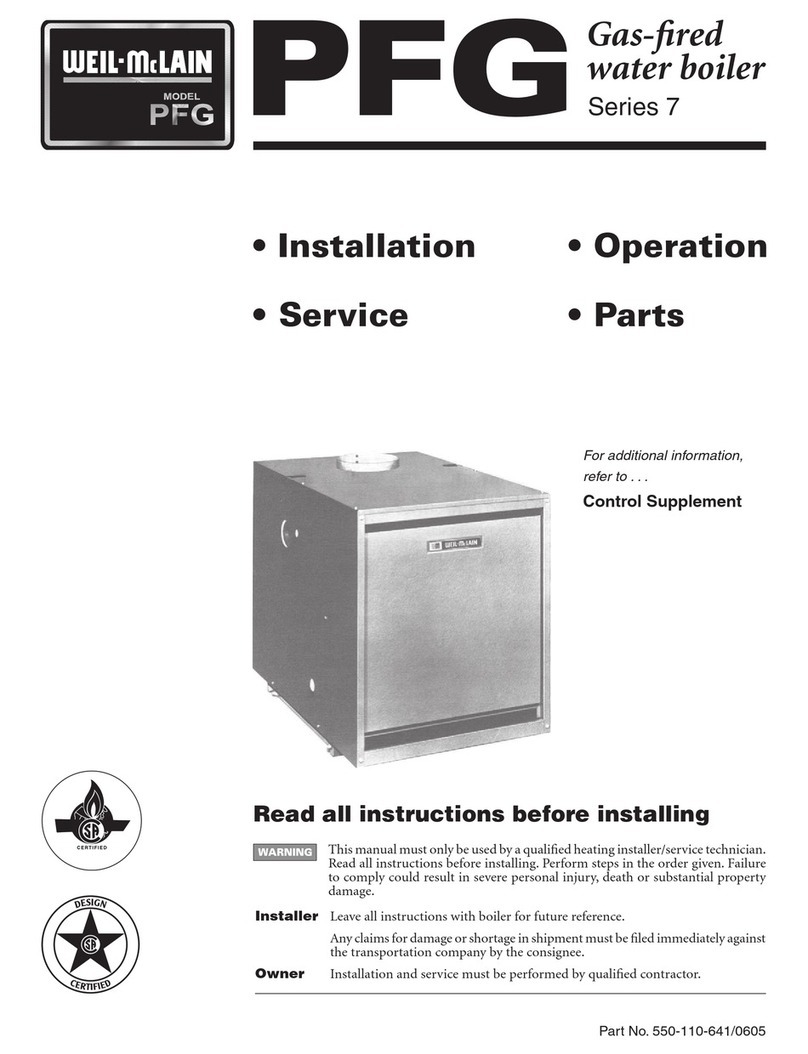
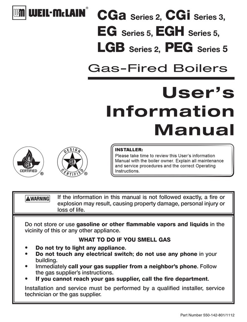
Weil-McLain PEG 5 Series Guide

Weil-McLain
Weil-McLain 550-141-829/1201 User manual
Weil-McLain
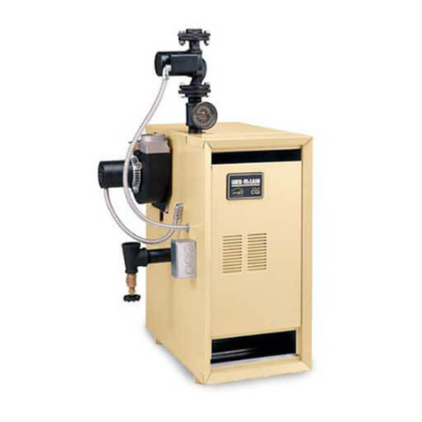
Weil-McLain GOLD CGa User manual

Weil-McLain
Weil-McLain Ultra Electric Water Heater User manual

Weil-McLain
Weil-McLain AHE Series User manual
Weil-McLain
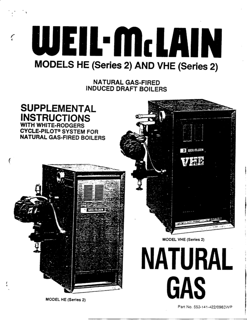
Weil-McLain VHE (Series 2) Guide

Weil-McLain
Weil-McLain Ultra Electric Water Heater Installation and operating instructions

Weil-McLain
Weil-McLain GV90+ Installation and operation manual

Weil-McLain
Weil-McLain SVF 500 User manual
Weil-McLain
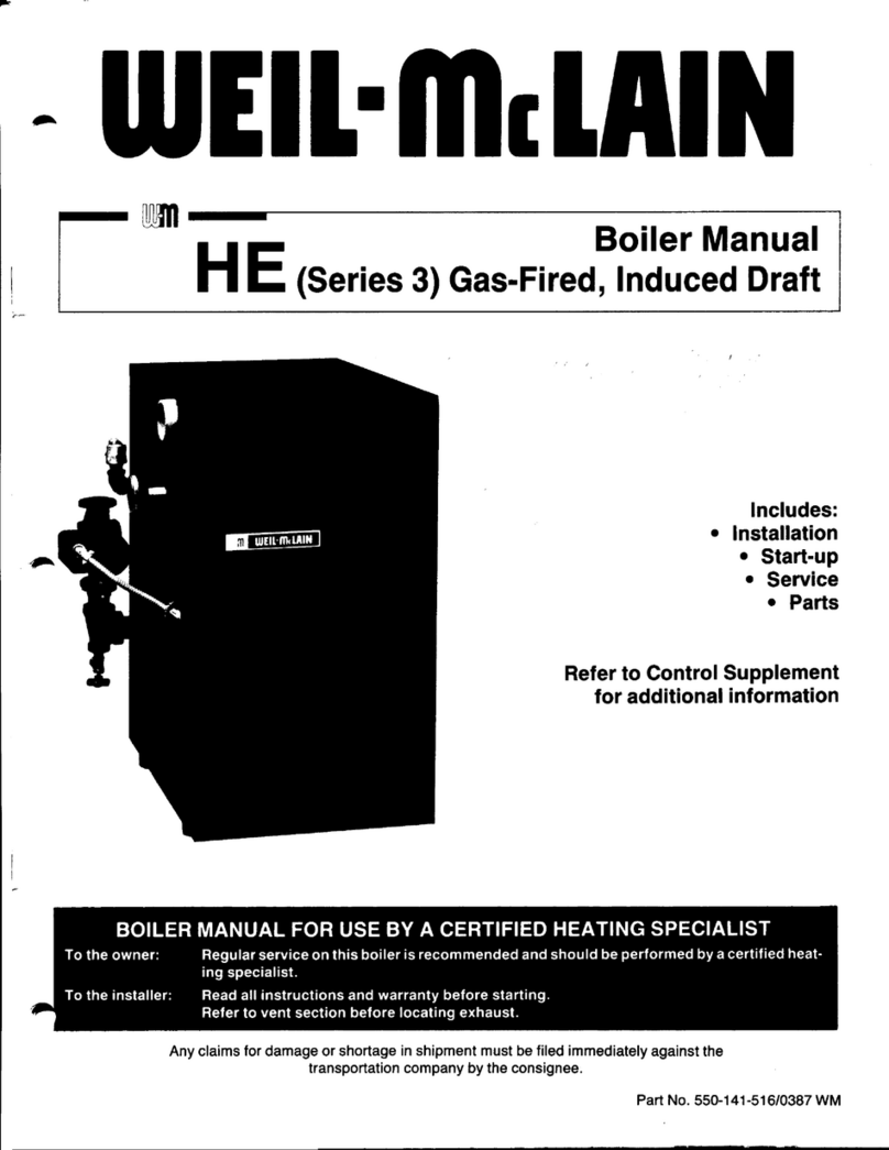
Weil-McLain HE (Series 3) User manual
Popular Boiler manuals by other brands

IDEAL
IDEAL IMAX XTRA EL 320 user guide

UTICA BOILERS
UTICA BOILERS BC3D Installation, operation & maintenance manual

Lochinvar
Lochinvar SOLUTION 260000 Installation & service manual

RBI
RBI LCD Series Installation & operation manual

Baxi
Baxi MainEco Combi 28 Installation and service manual

Unical
Unical ALKON R 24 Installation and Servicing Manual

Automatic Heating
Automatic Heating Gasogen Installation and Servicing Manual

Viessmann
Viessmann VITORADIAL 300-T Type VR3 Service instructions for contractors

Alpha
Alpha GasSaver GS-1 Installation and servicing instructions

Baxi
Baxi ROCA LAURA PLUS 28/28 Operating, cleaning and maintenance instructions for the user

Vaillant
Vaillant uniSTOR VIH SW GB 500 BES operating instructions

Kärcher
Kärcher HWE 4000 Gas manual

Radijator
Radijator BIO max 23.1 instruction manual

Granby
Granby BKC Installation, operation and maintenance manual

Brunner
Brunner BSV 20 Instructions for use

Potterton
Potterton 50e Installation and Servicing Manual

UTICA BOILERS
UTICA BOILERS TriFire Assembly instructions

ECR International
ECR International UB90-125 Installation, operation & maintenance manual
