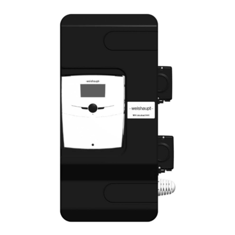
Weishaupt WHI freshaqua 44 User manual

Mounting and operating instructions
Fresh w
ater station WHI freshaqua 44
Fresh water station WHI freshaqua 55
83514402 ▪ 1/2017-
08

EU conformity certification
Language 02
Product description Fresh water station
Type WHI freshaqua …
Manufacturer Max Weishaupt GmbH
Address Max-Weishaupt-Straße 14, DE-88475 Schwendi
The sole responsibility for issuing this conformity declaration lies with the manufacturer.
The content of the statement described above complies with the relevant harmonisation legislation of the European
Union:
EMC 2014/30/EU
LVD 2014/35/EU
Standard applied: EN 60335-1
Schwendi, 17/08/2016
Signed for and on behalf of:
MAX WEISHAUPT GMBH
ppa.
Dr. Schloen
Manager research and Development
ppa.
Denkinger
Manager Production and Quality Management

Installation and operating instructions
Fresh w
ater station WHI freshaqua 44; Fresh water station WHI freshaqua 55
83514402
▪ 1/2017-08 ▪ Ext. PAW 3-36
1
Information for the user............................................................................4
1.1
User guidance.......................................................................................................... 4
1.1.1
Symbols.................................................................................................................... 4
1.1.2
Target group............................................................................................................. 4
1.2
Warranty and liability............................................................................................... 4
2
Safety ..................................................................................................5
2.1
Designated use........................................................................................................ 5
2.2
Safety instructions................................................................................................... 5
2.3
Safety measures...................................................................................................... 6
2.4
Electrical connection............................................................................................... 6
2.5
Structural modifications.......................................................................................... 6
2.6
Disposal.................................................................................................................... 6
3
Product description.................................................................................7
3.1
Function.................................................................................................................... 8
3.2
Serial number........................................................................................................... 8
3.3
Technical Data......................................................................................................... 9
3.4
Technical Data Pumps.........................................................................................11
3.5
PWM input signal (solar profile)..........................................................................11
3.6
Hydraulic performance data.................................................................................12
4
Dimensioning and Planning....................................................................13
4.1
Dimensioning the storage....................................................................................15
4.2
Circulation mode....................................................................................................16
5
Installation ..........................................................................................17
5.1
Assembly................................................................................................................18
5.2
Connection.............................................................................................................19
5.3
Controller connection............................................................................................20
6
Operation ...........................................................................................20
7
Commissioning....................................................................................21
7.1
Filling the primary circuit.......................................................................................22
7.2
Commissioning the controller..............................................................................23
7.3
Maximum tapped flow rate...................................................................................24
7.4
Setting the temperature........................................................................................26
8
Maintenance .......................................................................................28
9
Spare parts.........................................................................................29
9.1
Spare parts list WHI freshaqua 44......................................................................29
9.2
Spare parts list WHI freshaqua 55......................................................................31
10
Accessories ........................................................................................33
10.1
Withdrawal valve...................................................................................................33
10.2
Circulation set........................................................................................................33
11
Commissioning log...............................................................................34
12
Notes.................................................................................................35

Installation and operating instructions
Fresh w
ater station WHI freshaqua 44; Fresh water station WHI freshaqua 55
1 Information for the user
83514402
▪ 1/2017-08 ▪ Ext. PAW 4-36
1
Information for the user
These installation and operation instructions form partof the device and mustbe
stored at the place of use.
Carefully read these instructions before installation and commissioning.
1.1
User guidance
1.1.1
Symbols
DANGER
Immediate danger ofhigh risk.
Non-observance will resultin serious injuries or death.
WARNING
Danger of medium risk.
Non-observance may resultin environmental damage,
serious injuries or death.
CAUTION
Danger of low risk.
Non-observance may resultin property damage or slight
to moderate injuries.
NOTICE
Importantinformation.
1.1.2
Target group
This installation and operation manual is addressed to operatorsand qualified skilled
personnel.It must be observed by
anyone working on the machine.
Work on the machine may onlybe performed bypersons that have received the required
training or instruction.
Persons with restricted physical, sensory or mental abilities may work on the machine if
supervised or instructed b
y an authorized person.
Children may notplay with the machine.
1.2
Warranty and liability
Warranty and lilability claims for personal and material damage are void ifthey are due
to one or several of the following causes:
Use of the machine contrary to its designated use,
Non
-observance ofthe installation and operation instructions,
Operation of the machine with non
-operational safety or protective devices,
Continued use despite the presence of a defect,
Improper assembly,commissioning, operation an
d maintenance ofthe machine,
Unauthorised modification of the machine,
Installation of additional components thatwere not tested together with the machine,
Repairs carried out incorrectly,
Failure to use Weishauptoriginal parts
,
Defects in the supply
lines,
Force majeure.

Installation and operating instructions
Fresh w
ater station WHI freshaqua 44; Fresh water station WHI freshaqua 55
2 S a fety
83514402
▪ 1/2017-08 ▪ Ext. PAW 5-36
2
Safety
2.1
Designated use
The fresh water station must only be installed in heating systems between the buffer
tank and the
domestic water circuit. Due to its construction, it must only be installed and
operated in a vertical position.The technical limitvalues specified in this
instruction
mustbe considered.
Use only original accessories in connection with the fresh water station.
Using the station contrary to its designated use will invalidate all liability claims.
The wrapping materials are made ofrecyclable materialsthat c
an be recycled by
standard recycling operations.
2.2
Safety instructions
The following mustbe observed during installation and commissioning:
•Relevantlocal and national regulations
•
Accidentprevention regulations ofthe employers' liability insurance association
•Instructions and safety instructions mentioned in these instructions
WARNING
Risk of scalding from hot water!
Due to the third party circulation,up to 90 °C hot water may run
out at the tapping pointin the primarycircuit.
No external pump may be installed between the fresh
water station and the buffer tank.
The fresh water station must not be connected to a
heating circuitdistributor.
CAUTION
Risk of burns!
The valves and fittings and the pumps can become heated up
to more than 95 °C during operation.
The insulation mustremain closed during operation.

Installation and operating instructions
Fresh w
ater station WHI freshaqua 44; Fresh water station WHI freshaqua 55
2 S a fety
83514402
▪ 1/2017-08 ▪ Ext. PAW 6-36
NOTICE
Material damage due to mineral oils!
Mineral oil products cause permanentdamage in the material,
resulting in its sealing characteristicsgetting lost.
We cannot be held liable for damage caused by seals thus
damaged, nor will we offer a replacement under warranty.
It is imperative to preventthe EPDM from making contact
with substances containing mineral oils.
Use a silicone- or polyalkylene-based lubricantfree of
mineral oilsuch as UnisilikonL250Land SynthesoGlep 1
from Klüber or a silicone spray.
NOTICE
Malfunctions!
The fresh water station must be integrated into the
potential equalisation of the electrical installation.
If this is not ensured by the connected pipework then
establish a correct potential equalisation connection
to the main potential connection.
2.3
Safety measures
Immediately eliminate safety
-relevantdefects and replace safety-relevantcomponents
when they have reached the end of their service life due to their construction.
2.4
Electrical connection
When performing any work on live parts:
Observe the accidentprevention regulations BGV A3 and local regulations,
u
se tools according to EN 60900.
2.5
Structural modifications
Conversion measures are only allowed after prior approval in writing by the
Max WeishauptGmbH.
Additional components may onlybe installed if they were not tested together
with the machine.
Use only Weishauptoriginal parts.
2.6
Disposal
Dispose of the materialsused properly and in an environmentally compatible manner.
In doing so, observe
local regulations.

Installation and operating instructions
Fresh w
ater station WHI freshaqua 44; Fresh water station WHI freshaqua 55
3 Product description
83514402
▪ 1/2017-08 ▪ Ext. PAW 7-36
3
Product description
The fresh water station is a pre
-assembled fittings group tested for leaksfor transferring
heat between the buffer tank and the
domestic water circuit.
It containsa preset controllerand importantvalves and fittings for operating the system:
•Ball valves in the primary circuit
•Piston valves in the secondary circuit
•Safety valve in the secondary circuit
•Pre-assembled controller
•Temperature sensoron the cold watersupply
•Temperature sensors on the heating supply
•Temperature sensoron the warm domestic water outlet
•Flow meter on the warm domestic water outlet
•Fill and drain valve for draining the heat exchanger and the pump
•
Vent plug for venting the heat exchanger
Connections
1
Primary side: return to buffer tank
2
Secondary side:cold water inlet
3
Secondary side:hot water outlet
4
Primary side: supply from buffer tank
Equipment
A
Ball valve with check valve
B
Primary pump
C
Piston valve with drain valve
D
Piston valve with drain valve and temperature sensor
E
Valve for filling and draining and temperature sensor
F
FlowSonic flow meter
G
Plate heatexchanger
H
Vent valve (primary circuit)
I
Safety valve 10 bars and temperature sensor
(Only for protection of the station. Does not replace
the safety valve that mustbe installed on-site.)
J
Ball valve with check valve

Installation and operating instructions
Fresh w
ater station WHI freshaqua 44; Fresh water station WHI freshaqua 55
3 Product description
83514402
▪ 1/2017-08 ▪ Ext. PAW 8-36
3.1
Function
The fresh water stations WHI freshaqua are used for the comfortable and hygienic
heating of
domestic water according to the continuous flow heater principle. Other than
in conventional
domestic water storage tanks, foodstuff water is not used for energy
storage and stored as hot water for hoursor days. It is only heated when required using
a
high-performance plate heatexchanger.The energyfor heating the domestic water
comesfrom a buffer tank that can be heated by different systems
- using solar systems
as well as solid fuel boilers,oil / gas boilers,heatpumps or other systems.
The WHI freshaqua mo
dules are well suited for use in combination with a thermal solar
system. The very good cooling of the heating water in the highly effective plate heat
exchangers leads to an increased efficiency of the solar circuit as the average tempera-
ture of the solar
circuitcan be reduced due to the cold return.
In event of great tapping differences,the WHI freshaqua fresh water stations always
have to guarantee a constant outlet temperature atthe hot water tap.
The speed of the highlyefficient EC pumps of the la
test generation is controlled by
a high
-performance closed-loop control always allowing the heating flow rate to be
optimally setto the current tap capacity.
The closed
-loop control receives the necessary information for adjusting the system
from a flo
w rate sensor and extremely fast temperature sensorsthat detect the smallest
temperature deviations immediately.
The WHI freshaqua units can be optionally equipped with a circulation kit
with highly efficientEC circulation pump for internal retrofittin
g. The closed-loop
control can operate the pump in different circulation modes;always adapted to
the current system and requirements ofthe customer.
During commissioning,the circulation return temperature can be set individually on the
circulation sys
tem so that the recordable and traceable DVGW (551)requirements for
a maximum cooling of the circulation by 5 K can be fulfilled.
Thus, the WHI freshaqua therefore offer perfect comfort, optimum hygiene and a
future-orientated energy saving operation.
3.2
Serial number
The serial number on the type plate clearly identifies each product. The serial number is
necessary for the Weishaupt after
-sales service. In case of a complaint,please send us
the serial number ofthe product concerned and the completed commissioning rep
ort
(see page
34). The serial number is placed in the lower right cornerof the supportsheet
of the station.
Serial number:

Installation and operating instructions
Fresh w
ater station WHI freshaqua 44; Fresh water station WHI freshaqua 55
3 Product description
83514402
▪ 1/2017-08 ▪ Ext. PAW 9-36
3.3
Technical Data
Dimensions
WHI freshaqua 44
WHI freshaqua 55
Height(with insulation)
795 mm
Width (with insulation)
602 mm
Depth (with insulation)
298 mm
Centre distance, top
120 mm
Centre distance, bottom
100 mm
Primary pipe connection
(storage tank circuit)
1½" male thread, flat sealing 2" male thread, flat sealing
Secondary pipe connection
(WHI freshaqua)
1" male thread, flat sealing 1¼" male thread, flat sealing
Safety valve outlet
G ¾" female thread
Operating data
Max. admissible pressure
primary: 6 bars,
secondary: 10 bars
Min. flow rate
1 l/min
Operating temperature
2 – 95°C
Max. power Qmax 153 kW at flowpr im. 75 °C /
DHWsec. 60 °C / DCWsec. 10 °C
192 kW at flowpri m. 75 °C /
DHWsec. 60 °C / DCWsec. 10 °C
Flow rate at Qmax primary: 2500 l/h,
secondary: 44 l/min
primary: 3000 l/h,
secondary: 55 l/min
Operating temperature sensors
-25 °C to +120 °C
Equipment
Safety valve
secondary: 10 bars, suitable for domestic water
Primary pump High-efficiency pump
with PWM control, 3-70 W
High-efficiency pump
with PWM control, 3-140 W
Heat exchanger
40 plates
60 plates
Flow rate sensor
FlowSonic, measuring range: 1-80 l/min
Temperature sensors primary: 1 x Pt1000, rapid;
secondary: 2 x Pt1000, rapid
Checkvalve (in the ball valve)
primary: 2 x 200 mm wc
primary: 2 x 800 mm wc

Installation and operating instructions
Fresh w
ater station WHI freshaqua 44; Fresh water station WHI freshaqua 55
3 Product description
83514402
▪ 1/2017-08 ▪ Ext. PAW 10-36
Material
WHI freshaqua 44
WHI freshaqua 55
Valves and fittings
Brass
Seals: o-ring
Klingersil / EPDM
Flat sealing
AFM 34, free of asbestos
check valve
Brass
Pipes
1.4401 (AISI 316)
Insulation
EPP,
λ
= 0.038 W/(m K), fire class B2
Heatexchanger with copper soldering
(WHI freshaqua 44 #1 and 55 #3)
Plates + connecting pieces: 1.4401 (AISI 316)
Solder: 99.99% pure copper
Heat exchanger with nickel soldering
(WHI freshaqua 44 #2 and 55 #4)
Plates + connecting pieces: 1.4401 (AISI 316)
Solder: 99.99% nickel
Admissible medium
(WHI freshaqua 44 #1 and 55 #3)
primary: heating water according to VDI 2035 / Ö-Norm H 5195-1
secondary: domestic water with a max. chloride content: ≤ 80 ppm
Admissible medium
(WHI freshaqua 44 #2 and 55 #4)
primary: heating water according to VDI 2035 / Ö-Norm H 5195-1
secondary: domestic water with a max. chloride content: ≤ 300 ppm
Certification SVGW (1308-6180)
ACS (15 ACC NY 015)

Installation and operating instructions
Fresh w
ater station WHI freshaqua 44; Fresh water station WHI freshaqua 55
3 Product description
83514402
▪ 1/2017-08 ▪ Ext. PAW 11-36
3.4
Technical Data Pumps
Grundfos UPM2 25-75 LowFlow
Grundfos UPML 25-105
Length
180 mm
Connections
1½" male thread
Protection class
IP 44
IPX2D
Max. pressure
1.0 MPa (= 10 bars)
Max. temperature
95 °C TF 95
I ( 1 /1)
0.04-0.52 A
0.06-1.16 A
P1
3-70 W
6-140 W
Use in
WHI freshaqua 44
Prim
WHI freshaqua 55
Prim
Prim = Primary side (accumulator circuit)
3.5
PWM input signal (solar profile)
PWM input signal
[%]
P u mp s tatus
< 6 Standby
6-8 Hysteresis
9-15 Min.
speed
16-90 Linear increase in
speed from rpm
min.to rpm max.
91-100 Max.
speed
Speed
PWM input signal [%]
Min.
Stop
Max
.

Installation and operating instructions
Fresh w
ater station WHI freshaqua 44; Fresh water station WHI freshaqua 55
3 Product description
83514402
▪ 1/2017-08 ▪ Ext. PAW 12-36
3.6
Hydraulic performance data
WHI freshaqua 44
WHI freshaqua 55
Residual feed pressure or pressure drop [mbars]
Flow rate [l/h]
Heating UPM2 25-75 L o w Fl ow
Circulation UPM215-75 CIL
Pressure drop DW side
Residual feed pressure or pressure drop [mbars]
Flow rate [l/h]
Pressure drop DW side
Circulation UPM215-75 CIL
Heating UPML 25-105

Installation and operating instructions
Fresh w
ater station WHI freshaqua 44; Fresh water station WHI freshaqua 55
4 Dimensioning and Planning
83514402
▪ 1/2017-08 ▪ Ext. PAW 13-36
4
Dimensioning and Planning
The WHI freshaqua is a fresh water station that heats the
domestic water according to
the continuous flow heater principle.
The system must fulfil certain requirements for the trouble
-
free function of the fresh water
station. Take a little time
for the planning before the assembly.
Due
to their construction, the WHI freshaqua
modules reduce the precipitation ofscale in
the heat exchanger. For systems with a high total domestic water hardness and/or high
temperatures,a water treatmentis recommended,in order to preventscale formation.
WARNING
Risk of scalding from hot water!
Due to the third party circulation,up to 90 °C hot water may run
out at the tapping pointin the primarycircuit.
No external pump may be installed between the fresh
water station and the buffer tank.
The fresh water station must not be connected to a
heating circuitdistributor.
The WHI freshaqua stations in the following table differ in
the soldering material used for
the plate heat exchangers.
The choice of the heat exchanger depends on the requirements ofthe installation
location.Depending on the chemical composition ofthe water on the installation location,
an appropriate plate heatexchanger mustbe chosen.
Please observe the following table:
Heat exchanger
with copper soldering
Heat exchanger
with nickel soldering
Maximum chloride content
in the potable water ≤ 80 ppm ≤ 300 ppm
pH value 7.0 - 9.0 No limitation
Conductivity
≤ 500 μS/cm
No limitation
Zinc-galvanised piping Unsuitable Suitable
Maximum pressure at95 °C
17 bars
12 bars
Plate material
1.4401 (AISI 316)
Overview of the WHI freshaqua stations and the integrated heat exchangers:
Fresh water station
-w- Part number
Soldering material
of the heat exchanger
WHI freshaqua 44 #1
40900015032
Copper
WHI freshaqua 44 #2
40900019032
Nickel
WHI freshaqua 55 #3 40900019082 Copper
WHI freshaqua 55 #4 40900019092 Nickel

Installation and operating instructions
Fresh w
ater station WHI freshaqua 44; Fresh water station WHI freshaqua 55
4 Dimensioning and Planning
83514402
▪ 1/2017-08 ▪ Ext. PAW 14-36
Assembly example
Fresh water station with optional circulation kit(item no. 40900015462)
and
with optional
return distribution
In order to guarantee optimum closed
-loop control,where possible no hydraulic
pressure
drop
should occur on the primary side (e.g., from the installation of a mud strainer, dirt
trap or mix
ing valve).

Installation and operating instructions
Fresh w
ater station WHI freshaqua 44; Fresh water station WHI freshaqua 55
4 Dimensioning and Planning
83514402
▪ 1/2017-08 ▪ Ext. PAW 15-36
4.1
Dimensioning the storage
Using the
following table,you can calculate the approximate required volume ofthe
buffer tank.
Temperature in the
buffer tank
Hot water temperature set
on the controller
Required storage volume
per litre hot water
50 °C 45 °C 1.3 litres
45 °C
0.8 litres
60 °C
50 °C
1.0 litres
55 °C
1.4 litres
45 °C 0.7 litres
70 °C
50 °C
0.8 litres
55 °C
0.9 litres
45 °C 0.5 litres
80 °C
50 °C
0.6 litres
55 °C
0.7 litres
Calculation example for dimensioning the buffer tank:
Buffer tank temperature:60
°C
Required tapped flow rate at the tap: 20 l/min
DHW
temperature seton the controller:45 °C
How large does the tank have to be if tapping i
s carried out for 20 minutes without
reheating?
20 l/min x 20 min = 400 l
400 l x 0.8 = 320 l
The heated part of the buffer tank musthave a volume of 320 litres.

Installation and operating instructions
Fresh w
ater station WHI freshaqua 44; Fresh water station WHI freshaqua 55
4 Dimensioning and Planning
83514402
▪ 1/2017-08 ▪ Ext. PAW 16-36
4.2
Circulation mode
The fresh w
ater stations WHI freshaqua 44 as well as WHI freshaqua 55 can be
subsequentlyequipped with a circulation kit(item no. 40900015462) for internal
retrofitting as an option.
Three possible operating modes are stored in the controllerfor operating the circulation
pump (see also operating instructions of controller,menu
"Func" / "F02"):
•
Pulse-controlled operation (requirement dependent / demand):
The circulation pump is started by briefly opening a hot water tap point
(tapping pulse:~2 seconds). The circulation pump then onlyrunsfor a few minutes
(can be set).
•
Time-dependent operation:
The operation of the circulation pump can be set on a week clock within a freely
definable time period.With this operating mode,the circulation is started at the beginning
of the set time period.The circulation is
switched off after the set time period has
elapsed.
•
Temperature-dependent operation:
With this operating mode,the circulation is only started if the minimum temperature that
can be set on the circulation temperature sensoris not exceeded within the operating
period.The circulation is switched off after reaching the nominal temperature t
hatcan
be set or after the set time period has elapsed.
The operating modes can be combined as desired,e.g., time and temperature
-
dependentoperation.In doing so, the circulation is only active if the temperature
on the circulation temperature
sensor has exceeded and the time window is active.
Outside the time window,the circulation pump can also be activated via a tapping mode
when the additional pulse controlled operation is activated.
NOTICE
Damage to property!
In its deliverystate, the circulation is not yet active
(see operating instructions ofthe controller,menu "Func"/ "F02"
to "OFF").
As soon as the circulation line has been installed,the operating
mode mustbe selected and pre-set under all circumstances.
The revolution speed of the circulation pump mustbe specified
via the PWM signal (factory setting: 40%).

Installation and operating instructions
Fresh w
ater station WHI freshaqua 44; Fresh water station WHI freshaqua 55
5 Installation
83514402
▪ 1/2017-08 ▪ Ext. PAW 17-36
5
Installation
The domestic water connection mustbe carried out according to the relevantstandards
(e.g., DIN 1988)!
NOTICE
Material damage!
The safety valve integrated into the station does not
replace the safety equipmentofthe domestic water
connection according to DIN 1988.
The safety valve merelyprotects the station from excess
pressures when maintenance is required.
The discharge lines of the pressure reliefvalves must
be conducted into appropriate collecting containers.
The corresponding norms mustbe respected.
Fresh
water
station
Service water fitting
Drain valve
Safety valve
Non-return valve
Pressure-reducing valve, if necessary
Test valve
Shut-off valve
Hot
water
Cold
water

Installation and operating instructions
Fresh w
ater station WHI freshaqua 44; Fresh water station WHI freshaqua 55
5 Installation
83514402
▪ 1/2017-08 ▪ Ext. PAW 18-36
5.1
Assembly
WARNING
Risk to life and limb due to electric shock!
Prior to performing electrical workon the controller,
de-energise the system.
For more information,see enclosed installation and
operation instructions of the station controller.
Connectthe fresh water station to the power supply
system (230 V, 50 Hz) only after completing all
installation tasks, filling and flushing.This avoids
an unintentional startof the motors.
NOTICE
Material damage!
In order to avoid damaging the system, the installation
site must be dry, structurally safe, frost-free and
protected againstultravioletradiation.
Furthermore,access to the closed-loop control and
safety equipmentmustbe guaranteed atall times
during operation!
If tapping points are connected to the same network
as the fresh water station, in which pressure surges are
possible (e.g., flushing valves,washing machinesor
dishwashers),we recommend the installation ofwater
hammer dampersnear the device causing the
pressure surges.
1. Determine the installation location ofthe fresh water station near to
the buffer tank. With long connecting lines,the transfer capacity is
reduced due to higher pressure drops.
2. For assembly,a drilling pattern can be used as mounting aid.
This is available on the station.
3. Transfer the dimensions for the drill holes onto the wall.
4. Drill the holes and insert appropriate wall plugs.Make sure that the
ground has sufficient load-carrying capacity.
5. Screw the screws into the plug until it protrudesabout40 mm from
the wall.
6. Remove the station from the packaging.
7. Pull off the front shell.
8. Hang the fresh water station on the screws.
Tighten the screws so that the insulation on the sides rest against
the wall.

Installation and operating instructions
Fresh w
ater station WHI freshaqua 44; Fresh water station WHI freshaqua 55
5 Installation
83514402
▪ 1/2017-08 ▪ Ext. PAW 19-36
5.2
Connection
Pipe the fresh water station
with the system according to the diagram below.
Pipe gap from the wall
(primary) = 95 mm
Pipe gap from the wall
(secondary) = 167 mm
1
Primary side: return to buffer tank
Connection WHI freshaqua 44: 1½" male thread,flat sealing
Connection WHI freshaqua 55: 2" male thread,flat sealing
Piping:
WHI freshaqua 44:min. DN 25, 28 x 1.5 mm,
WHI freshaqua 55:min. DN 32, 35 x 1.5 mm
2
Secondary side: cold water inlet
Connection WHI freshaqua 44: 1" male thread,flat sealing
Connection WHI freshaqua 55: 1¼" male thread,flat sealing
3
Secondary side: hot water outlet
Connection WHI freshaqua 44: 1" male thread,flat sealing
Connection WHI freshaqua 55: 1¼" male thread,flat sealing
4
Primary side: supply from buffer tank
Connection WHI freshaqua 44: 1½" male thread,flat sealing
Connection WHI freshaqua 55: 2" male thread,flat sealing
Piping:
WHI freshaqua 44:min. DN 25, 28 x 1.5 mm,
WHI freshaqua 55:min. DN 32, 35 x 1.5 mm

Installation and operating instructions
Fresh w
ater station WHI freshaqua 44; Fresh water station WHI freshaqua 55
6 Operation
83514402
▪ 1/2017-08 ▪ Ext. PAW 20-36
5.3
Controller connection
WARNING
Risk to life and limb due to electric shock!
Prior to performing electrical workon the controller,
de-energise the system.
For more information,see enclosed installation and
operation instructions of the station controller.
Connectthe fresh water station to the power supply
system (230 V, 50 Hz) only after completing all
installation tasks, filling and flushing.
This avoids an unintentional startof the motors.
The plug-in pump lines are permanently supplied with a
mains voltage of 230 V and cannotbe switched off via
the controller.
The fresh water station is pre
-wired in the factory. When using the circulation pump,
its connection can be obtained from the enclosed assembly instructions.
6
Operation
A detailed description ofthe operation ofthe controllercan be found in the enclosed
controller manual.
This manual suits for next models
1
Table of contents
Other Weishaupt Water System manuals
Popular Water System manuals by other brands

deconta
deconta C110 L 110V instruction manual

Bluevua
Bluevua RO500X6 instruction manual

Tsunami
Tsunami TSUNAMI-500 Operating and maintenance

oventrop
oventrop OVSOL System 5 manual

Everpure
Everpure Coldrink 1-MC2 System EC210 Specification sheet

Everpure
Everpure ScaleKleen EV9655-00 Installation and operation guide