Weishaupt WHI circuload 9 1 User manual

Mounting and operating instructions
Circulation station WHI circuload 9 #1
Circulation station WHI circuload 9 #2
83288702 ▪ 1/2014-
02


Assembly and installation instructions
Circulation station WHI circuload 9 #1; Circulation station WHI circuload 9 #2
83288702
▪ 1/2014-02 ▪ Ext. PAW 3-24
1
Information for the user ..................................................................................... 4
1.1
User guidance...............................................................................................4
1.1.1
Symbols........................................................................................................4
1.1.2
Target group .................................................................................................4
1.2
Warranty and liability.....................................................................................4
2
Safety ............................................................................................................... 5
2.1
Designated use.............................................................................................5
2.2
Safety instructions ........................................................................................5
2.3
Safety measures...........................................................................................6
2.4
Electrical connection.....................................................................................6
2.5
Structural modifications.................................................................................6
2.6
Disposal........................................................................................................6
3
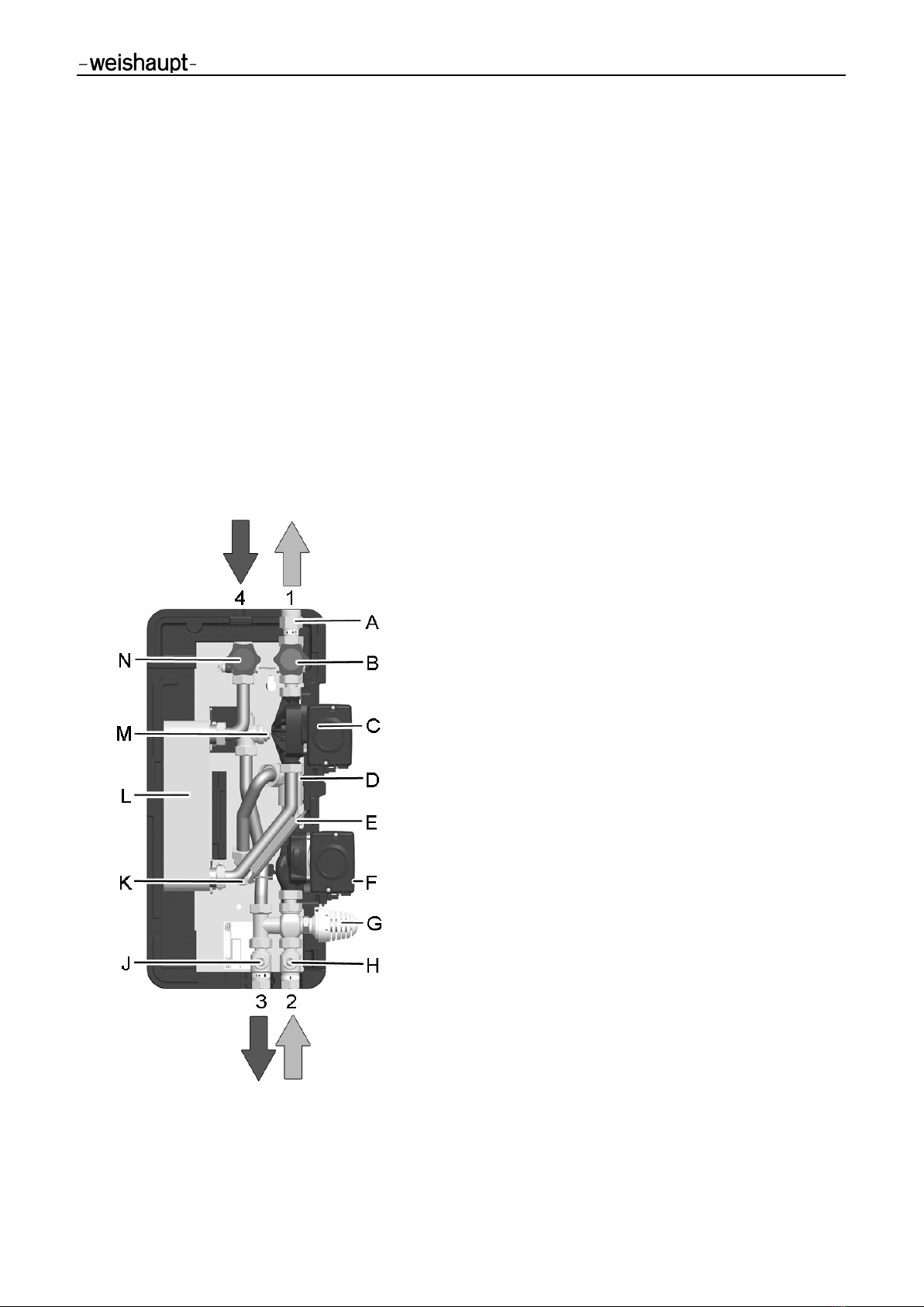
Product description............................................................................................ 7
3.1
Function........................................................................................................8
3.2
Technical data of the circulation stations ......................................................9
3.3
Technical Data Pumps................................................................................10
3.4
PWM input signal (solar profile) ..................................................................10
3.5
Hydraulilc performance data.......................................................................11
4
Dimensioning and Planning ............................................................................. 12
5
Installation ...................................................................................................... 14
5.1
Assembly ....................................................................................................14
5.2
Connection..................................................................................................15
5.3
Controller connection..................................................................................16
5.4
Electrical connection of the solar controller WRSol2.1................................16
6
Operation........................................................................................................ 16
7
Commissioning ............................................................................................... 17
7.1
Filling the primary circuit.............................................................................18
7.2
Commissioning the controller......................................................................19
7.3
Venting the circulation station.....................................................................19
7.4
Setting the temperature ..............................................................................20
7.5
Setting the pump revolution speed .............................................................20
8
Maintenance ................................................................................................... 20
9
Spare parts ..................................................................................................... 21
9.1
Spare parts list WHI circuload 9 #1 (40900015152) ...................................21
9.2
Spare parts list WHI circuload 9 #2 (40900015162) ...................................22
10
Commissioning log.......................................................................................... 23

Assembly and installation instructions
Circulation station WHI circuload 9 #1; Circulation station WHI circuload 9 #2
1 Information for the user
83288702
▪ 1/2014-02 ▪ Ext. PAW
4-24
1
Information for the user
These installation and operation instructions form part of the device and must be stored
at the place of use.
Carefully read these instructions before installation and commissioning.
1.1
User guidance
1.1.1
Symbols
DANGER
Immediate danger of high risk.
Non-observance will result in serious injuries or death.
WARNING
Danger of medium risk.
Non-observance can lead to environmental damage,
severe physical injuries or death.
CAUTION
Danger of low risk.
Non-observance may result in property damage or slight
to moderate injuries.
NOTICE
Important information.
1.1.2
Target group
This installation and operation
manual is addressed to operators and qualified skilled
personnel. It must be observed by anyone working on the machine.
Work on the machine may only be performed by persons that have received the required
training or instruction.
Persons with restricted ph
ysical, sensory or mental abilities may work on the machine if
supervised or instructed by an authorized person.
Children may not play with the machine.
1.2
Warranty and liability
Warranty and li
ability claims for personal and material damage are void if
they are due to
one or several of the following causes:
Use of the machine contrary to its designated use,
Non
-observance of the installation and operation instructions,
Operation of the machine with non
-operational safety or protective devices,
Contin
ued use despite the presence of a defect,
Improper assembly, commissioning, operation and maintenance of the machine,
Unauthorised modification of the machine,
Installation of additional components that were not tested together with the machine,
Repairs
carried out incorrectly,
Failure to use Weishaupt original parts
,
Defects in the supply lines,
Force majeure.

Assembly and installation instructions
Circulation station WHI circuload 9 #1; Circulation station WHI circuload 9 #2
2 Safety
83288702
▪ 1/2014-02 ▪ Ext. PAW
5-24
2
Safety
2.1
Designated use
The circulation station must only be installed in heating stations between the buffer tank
and the
domestic water circuit. Due to its construction, it must only be installed and op-
erated in a
vertical position. The technical limit values specified in this instruction must
be considered.
Use only original accessories in connection with the circulation station.
Using the station contrary to its designated use will invalidate all liability claims.
The wrapping materials are made of recyclable materials that can be recycled by sta
n-
dard recycling operations.
2.2
Safety instructions
The following must be observed during installation and commissioning:
•Relevant local and national regulations
•
Accident prevention regulations of the employers' liability insurance association
•Instructions and safety instructions mentioned in these instructions
CAUTION
Risk of burns!
The valves and fittings and the pumps can become heated up to
more than 95 °C during operation.
The insulation shell must remain closed during operation.
NOTICE
Material damage due to mineral oils!
Mineral oil products cause permanent damage in the material,
resulting in its sealing characteristics getting lost.
We cannot be held liable for damage caused by seals
damaged in this way, and nor will we give warranty
replacement for such parts.
It is imperative to prevent the EPDM from making contact
with substances containing mineral oils.
Use a silicone- or polyalkylene-based lubricant free of
mineral oil such as Unisilikon L250L and Syntheso Glep
1 from Klüber or a silicone spray.
NOTICE
Malfunctions!
The circulation station must be integrated into the
potential equalisation of the electrical installation.
If this is not guaranteed by the connected pipework then
establish a correct potential equalisation connection to
the main potential connection.

Assembly and installation instructions
Circulation station WHI circuload 9 #1; Circulation station WHI circuload 9 #2
2 Safety
83288702
▪ 1/2014-02 ▪ Ext. PAW
6-24
2.3
Safety measures
Immediately eliminate safety
-relevant defects and replace safety-relevant components
when they have reached the end of their service life due to their construction.
2.4
Electrical connection
When performing any work on live parts:
Observe the accident
prevention regulations BGV A3 and local regulations,
Use tools according to EN 60900.
2.5
Structural modifications
Conversion measures are only allowed after prior approval in writing by the
Max Weishaupt GmbH.
Additional components may only be
installed if they were not tested together with the
machine. Use only Weishaupt original parts.
2.6
Disposal
Dispose of the materials used properly and in an environmentally compatible manner.
In doing so, observe local regulations.

Assembly and installation instructions
Circulation station WHI circuload 9 #1; Circulation station WHI circuload 9 #2
3 Product description
83288702
▪ 1/2014-02 ▪ Ext. PAW
7-24
3
Product description
The circulation station is a pre
-assembled group of valves and fittings checked for leaks
for transferring the heat between the buffer tank and
domestic water circuit.
It contains a preset controller as well as important fittings for operating the system:
•Ball valves in the primary circuit
•Piston valves in the secondary circuit
•Pre-assembled controller
•Temperature sensors at the circulation inlet, the circulation outlet and on the
heating return
•FlowRotor with Hall sensor and temperature sensor on the heating
supply (only
WHI circuload 9 #2)
•Lockable primary pump
•Vent plug on the heat exchanger
•
Thermal mixing valve for limiting the circulation temperature
Connections
1
Secondary side: circulation outlet
2
Primary side: supply from buffer tank
3
Primary side: return to buffer tank
4
Secondary side: circulation inlet
Equipment
A
Check valve
B
Piston valve with temperature sensor
(circulation outlet)
C
Secondary pump
D
FlowRotor with Hall sensor (only WHI circuload 9 #2)
E
Strap-on sensor for thermostat controller
F
Primary pump
G
Thermostat controller
H
Ball valve
J
Ball valve with check valve
K
Temperature sensor (only WHI circuload 9 #2)
L
Heat exchanger
M
Temperature sensor
N
Piston valve with temperature sensor
(circulation inlet)

Assembly and installation instructions
Circulation station WHI circuload 9 #1; Circulation station WHI circuload 9 #2
3 Product description
83288702
▪ 1/2014-02 ▪ Ext. PAW
8-24
3.1
Function
The WHI circuload 9 circulation stations are used in domestic water networks in order to
cover the loss of heat of the circulation line from a heat storage device using a
heat
exchanger.
WHI circuload modules are integrated into the
domestic water system parallel to the
WHI freshaqua or WHI load modules. The direct supply of the modules with hot water
from the buffer tank guarantees an energy and cost
-optimised operation of the
circulation
system.
The return line of the circuload modules can be integrated into the buffer tank / tanks
independent of the return line of the WHI freshaqua or WHI load modules. A mixture of
hot and cold water is therefore reduced to a minimum so that
the degree of utilisation of
the entire system improves compared with systems without separate circulation module.
The WHI circuload 9 #2 module is also equipped with a heat flow meter in the heating
circuit in order to allow for a simple balancing of the
energy required.

Assembly and installation instructions
Circulation station WHI circuload 9 #1; Circulation station WHI circuload 9 #2
3 Product description
83288702
▪ 1/2014-02 ▪ Ext. PAW
9-24
3.2
Technical data of the circulation stations
Dimensions
WHI circuload 9 #1
WHI circuload 9 #2
Total height
645 mm
Total width
358 mm
Total depth
255 mm
Centre distance, top
81 mm
Centre distance, bottom
50 mm
Primary pipe connection
(storage tank circuit)
G ¾" female thread
Secondary pipe connection
(WHI circuload)
G 1" male thread, flat sealing
Operating data
Max. admissible pressure
primary: 6 bars, secondary: 10 bars
Operating temperature
2 – 95 °C
Max. power Q
max
9 kW at Flow
prim.
65° / DHW
sec.
60°
Flow rate at Q
max
primary: 900 l/h, secondary: 1550 l/h
Operating temperature sensors
-25 °C to +120 °C
Equipment
Primary pump
High-efficiency pump with PWM control, 3-70 W
Secondary pump
High-efficiency pump with PWM control, 3-70 W
Heat exchanger
30 plates
Flow rate sensor
/
Primary: FlowRotor,
measuring range: 2-50 l/min,
55 pulses/litre
Temperature sensor primary: 1 x NTC 5K,
secondary: 2 x NTC 5K
primary / secondary: 2 x NTC 5K each
Check valve (in the ball valve)
primary: 1 x 200 mm wc, can be opened
secondary: 1 x 200 mm wc
Material
Valves and fittings
Brass
Seals: O-ring
EPDM
Flat sealing
AFM 34, free of asbestos
Check valves
Hostaform
Pipes
1.4401 (AISI 316)
Insulation
EPP,
λ
= 0.038 W/(m K), fire class B2
Heat exchanger Plates + connecting pieces: 1.4401 (AISI 316)
Solder: 99.99% pure copper
Admissible medium primary: heating water according to VDI 2035 / Ö-Norm H 5195-1
secondary: domestic water with max. chloride content: <80 ppm

Assembly and installation instructions
Circulation station WHI circuload 9 #1; Circulation station WHI circuload 9 #2
3 Product description
83288702
▪ 1/2014-02 ▪ Ext. PAW
10-24
3.3
Technical Data Pumps
Grundfos UPM2 15-75 LowFlow
Grundfos UPM2 15-75 CIL
Length
130 mm
Connections
1" male thread
Protection class
IP 44
Max. pressure
1.0 MPa (= 10 bars)
Max. temperature
95 °C TF 95
I (1/1)
0.04-0.52 A
P1
3-70 W
Use in
WHI circuload 9 #1
Prim
Sec
WHI circuload 9 #2
Prim
Sec
Prim = Primary side (accumulator circuit) / Sec = Secondary side (circulation)
3.4
PWM input signal (solar profile)
PWM input
signal [%]
Pump status
< 6 Standby
6-8 Hysteresis
9-15 Min.
speed
16-90 Linear increase in
speed from rpm
min. to rpm max.
91-100 Max.
speed
Speed
PWM input signal [%]
Min.
Stop
Max.

Assembly and installation instructions
Circulation station WHI circuload 9 #1; Circulation station WHI circuload 9 #2
3 Product description
83288702
▪ 1/2014-02 ▪ Ext. PAW
11-24
3.5
Hydraulilc performance data
WHI circuload 9 #1 or WHI circuload 9 #2
Heating UPM2 15-75 LowFlow
Circulation UPM2 15-75 CIL
Flow rate [l/h]
Residual delivery pressure or pressure drop [mbars]

Assembly and installation instructions
Circulation station WHI circuload 9 #1; Circulation station WHI circuload 9 #2
4 Dimensioning and Planning
83288702
▪ 1/2014-02 ▪ Ext. PAW
12-24
4
Dimensioning and Planning
The WHI circuload is a circulation station that heats the
domestic water according to the
continuous flow heater principle.
For the perfect function of the circulation station, the system must fulfil certain
requirements. Take a little time for the planning before the assembly.
Assembly example 1: circulation station from standby buffer
When using the WHI circuload in combination with a standby buffer, hydraulic version 38
must be set in the
controller.
Please note:
Due
to their construction, the WHI circuload modules reduce the precipitation of scale in
the heat exchanger. For systems with a high total domestic water hardness and/or high
temperatures, a water treatment is recommended, in order to prevent scale formation.
Circulation station
Fresh water station
Standby heat
storage device
Heat generator

Assembly and installation instructions
Circulation station WHI circuload 9 #1; Circulation station WHI circuload 9 #2
4 Dimensioning and Planning
83288702
▪ 1/2014-02 ▪ Ext. PAW
13-24
Assembly example 2: circulation station from pre-heat buffer
The circulation stations are preset in the factory for using the pre
-heat buffer
(hydraulic version 39 on the controller).
You can obtain further information on this in the enclosed controller manual or the
planning documents for large solar systems.
Circulation station
Fresh water station
Solar heat
storage device
Heat generator
WAS

Assembly and installation instructions
Circulation station WHI circuload 9 #1; Circulation station WHI circuload 9 #2
5 Installation
83288702
▪ 1/2014-02 ▪ Ext. PAW
14-24
5
Installation
The domestic water connection must be carried out according to the relevant standards
(e.g., DIN 1988)!
NOTICE
Material damage!
The safety valve integrated into the station does not
replace the safety equipment of the domestic water
connection according to DIN 1988.
The safety valve merely protects the station from excess
pressures when maintenance is required.
5.1
Assembly
NOTICE
Material damage!
In order to avoid damaging the system, the installation
site must be dry, structurally safe and frost-free.
Furthermore, access to the closed-loop control and
safety equipment must be guaranteed at all times
during operation!
If tapping points are connected to the same network
as the circulation station, in which pressure surges are
possible (e.g., flushing valves, washing machines or
dishwashers), we recommend the installation of water
hammer dampers near the device causing the pressure
surges.
WARNING
Risk to life and limb due to electric shock!
Prior to performing electrical work on the controller,
de-energise the system.
For more information, see enclosed installation and
operation instructions of the station controller.
Connect the circulation station to the power supply sys-
tem (230 V, 50 Hz) only after completing all installation
tasks, filling and flushing. This avoids an unintentional
start of the motors.
Hot water
generator
Service water fitting
Drain valve
Safety valve
Non-return valve
Pressure-reducing valve, if necessary
Test valve
Shut-off valve
Hot
water
Cold
water

Assembly and installation instructions
Circulation station WHI circuload 9 #1; Circulation station WHI circuload 9 #2
5 Installation
83288702
▪ 1/2014-02 ▪ Ext. PAW
15-24
1. Determine the installation location of the circulation station near to
the buffer tank. With longer connecting lines, the transfer capacity
is reduced due to higher pressure losses.
2. Transfer the dimensions for the drill holes onto the wall.
3. Drill holes and insert the enclosed wall plugs. Make sure that the
ground has sufficient load-carrying capacity.
4. Screw in the top screw into the plug until about 40 mm protrudes
from the wall.
5. Pull off the front shell.
6.
Hang the circulation station on the screws and insert the screws at
the bottom. Tighten the screws so that the insulation on the sides
rest against the wall.
5.2
Connection
Pipe the circulation station with the system according to the diagram below.
Pipe gap from the wall
(secondary) = 107 mm
1
Secondary side
:
circulation outlet
connection 1" male thread, flat sealing
2
Primary side:
supply from buffer tank,
¾" female thread,
piping
minimum DN 20, 22 x 1 mm,
recommended DN 25, 28 x 1.5 mm
3
Primary side:
return to buffer tank,
¾" female thread,
piping
minimum DN 20, 22 x 1 mm,
recommended DN 25, 28 x 1.5 mm
4
Secondary side
:
circulation inlet
connection 1" male thread, flat sealing
Pipe gap from the wall
(primary) = 67 mm

Assembly and installation instructions
Circulation station WHI circuload 9 #1; Circulation station WHI circuload 9 #2
7 Commissioning
83288702
▪ 1/2014-02 ▪ Ext. PAW
16-24
5.3
Controller connection
WARNING
Risk to life and limb due to electric shock!
Prior to performing electrical work on the controller,
de-energise the system.
For more information, see enclosed installation and
operation instructions of the station controller.
Connect the circulation station to the power supply
system (230 V, 50 Hz) only after completing all
installation work, filling and flushing.
This avoids an unintentional start of the motors.
The circulation station is pre-wired in the factory.
5.4
Electrical connection of the solar controller WRSol2.1
Terminal
Acronym
Description
Execution
L/N
230V
Mains connection 230 V
on site
1/N
PZWP
Primary circuit pump
prewired
2/N
PZW
Secondary circuit pump
prewired
11/┴
TZW
Secondary circuit return sensor
prewired
12/┴
TZWA
Secondary circuit flow sensor
prewired
16/┴ *
TO1
Heat source temperature
on site
17/┴
PWM2
PWM control signal for secondary pump
prewired
18/┴
PWM1
PWM control signal for primary pump
prewired
19/┴
TPR
Primary circuit return sensor
prewired
20/┴ **
TPV
Primary circuit flow sensor
prewired
21/25/┴ **
V1
Volume pulse input collector loop
prewired
*
required when using the WHI circuload in combination with a pre-heat buffer
(hydraulic version 39).
** only with WHI
circuload 9 #2
6
Operation
A detailed description of the operation of the controller can be found in the enclosed
controller manual.
Solar controller WRSol 2.1 pre
-settings
•Hydraulic version 39
•eBUS address 3
•Heat flow meter option (with WHI circuload 9 #2)
•Pulse rate 55 pulses/litre (with WHI circuload 9 #2)

Assembly and installation instructions
Circulation station WHI circuload 9 #1; Circulation station WHI circuload 9 #2
7 Commissioning
83288702
▪ 1/2014-02 ▪ Ext. PAW
17-24
7
Commissioning
Observe the following safety instructions regarding the commissioning of the station:
NOTICE
Note!
Open the valves in the lines and in the module
slowly
in order to
avoid pressure surges.
Check valve operation
The primary circuit is equipped with a check valve in ball valve (J) in order to prevent
undesired gravity circulation.
The check valve must be opened for venting and flushing the system.
For this purpose turn ball valve (J) to position 45°
. The check valve is not in operation.
All ball valves and valves must be opened completely
for operating the system
(position 0°
).
Ball valve with integrated check valve
(Normal direction of flow in the picture: downstream)
0°
45°
90°
Check valve in operation,
flow in flow direction only.
Check valve not in operation,
flow in both directions.
Ball valve closed,
no flow.
To actuate the ball valve, a handle is included in the
delivery.

Assembly and installation instructions
Circulation station WHI circuload 9 #1; Circulation station WHI circuload 9 #2
7 Commissioning
83288702
▪ 1/2014-02 ▪ Ext. PAW
18-24
7.1
Filling the primary circuit
WARNING
Risk of scalding from hot water!
The system is under pressure. When opening the manual air vent,
water up to 90 °C may escape at the manual air vent that could
lead to personal injury.
Open the manual air vent slowly and at a safe distance.
With (partially) filled tank
During the filling and flushing of the circulation station, air can be vented using the
manual air vents (O) and (P).
1. Open ball valves (H) and (J) slowly by turning them to the
45°
position.
2. Carefully open the manual air vents (O) and (P) using a square key and allow
the air to escape.
3. Close manual air vents (O) and (P).
4. After venting, check the operating pressure of the primary circuit and, where
necessary, increase the pressure.
5. Open ball valves (H) and (J) completely by turning them to the
0°
position.

Assembly and installation instructions
Circulation station WHI circuload 9 #1; Circulation station WHI circuload 9 #2
7 Commissioning
83288702
▪ 1/2014-02 ▪ Ext. PAW
19-24
7.2
Commissioning the controller
WARNING
Risk to life and limb due to electric shock!
Check whether the sensors and pumps have been
connected to the controller and the controller housing
is closed.
Do not apply voltage to the controller before that.
A detailed description of the commissioning of the controller can be found in the
enclosed controller manual.
1. Makes sure that the circulation station is integrated correctly into the potential
equalisation of the system.
2. Slowly open the piston valves on the secondary side (B) and (N).
3. Connect the circulation station to the power supply system (230 V, 50 Hz).
The circulation station is pre-set in the factory for operation in combination with
a pre-heat buffer (hydraulic version 39). The pre-setting must be adapted
according to the system depending on the application.
4. Carefully open and close the venting device on the check valve (A).
5. Select the manual mode for the secondary pump in the selection menu of the
controller (see controller manual).
Switch on the PWM signal of the secondary pump ("100 %").
6. Allow the secondary pump to run for 3 minutes.
7. During this time, vent the circulation station several times on the vent plug of
the check valve (A).
8. When you no longer hear any air noises, switch off the secondary pump.
7.3
Venting the circulation station
1. Allow the primary and secondary pumps to run for several minutes in manual
mode.
2. Vent the primary side carefully via the manual air vents (O) ans (P).
3. Vent the secondary side carefully via the vent valve on the check
valve (A).
4. After venting, check the operating pressure of the tank and, where necessary,
increase the pressure.
5. Set the controller to automatic mode.
6. Check the station for leaks and set the desired temperature on the controller
(see following chapter).
7. The circulation station is now ready for operation.

Assembly and installation instructions
Circulation station WHI circuload 9 #1; Circulation station WHI circuload 9 #2
7 Commissioning
83288702
▪ 1/2014-02 ▪ Ext. PAW
20-24
7.4
Setting the temperature
The desired (maximum) circulation temperature can be set on the thermostat controller.
WARNING
Risk of scalding from hot water!
In order to prevent scalding at the tap, the maximum hot
water temperature should not exceed 60 °C.
The thermostat controller is infinitely variable. When delivered, a flow temperature of
approx. 60
°C is pre-set. If, for example, the temperature at the circulation outlet is too
high, the
supply temperature can be regulated down on the thermostat controller.
The follow
ing table gives an overview of the thermostat controller setting range:
Setting range on the
thermostat controller
Circulation temperature
5
~50 °C
6
~60 °C
7
~70 °C
7.5
Setting the pump revolution speed
In order to increase the energy efficiency of the circulation station, the revolution speed
of the pumps must be adapted to the system
-specific conditions (pressure drop in the
pipework
). See the controller manual as to how the revolution speed is adapted in the
controller.
8
Maintenance
The WHI
circuload modules are low in maintenance. However, as part of the annual
inspection of the domestic water system, the following items should be
checked/observed:
•Check all connections for leaks
•Check the safety equipment
•Perform a functional check and check the setting parameters
•Plausibility check of the control parameters and nominal values
•Check the heat exchanger for dirt and functioning
We recommend concluding a maintenance agreement.
This manual suits for next models
1
Table of contents
Other Weishaupt Water System manuals
Popular Water System manuals by other brands

Everpure
Everpure Coldrink 1-MC2 System EV9328-01 Specification sheet

Filtrete
Filtrete 4US-MAXS-S01 Installation and operating instructions

OMEGA AIR
OMEGA AIR AOK 20SS Installation and operating manual

Cooke
Cooke WaterWitch Product support guide

Nexus
Nexus JP-103 Operation manual

Waters
Waters ACQUITY UPLC I-Class Series System guide

Wilo
Wilo H Series Installation and operating instructions

FLOWMARK
FLOWMARK Mark-II-SC Installation & operation manual

salmson
salmson ZEN O HOME Installation and starting instructions

OMEGA AIR
OMEGA AIR MDHI installation manual

EINHELL
EINHELL 41.731.90 Original operating instructions

Primochill
Primochill Myriad manual