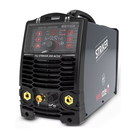
Weldcote MIG STRIKER 200 User manual

WELDING FOR WELL-BEING
MIG
STRIKER
200
Quick Guide Manual
ALUMINIUM

2
//
SAFETY WARNING
On the process of welding or cutting, there will be possibility of injury, so please
take protection into consideration during operation. For more details please review
the Operator Safety Guide, which complies with the preventive requirements of the
manufacturer.
Electric shock - May lead to death!!
• Set the earth tting according to applying standard.
• Do not touch the bare electric parts and electrode with uncovered skin, wet gloves or clothes.
• Make sure you are insulated from the ground and the workshop.
• Make sure you are in safe position.
Gases and fumes - May be harmful to health!!
• Keep your head out of the gases and fumes.
• When arc welding, ventilators or air extractors should be used to avoid breathing gases.
Arc rays - Harmful to your eyes, burn your skin
• Wear suitable protective mask, light lter and protective garment to protect eyes and body.
• Prepare suitable protective mask or curtain to protect looker-on.
Fire
• Welding sparks may cause a re, make sure there are no ammable objects or chemicals nearby.
Noise - Excessive noises will be harmful to hearing
• Use haring protection or others means to protect ear.
• Warn looker-on that noise is harmful to hearing.
Having trouble? Connect with authorized professionals
• If trouble happens during installation and operation, please follow this manual instruction
to check up.
• If you fail to fully understand the manual, or fail to solve the problem with the instruction, you
should contact the suppliers or the service center for professional help.
WARNING!
Thermal Magnetic Auto Circuit Breaker protecting switch
should be used with the machine.

//
3
• Repair and maintenance to be performed by authorized personnel only.
• The welding machine is to be maintained in good operational conditions (dry and clean).
• The welding machine is not to be positioned in a closed space or next to a wall while welding
in order to avoid problems with venting.
• The welding machine is to be properly connected to the power grid.
• avoid pulling on the power cable when moving the welding machine.
• the welding handle and work cable are to be properly maintained.
• Electricity is dangerous and loose connections can lead to injury and poor welding.
The welding arc emits sparks, fumes and radiation
• Remove all ammable materials and items from your work area.
• Ensure proper ventilation at the work area.
• Do not weld tanks or pipes that contain or used to contain ammable liquid or gas (danger of
explosion or re) or were cleaned by chlorine-based detergents (danger of toxic fumes).
• Avoid coming in direct contact with the welding circuit. The open circuit voltage between the
electrode holder, the work cable and the work piece is dangerous.
• Do not weld when it is raining or in wet or damp places.
• Always use protective equipment DIN 9-10, including long sleeved pants and vest, gloves,
welding helmet of proper rating and hat. Avoid exposing the skin to the welding UV radiation.
The radiation emitted by the welding arc can cause damage to the eyes and burns to
the skin.
these stay hot for a relatively long time.
The welding fumes produced when welding are dangerous.
Every electrical shock is dangerous.
Avoid direct exposure of the skin from the welding arc at a range of 15 meters.
Take proper precautions to protect yourself and others from the potential dangers of
the welding arc.

4
//
2.0 GENERAL INFORMATION
1. Digital current display
2. Welding current adjustment
3. Digital voltage display / wire speed
4. Dial for adjusting voltage/down slope/arc force
5. POWER ON indication light - is on when the welding machine is connected to a live socket
and is on.
6. ALARM indication light - is on in case of under voltage, over current, or over heat, this pilot
lamp indicates when lit that the protection of the machine has been activated.
7. Inductance adjusting knob (STICK: adjust the arc force; TIG: adjust down slope time; MIG: ne
adjust welding voltage 10~25V).
8. Wire diameter selection - voltage and amperage automatically adjust according to the
diameter. For manual selection choose MAN. Voltage and Wire Speed still operate, but are
pre-set to the recommended values.
9. Welding material selection. MS - Mild Steel, Al - Aluminum, SS - Stainless Steel.
10. Manual/Automatic (2T/4T) operation mode selection
11. Welding mode selection (MIG/TIG/Stick)
12. MIG gun quick connector - the MIG welder’s positive polarity output.
13. Positive terminal quick connection (+)
14. Shield gas connector - Is connected to the gas input pipe of the torch
15. TIG gun quick connector
16. Negative terminal quick connection (-)
17. Shield gas input joint to the gas cylinder
18. ON/OFF switch
19. Input power cable connection
20. Burn Back adjustment - increase to prevent wire sticking to the workpiece.
21. Spool Gun / MIG Gun selector switch - select according to the gun used.
22. Polarity selector - jumper plate to be placed according to welding polarity needed (change
to "-" position, and earth cable connects to "+" on front panel when using self-shielding wire).
23. 11lb spool (8" outer diameter).
24. Drive Roll - groove diameter to be according to wire diameter used.
Single phase inverter with voltage reduction for direct current welding using coated electrodes,
MIG spools and TIG rods.

//
5

6
//
• PFC - correction and dumping circuits in the machine increase power eciency, reducing input
power requirements, and stabilizing welding current.
• MIG ALUMINUM - Welding with aluminum spools or spool gun with Synergic settings.
• HOT START - Easy ignition of the welding arc.
• ARC FORCE - Prevents sticking of the electrode to the workpiece.
• SPOOL GUN READY - Spool gun compatible (purchased separately).
• VRD - Reduce Voltage at no-load condition for safer work.
• SMART FAN - Power saving and reduction of dust as well as improved fan working life.
• DUAL VOLTAGE - Automatically identify the power grid voltage (120V or 230V) and operates
accordingly 120V to 230V adapter included.
MIG STRIKER 200PARAMETERS
STICKTIGMIG
1~120±10% 1
1~230±10%
28 1
30.2
25.5 1
20.3
32 1
26.1
3.4 1
6.7
2.9 1
4.5
3.9 1
5.7
10~110 1
10~200
10~140 1
10~200
10~140 1
10~200
--10~26
50% 110A 1
60% 95A 1
100% 85A 1
60% 140A 1
100% 115A 1
35% 140A 1
60% 115A 1
100% 100A 1
25% 200A
60% 140A
100% 100A
25% 200A
60% 140A
100% 100A
25% 200A
60% 140A
100% 100A
79 1
84
76 1
81
75 1
84
0.99
AF
MS: .023/030/035/045 Al: 035/045 Flux: Wire Diameter
F
39.2Net Weight
18.5”×8.8”×16.6”
(length×width×height)
21.6”×13.8”×11.4”
(length×width×height)
1

//
7
Before connecting to the power grid, verify the supply voltage is in range of the machine parameters.
• The power cable plug is to be connected to standard approved socket, with the proper protections.
• The ground line (green & yellow) is to be connected to the grounding pin.
The machine is designed to use 11lb spools (8" outer diameter)
The wire spools are not supplied with the machine and must be purchased separately.
Make sure the shielding gas and electrical power are disconnected.
• Use a CO2 or mixed gas Cylinder equipped with a pressure regulator. Connect the exible hose
between the regulator and the machine (17). Tighten the bands.
• Connect the ground cable quick connection between the machine (negative terminal (16)
when using solid wire) and the work piece.
• Mount the wire spool (B) over the shaft (C) and tight with the nut (F).
• Choose the proper feeder grooved wheel (1 or 2) according to the wire diameter used.
• Release the screw in the feeder mechanism and insert the wire through the tube. Close and
tighten the screw to have the feeder wheel hold the wire in place.
• Connect the MIG torch cable quick connector over the protruding wire. Feed the wire all
through to the torch, and screw a contact tip over it.

8
//
A. Select MIG mode with the process selection control (11).
B. In most cases the MIG polarity selector (22) is to be connected to the negative position (-),
as shown in the sketch. If in doubt, consult the wire manufacturer.
C. Fit the MIG Gun to the power source using the front panel connection socket (12).
D. Connect the work lead to the negative welding terminal (16). If in doubt, consult the wire
manufacturer. Welding current ows from the Power Source via heavy duty bayonet type
terminals. It is essential, however, that the male plug is inserted and turned securely to achieve
a sound electrical connection.
E. Fit the welding grade shielding gas regulator/owmeter to the shielding gas cylinder, then
connect the shielding gas hose from the rear of the power source (17) to the regulator/
owmeter outlet, using the supplied quick-connect adaptor.
F. Select manual or automatic operation (10).
G. Select workpiece material (9).
H. Select wire diameter of the spool installed (8)
I. Make sure the feed roll used corresponds to the same diameter (24)
J. Set the Welding Gun Switch located inside the wire drive compartment (21), to MIG GUN.
A. Select MIG mode with the process selection control (11).
B. In most cases the MIG polarity selector (22) is to be connected to the negative position (-),
as shown in the sketch. If in doubt, consult the wire manufacturer.
C. Fit the Spool Gun to the power source using the front panel connection socket (12).
D. Connect the work lead to the negative welding terminal (16). If in doubt, consult the wire
manufacturer. Welding current ows from the Power Source via heavy duty bayonet type
terminals. It is essential, however, that the male plug is inserted and turned securely to achieve
a sound electrical connection.
E. Fit the welding grade shielding gas regulator/owmeter to the shielding gas cylinder, then
connect the shielding gas hose from the rear of the power source (17) to the regulator/
owmeter outlet, using the supplied quick-connect adaptor.
F. Select manual or automatic operation (10).
G. Select workpiece material (9).
H. Select wire diameter of the spool installed in the SPOOL GUN(8)
I. Set the Welding Gun Switch located inside the wire drive compartment (21), to SPOOL GUN.

//
9
A. Follow the above steps according to the type of welding gun used (3.2.1 or 3.2.2), with the
following dierences is steps B and E:
B. In most cases the MIG polarity selector (22) is to be connected to the negative "-", and earth
cable connects to "+" on front panel. If in doubt, consult the wire manufacturer.
E. No shielding gas is needed.
The start current and crater current can be pre-set. This function can compensate the possible
crater that appears at the beginning and end of the welding.
Introduction:
0: Press and hold the gun switch, Electromagnetic gas valve is turned on.
The shielding gas starts to ow;
~ 0t1: Pre ow time, adjustment range of pre ow time :0.1~1.0S;
~ t1: Striking success, adjustment range of start current: 5~200A;
~ t2: Release the gun switch, the output current slopes up from start current;
t2~t3: Output current slopes up to the setting current value; adjustment range of up slope
time 0~10.0S ;
t3~t4: Welding process. During this period, the gun switch is released;
Note: the output current is DC current;
t4: Repress down the gun switch, the output current slopes down to crater current;
t4~t5: Down slope time, adjustment range of down slope time: 0~10.0S;
t5~t6: Crater current holds time; adjustment range of crater current: 5~200A;
t6: Release switch, stop arc, gas will post ow;
t6~t7: Post ow time, adjustment range of post ow time: 0.1~10.0S;
t7: Electromagnetic valve is closed and stop argon owing. Welding is nished.
TIG short welding (2T)
Introduction:
0: Press and hold the gun switch, Electromagnetic gas valve is turned on. The shielding gas starts
to ow;
~ 0t1: Pre ow time, adjustment range of pre ow time: 0.1~1.0S;
t1~t2: Striking success, the output current slopes up to the setting current from minimum

10
//
current (5A)
t2~t3: During the whole welding process, the gun switch is pressed and held without releasing;
t3: Release the gun switch, the output current slopes down;
t3~t4: The output current slopes down to minimum current (5A), stop arc; adjustment range of
down slope time: 0~5S;
t4~t5: Post ow time, adjustment range of post ow time: 0.1~10.0S;
t5: Electromagnetic valve is closed and stop argon owing. Welding is nished.
Short circuit protect function:
1. TIG /DC/LIFT: If the tungsten electrode touches the workpiece when welding, the current will
drop to 30A, which can reduce the tungsten spoilage and signicantly prolong the life of the
tungsten electrode and prevent tungsten clipping.
2. STICK operation: if the electrode touches workpiece over two seconds, the welding current
will drop to 0 automatically to protect the electrode.
Notices:
• Check the condition of welding and connection units rstly, otherwise there will be malfunction
such as ignition spark/gas leakage/out of control and so on.
• Check that whether there is enough Argon gas in the shield gas cylinder, you can test the
electromagnetic gas valve through the switch on the front panel.
• The ow rate is set according to the welding power used in the job. Turn the regulation
screw to adjust the gas ow which is shown on the gas hose pressure meter or the gas bottle
pressure meter.
A. Connect the Electrode Holder lead to the positive welding terminal (13).
If in doubt, consult the electrode manufacturer. Welding current ows from the Power Source
via heavy duty bayonet type terminals. It is essential, however, that the male plug is inserted
and turned securely to achieve a sound electrical connection.
B. Connect the work lead to the negative welding terminal (16). If in doubt, consult the electrode
manufacturer. Welding current ows from the power source via heavy duty bayonet type
terminals. It is essential, however, that the male plug is inserted and turned securely to achieve
a sound electrical connection.
C. Select STICK mode with the process selection control (11).

//
11
The work clamp is to be connected directly to the work piece or the work table with good
electrical continuity to the work piece.
Careful! Avoid using coated or non-metallic, non-conducting work-benches.
This cable has a special handle that holds the exposed part of the coated electrode.
Used for welding with wire spools.
Used for welding with ller rods using a Tungsten Electrode.
You must always use a welding helmet to protect your eyes from the radiation emitted from the
welding arc. Using a welding helmet allows the welder to see the progression of the weld seam,
and keeping the correct distance from the electrode tip to the work piece.

12
//
Read this operation manual carefully before use.
Single-phase static frequency converter-transformer rectier.
Symbol of manual metal arc welding with covered electrodes.
Symbol of single-phase AC power supply and rated frequency.
1~50HZ
Do not dispose of electric tools together with domestic garbage.
Insulation class.
H
Can be used in the environment which has high risk of electric shock.
S
Do not use outdoors.
U1: Rated AV input voltage (with tolerance ±10%).
I1max: Rated maximum input current.
I1e: Maximum eective input current.
X: duty cycle. The ratio of given duration time/the full-cycle time.
Note1: This ratio shall be within 0~1, and can be indicated by percentage.
Note2: In this standard, the full-cycle time is 10min. For example, if the duty cycle is 60%, the
load-applying time shall be 6min and the following no-load time shall be 4min.
U0: No-load voltage. Open circuit voltage of secondary winding.
U2: Load voltage.
Output voltage of rated load: U2=(20+0.04I2) V.
A / V—A / V: range of current regulation and corresponding load voltage.
IP: degree of protection, such as IP21S.

//
13
• Height above sea level is below 1000m.
• Operation temperature range: -10°C+40°C / 14°F~104°F.
• Relative humidity is below 90% (200°C/68°F), relative humidity is below 50% (400°C/104°F).
• The inclination of the power source does not exceed 10°.
• Protect the machine against heavy rain or in hot circumstance against direct sunlight.
• The content of dust, acid, corrosive gas in the surrounding air or substance cannot exceed
normal standard.
• Take care that there is sucient ventilation during welding. There is at least 30cm/12" free
distance between the machine and wall.
Read this manual carefully before attempting to use the equipment.
• Connect the ground wire with the machine directly.
• In case closing the power switch, no-load voltage may be exported. Do not touch the output
electrode with any part of your body.
• Before operation, non-essential personnel should leave.
Do not watch the arc with unprotected eyes.
• Ensure good ventilation of the machine to improve duty cycle ratio.
• Turn o the machine when the operation nished to economize energy source.
• When power switch shuts o protectively because of failure. Don’t restart it until problem is
resolved. Otherwise, the range of problem will be extended.

14
//
PFC TECHNOLOGY
Reduces energy consumption up to 50% considering the model of conventional type welding
machine and enables usage of energy in high eciency and high quality.
Supply Voltage and Current over time comparison (under steady load):
Large
Energy
Loss
Welding Current stability comparison (under steady load):
Unstable
Energy
Loss

Serial Number:
Model Number:
Dealers Name:
Dealers Signature And Stamp:
Serial Number:
Model Number:
Dealers Name:
Dealers Signature And Stamp:
Customer Name:
Address:
Email:
Tel Number:
Date Of Purchase:
Customer Name:
Address:
Email:
Tel Number:
Date Of Purchase:
WARRANTY TERMS:
1. The warranty is valid for three years for any manufacturing defect.
2. This warranty is canceled if this certificate is not sent immediately upon purchase with tax
invoice attached.
3. This warranty is canceled if the machine opened or disassemble not in the company labs.
5. In any case of use other than according to instructions the manufacturer's warranty is not valid.
Please send this attachment within 14 days of purchase!
3 year warranty

The warranty is valid under the following conditions:
Weldcote Metals
www.weldcotemetals.com
DEAR CONSUMER:
Read before you turn on your device - keep this page
GENERAL INSTRUCTIONS:
keep for your reference.
Warranty coverage terms:
1. Warranty covers any manufacturing technical defects excluding breakage.
2. Warranty is void if repaired without our consent.
4. Only electronic components inside can be repaired for any manufacturing defects during warranty
period.
Weldcote Metals
704 -739- 4115
www.weldcotemetals.com
Table of contents
Other Weldcote Welding System manuals
Popular Welding System manuals by other brands

Miller Electric
Miller Electric IH owner's manual

WELDTECH
WELDTECH SC40C operating instructions

Lincoln Electric
Lincoln Electric LINC 405-S Operator's manual

STAYER WELDING
STAYER WELDING Gama PLASMA 40 COM GE operating instructions

LORCH
LORCH M-Pro BasicPlus Operation manual

Magmaweld
Magmaweld ID 300 M user manual