Weldcote TIG STRIKER 200 AC User manual

WELDING FOR WELL-BEING
TIG
STRIKER
200 AC
Quick Guide Manual
TIG WELDER

2
//
SAFETY WARNING
On the process of welding or cutting, there will be possibility of injury, so please
take protection into consideration during operation. For more details please review
the Operator Safety Guide, which complies with the preventive requirements of the
manufacturer.
Electric shock - May lead to death!!
• Set the earth tting according to applying standard.
•
Do not touch
the bare electric parts and electrode with uncovered skin, wet gloves or clothes.
• Make sure you are insulated from the ground and the workshop.
• Make sure you are in safe position.
Gases and fumes - May be harmful to health!!
• Keep your head out of the gases and fumes.
• When arc welding, ventilators or air extractors should be used to avoid breathing gases.
Arc rays - Harmful to your eyes, burn your skin
• Wear suitable protective mask, light lter and protective garment to protect eyes and body.
• Prepare suitable protective mask or curtain to protect looker-on.
Fire
• Welding sparks may cause a re, make sure there are no ammable objects or chemicals nearby.
Noise - Excessive noises will be harmful to hearing
• Use haring protection or others means to protect ear.
• Warn looker-on that noise is harmful to hearing.
Having trouble? Connect with authorized professionals
• If trouble happens during installation and operation, please follow this manual instruction to
check up.
• If you fail to fully understand the manual, or fail to solve the problem with the instruction, you
should contact the suppliers or the service center for professional help.
WARNING!
Thermal Magnetic Auto Circuit Breaker protecting switch
should be used with the machine.

//
3
2.0 SUMMARY
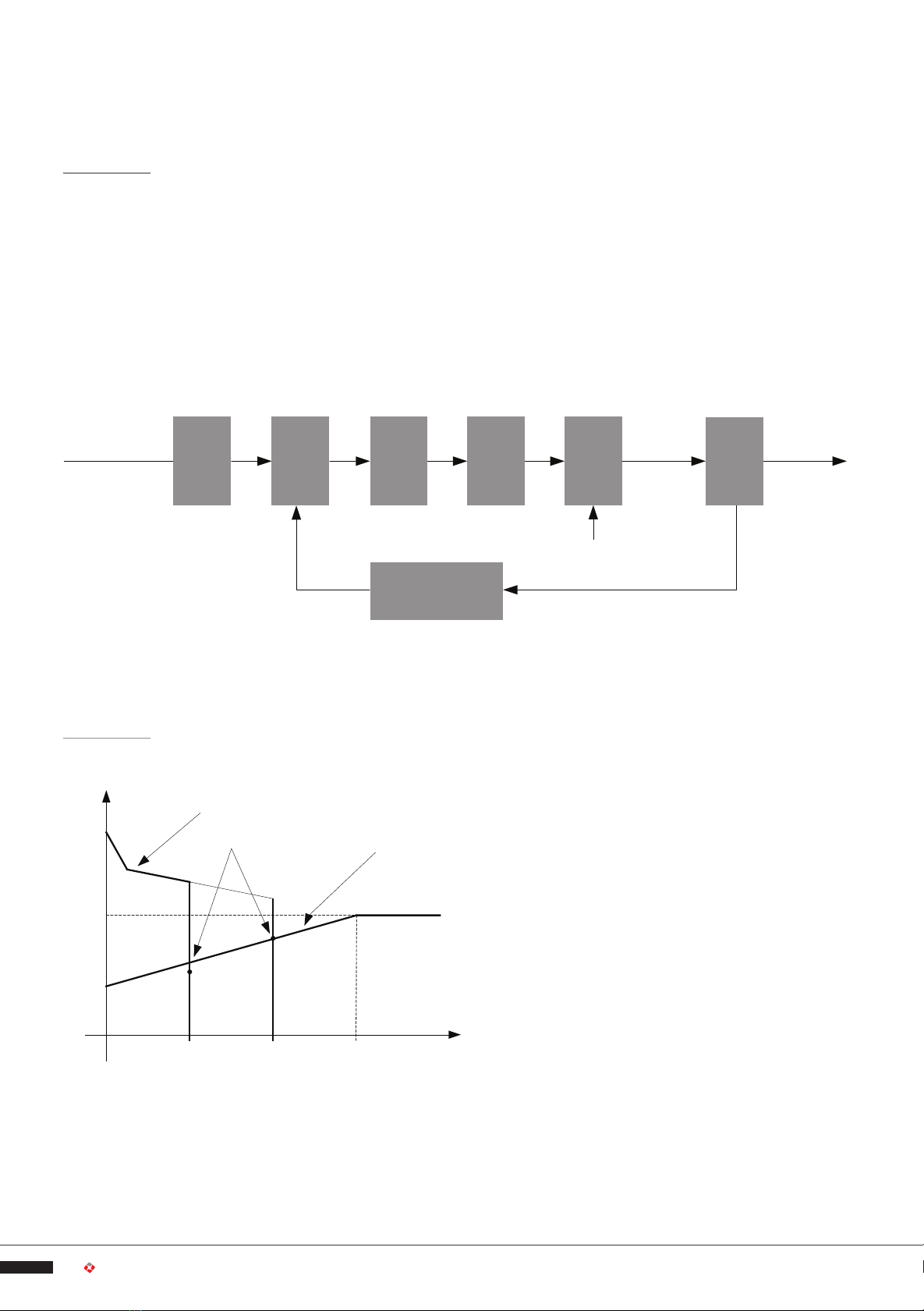
TIG STRIKER 200 AC welding machine adopts the latest pulse width modulation (PWM) technology
and insulated gate bipolar transistor (IGBT) power module, which can change work frequency to
medium frequency so as to replace the traditional hulking work frequency transformer with the
cabinet medium frequency transformer. Thus, it is characterized with portable, small size, light
weight, low consumption etc.
responds immediately to any changes.
power factor more than 0.98
for arc igniting to ensure the success ratio of igniting arc, the
reverse polarity ignition ensures good ignition behavior in TIG-AC welding.
with special means, even if arc-break occurs the HF will keep the arc stable.
If the tungesten electrode touches the workpiece when welding, the
current will drop to short-circuit current to protect tungsten.
over-voltage, over-current, and over heat indication light on the front
panel will turn on and the output current will be cut o. It can self-protect and prolong the life
of the machine.
AC inverter TIG/STICK and DC inverter TIG/STICK, Excellent performance on
Al-alloy, carbon steel, stainless steel, titanium.
According to the front panel functions, the following six welding modes can be performed:
• DC STICK
• DC TIG
• AC STICK
• AC TIG
1. For DC STICK, polarity connection can be chosen according to dierent electrodes, please
refer to 3.5;
2. For AC STICK, magnetic ow caused by invariable DC polarity can be avoided;
3. For DC TIG, DCEN is used normally (workpiece connected to positive polarity, while torch
connected to negative polarity). This connection has many advantages, such as stable welding
arc, low tungsten pole loss, more welding current, narrow and deep weld;
4. For AC TIG (rectangle wave), arc is more stable than Sine AC TIG. At the same time, you can
not only obtain the max penetration and the min tungsten pole loss, but also obtain better
cleaning eect.
TIG STRIKER 200 AC welding machine is suitable for all positions welding for various plates made
of stainless steel, carbon steel, alloyed steel, titanium, aluminum, magnesium, cuprum, etc.,
which is also applied to pipe installment, mold mend, petrochemical, architecture decoration,
car repair, bicycle, handicraft and common manufacture.
MMA Manual Metal Arc welding;
PWM Pulse-Width Modulation;
IGBT Insulation Gate Bipolar Transistor
TIG Tungsten Insert Gas welding

4
//
The working principle of TIG STRIKER 200 AC welding machines is shown as the following gure.
single-phase 115V/230V work frequency AC is rectied into DC (about 380V), then is converted
to medium frequency AC (about 44K Hz) by inverter device (IGBT module), after reducing voltage
by medium transformer (the main transformer) and rectifying by medium frequency rectier
(fast recovery diodes), then is outputted DC or AC by selecting IGBT module. The circuit adopts
current feedback control technology to insure current output stably. Meanwhile, the welding
current parameter can be adjusted continuously to meet with the requirements of welding craft.
DC
AC
DC
AC
When I2≤600A, U2=10+0.04I2(V); When I2>600A,U2=34(V).
I2(A)
2(V)
50
34
10
0600

//
5
TIG STRIKER 200 ACPARAMETERS
1~230±10%, 1~120±10%,
STICKTIGSTICKTIG
27. 3 (AC )23.7 (AC)31.9 (AC)30.3 (AC)
25.1 (DC)23.3 (DC)29.5 (DC)29 (DC)
5.8 (AC)5.0 (AC)3.7 (AC)3.7 (AC)
5.3 (DC)4.7 (DC)3.4 (DC)3.4 (DC)
45 (52)
STICKTIGSTICKTIG
DCACDCACDCACDCAC
5~17010~1705~20010~2005~10010~1005~14010~140 (A)
5~17010~1705~20010~2005~10010~1005~14010~140(A)
0~10
0~10
0.1~10
1~10
0.5~200
5~100
50~250
15~50
0~10
0~10
0~10
DC 30% 170A
AC 35% 170A
DC 25% 200A
AC 30% 200A
DC 35% 100A
AC 40% 100A
40% 140A
(40°C/104°
DC 60% 120A
AC 60% 130A
DC 60% 130A
AC 60% 140A
DC 60% 75A
AC 60% 80A
60% 110A
DC 100% 90A
AC 100% 110A
DC 100% 100A
AC 100% 110A
100% 60A100% 85A
F
17.7"×6.7"×10.6"
3.0 SUMMARY

6
//
The letter “X” stands for duty cycle, which is
dened as the proportion of the time that a
machine can work continuously within a certain
time (10 minutes). The rated duty cycle means the
proportion of the time that a machine can work
continuously within 10 minutes when it outputs
the rated welding current. The relation between
the duty cycle “X” and the output welding current
“I” is shown in the gure to the right.
If the welding machine is over-heated, the IGBT
over-heat protection unit inside will output an
instruction to cut the output welding current, and turn on the over-heat pilot lamp on the front
panel. At this time, the machine should be left to cool down for 15 minutes. When operating
the machine again, the welding output current or the duty cycle should be reduced, to avoid
overheat problems.
Please take care for the welder when moving it, and avoid dropping, hitting or damaging it.
It also can be moved by the handle on the top of the welder. Place the welder well when moving
it to the right position. When the machine gets to the destination, it needs to be xed up to
avoid gliding.
The movement may result in the potential danger or substantive hazard, so please make sure
that the machine is on the safe position before using it.
TIG STRIKER 200 AC welding machines’ power supply connects to single-phase 95- 270V
When the power supply voltage is over the safe work voltage, there are over voltage and under
voltage protection inside the welder, the alarm light will on, at the same time, the current output
will be cut o.
If the power supply voltage continually goes beyond the safe work voltage range, it will shorten
the welder life-span. The below measures can be used:
• Change the power supply input net. Such as, connect the welder with the stable power supply
voltage of distributor;
• Induce the machines using power supply in the same time;
• Set the voltage stabilization device in the front of power cable input.
I(A)
X
100%
60%
30%
0110 140 200

//
7
STICK (DC): Choosing the connection of DCEN or DCEP according to the dierent electrodes.
Please refer to the electrode manual.
STICK (AC): No requirements for polarity connection.
• Workpiece is connected to the positive electrode of welding machine, and welding torch is
connected to the negative electrode, which is called DCEN; otherwise, that is called DCEP.
Generally, it is usually operated in DCEN in TIG welding mode.
• The control cable of torch switch consists of 2 wires, and the aero socket has 14 leads.
• Consumable parts for TIG torch, such as tungsten electrode, tip, gas nozzle, electrode shield
(short/long), and can be supplied according to the accessory codes.
• When TIG STRIKER 200 AC welding machine is operated in HF ignition method, the ignition
spark can cause interferences in equipment near the welding machine. Be sure to take specially
safety precautions or shielding measures.

8
//
1 NEGATIVE OUTPUT The welder’s negative polarity output.
2 SHIELD GAS CONNECTOR Is connected to the gas input pipe of torch.
3 AERO SOCKET Is connected to torch switch control wire.
(It has 8 leads and lead 2 - lead 3 are connected to torch switch control wire).
4 POSITIVE OUTPUT The welder’s positive polarity output.
5 SHIELD GAS INPUT JOINT To connect to the gas regulator on top of the argon gas cylinder.
6 POWER SOURCE SWITCH Switch to “ON”/"OFF", to turn the welder on and o.
7 POWER SOURCE INPUT To connect power source (power grid or generator).
8 FAN When the electric welding machine heats up, the fan turns on.
It is used for cooling the components and parts inside the welder.
4.0 OPERATION
12 3 4
5
6
7
8

//
9
(6) Welding current display
(3) Gas-test key
(7) HF (high-frequency)
ignition key
(9) Pulse key (5) Welding current adjust
(4) Power/ Alarm indicator
(2) Mode selecting key
(1) AC/DC selecting key
(8) Rod electrode welding key
OVERVIEW
The key benet of the control panel is the logical, easy to understand way in which the controls
are arranged.
You will nd a detailed description of these settings in the following section.
(1) AC/DC selecting key
(2) Mode selecting key
(4) Power/ Alarm indicator
Light up when the power switch is turned on
Light up when the welder protection for overheat, over-voltage or over-current
is activated. At the same time, display Err 001.
(5) Welding current adjust
Before the start of welding, you can use this potentiometer to adjust welding current
(6) Welding current display
Display the pre-set or the actual welding current value.
Before the start of welding, it shows the pre-set current value
After the start of welding, it shows the present actual value of the welding current.
(7) Adjusting dial
If the parameter indicator lights up, then the selected parameter can be altered on adjusting dial.

10
//
Gas pre-ow timeTpr
SUnit
0.1—10Setting range
0.3Factory setting
Starting current (only with 4T)Is
AUnit
5—100%of main current Iw (DC); 10—100%of main current Iw (AC)Setting range
5Factory setting
Upslope timeTup
SUnit
0—10Setting range
0Factory setting
Welding currentIw
AUnit
5—200 (DC); 10—200 (AC)TIG STRIKER 200 AC
Base currentIb
AUnit
5—200 (DC); 10—200 (AC)TIG STRIKER 200 AC
Important! Only selectable when “pulse key” has been pressed.
Ratio of pulse duration to base current durationDcy
%Unit
5—100Setting range
5Factory setting
Important! Only selectable when “pulse key” has been pressed.
Pulse frequencyFp
HzUnit
0.5—200Setting range
0.5Factory setting
Important! Only selectable when “pulse key” has been pressed.
Tdown Downslope time
SUnit
0—10Setting range
0Factory setting

//
11
Crater arc current (only with 4T)Ic
SUnit
5—100% of main current Iw (DC); 10—100% of main current Iw (AC)Setting range
5Factory setting
Gas post-ow timeTpo
SUnit
1—10.0Setting range
3Factory setting
AC frequency (only with TIG-AC)
HzUnit
50—250 (Iw<70A)
50—200 ( 70A≤Iw<100A)
50—150 (100A≤Iw<140A)
50—120 (140A≤Iw<170A)
50—100 (170A≤Iw)
Setting range
Balance (only with TIG-AC)
Balance adjustment is mainly used to set the adjustment of eliminating metal-oxide (such as
Aluminium, Magnesium and its alloy) while AC output.
%Unit
15—50Setting range
15Factory setting
(8) Rod electrode(STICK) welding key
Setting rangeParameter
0-10Arc force
0-10Hot start
0-10Arc length

12
//
4.3 REmOTE CONTROL
1-2: They are factory set, can’t be changed. If they are changed,
the welder may be damaged.
1-2: They are factory set, can’t be changed. If they are changed,
the welder may be damaged.
3 Foot Remote Box Select: When it is ON, the pedal control can be used;
When it is OFF, the remote box can be used. Gun switch control current
can be used both ON and OFF.
• When the 14 pin foot control is installed the welder will recognize it. The Amp control #5 on
the front panel will no longer be used. To set maximum output use the amp selector on the
side of the foot control.
• Pins 1 & 2 are Short Circuit, Pins 3,4 & 5 are Pedal Adjustment and Pins 8 & 9 Are Torch Switch.
•
Adjustment knob of
welding current
Connected to the 8-lead aero
socket on the front panel
Adjustment knob of max
welding current
Gun switch Adjust current button, when it’s
pushed up, the current increase,
when it’s pushed down, the
current decrease

//
13
The start current and crater current can be pre-set. This function can compensate the possible
crater that appears at the beginning and end of the welding.
Thus, 4T is suitable for the welding of medium thickness plates.
Pulsed TIG long welding (4T):
I (A)
0
Introduction:
• 0: Press and hold the gun switch, Electromagnetic gas valve is turned on.
The shielding gas starts to ow;
• 0~t1: Pre ow time, adjustment range of pre ow time :0.1~10.0S;
• t1: Striking success, adjustment range of start current: 5~200A;
• t2: Loosen the gun switch, the output current slopes up from start current;
if the output pulse function is turned on, the output current is pulsed;
• t2~t3: Output current slopes up to the setting current value;
adjustment range of up slope time 0~10.0S;
• t3~t4: Welding process. During this period the torch switch in not held down;
Note: If the output pulse function is turned on, the output current is pulsed.
If the output pulse function is turned o, the output current is DC current;
• t4: Repress down the gun switch, the output current slopes down to crater current;
if the output pulse function is turned on, the slope down current is pulsed;
• t4~t5: Down slope time, adjustment rang of down slope time: 0~10.0S;
• t5~t6: Crater current holds time; adjustment range of crater current: 5~200A;
• t6: Loosen the gun switch, stop arc, and keep on argon owing;
• t6~t7: Post ow time, adjustment range of post ow time: 1.0~10.0S;
• t7: Electromagnetic valve is closed and stop argon owing. Welding is nished.
Remarks: Repeat welding function;
In 4T mode, when you press the second time to stop the arc, if your press in a very short time,
the output current will reduce to half rstly, then the customer can weld in small current as
you want without ignite again, if you press the trigger again for stop the arc; But if press in
more than 0.5 seconds, the arc will stop at your second press.

14
//
This function without the adjustment of start current and crater current is suitable for the
Re-tack welding, transient welding, thin plate welding and so on.
Pulsed TIG short welding (2T):
I (A)
0
Introduction:
• 0: Press and hold the gun switch, Electromagnetic gas valve is turned on.
The shielding gas starts to ow;
• 0~t1: Pre ow time, adjustment range of pre ow time :0.1~10.0S;
• t1~t2: Striking success, the output current slopes up to the setting current from minimum
current (5A); if the output pulse function is turned on, the slope up current is pulsed;
• t2~t3:
During the whole welding process, the gun switch is pressed and held without releasing;
Note: If the output pulse function is turned on, the output current is pulsed.
If the output pulse function is turned o, the output current is DC current;
• t3: Loosen the gun switch, the output current slopes down; if the output pulse function
is turned on, the slope down current is pulsed;
• t3~t4: The output current slopes down to minimum current (5A), stop arc; adjustment range
of down slope time: 0~10S;
• t4~t5: Post ow time, adjustment range of post ow time: 0.1~10.0S;
• t5: Electromagnetic valve is closed and stop argon owing. Welding is nished.
Short circuit protect function:
1 TIG /DC/LIFT: If the tungesten electrode touches the workpiece when welding, the current
will drop to 20A, which can reduce the tungsten spoilage farthestly, prolong the using life
of the tungsten electrode, and prevent tungsten clipping.
2 TIG /DC/HF: If the tungesten electrode touches the workpiece when welding, the current
will drop to 0 within 1s, which can reduce the tungsten spoilage farthestly, prolong the
using life of the tungsten electrode, and prevent tungsten clipping.
3 STICK operation: if the electrode touches workpiece over two seconds, the welding current
will drop to the 0 automatically to protect the electrode.
Prevent arc-break function: TIG operation, Avoid arc-break with special means, even if arc-
break occurs the HF will keep the arc stable
4 TIG: If the TIG torch is pressed quickly, the welding current will drop a half, then if the TIG
torch is pressed quickly again, the welding current will resume.

//
15
Notices:
• Check the condition of welding and connection units rstly, otherwise there will be
malfunction such as ignition spark, gas leakage, out of control and so on.
• Check that whether there is enough Argon gas in the shield gas cylinder, you can test the
electromagnetic gas valve through the switch on the front panel.
• Do not let the torch aim at your hand or else of your body. When you press the torch switch,
the arc is ignited with a high-frequency, high-voltage spark, and the ignition spark can cause
interferences in equipment.
• The ow rate is set according to the welding power used in the job. Turn the regulation
screw to adjust the gas ow which is shown on the gas hose pressure meter or the gas bottle
pressure meter.
• The spark ignition works better if you keep the 3mm distance from the workpiece to the
tungsten electrode during the ignition.
Note: When select AC output, the current and the wave form are as same as the above,
but output polarity changes alternately.
a butt joint b lap joint c coner joint d T joint
The relation of welding area color & protect eect of stainless steel
Welding area color argent, golden blue red-grey grey black
Protect eect best better good bad worst
The relation of welding area color & protect eect of Ti-alloy
Welding area color bright argent orange-
yellow blue-purple caesious white powder of
titanium oxide
Protect eect best better good bad worst

16
//
• Height above sea level is below 1000m.
• Operation temperature range: -10°C~+40°C.
• Relative humidity is below 90% (20°C), relative humidity is below 50% (40°C).
• The inclination of the power source does not exceed 10°.
• Protect the machine against heavy rain or in hot circumstance against direct sunshine.
• The content of dust, acid, corrosive gas in the surrounding air or substance can not exceed
normal standard.
• Take care that there is sucient ventilation during welding. There is at least 30cm free distance
between the machine and wall.
• Read carefully before attempting to use this equipment.
• Connect the ground wire with the machine directly, and refer to 3.5.
• In case closing the power switch, no-load voltage may be exported. Do not touch the output
electrode with any part of your body.
• Before operation, make bystanders aware and do not watch arc without eye and face protection.
• Ensure good ventilation of the machine to improve duty ratio.
• Turn o when the operation nished to save energy.
• When power shuts o because of failure. Don’t restart it until problem is resolved.

//
17
5.0 MAINTENANCE & TROUBLESHOOTING
5.1 mAINTENANCE
In order to ensure the arc welding machine works eciently and safely, it must be maintained
regularly. Maintenance items in detail are in the following table.
Warning: For safety while maintaining the machine, please shut o the supply power and wait
for 5 minutes, until capacity voltage drops.
TIME MAINTENANCE ITEM
Daily
examination
Observe that whether panel knob and switch in the front and at the back of arc
welding machine are exible and put correctly in place. If the knob has not been put
correctly in place, please correct; If you can't correct or x the knob , please replace
immediately;
If the switch is not exible or it can't be put correctly in place, please replace
immediately; Please get in touch with maintenance service department if there are
no accessories.
After turn-on power, watch/listen to that whether the arc welding machine has
shaking, whistle calling or peculiar smell. If there is one of the above problems, nd
out the reason to get rid of; if you can't nd out the reason, Please contact local
this area agent or the branch company.
Observe that whether the display value of LED is intact. If the display number is not
intact, please replace the damaged LED. If it still doesn’t work, please maintain or
replace the display PCB.
Observe that whether the min/max value on LED accords with the set value. If
there is any dierence and it has aected the normal welding craft, please adjust it.
Check up that Whether fan is damaged and is normal to rotate or control. If the
fan is damaged, please change immediately. If the fan does not rotate after the arc
welding machine is overheated , observe that whether there is something blocked
in the blade, if it is blocked, please get rid of ; If the fan does not rotate after
getting rid of the above problems, you can poke the blade by the rotation direction
of fan. If the fan rotates normally, the start capacity should be replaced ; If not,
change the fan.
Observe that whether the fast connector is loose or overheated. if the arc welding
machine has the above problems, it should be fastened or changed.
Observe that Whether the current output cable is damaged. If it is damaged, it
should be wrapped up, insulated or changed.
Monthly
examination
Using the dry compressed air to clear the inside of arc welding machine. Especially
for clearing up the dusts on radiator, main voltage transformer, inductance, IGBT
module, the fast recover diode and PCB, etc.
Check up the bolt in arc welding machine, if it is loose, please screw down it. If it is
skid, please replace. If it is rusty, please erase rust on bolt to ensure it works well.
Quarter- yearly
examination
Whether the actual current accords with the displaying value. If they does not
accord, they should be regulated. The actual current value can be measured by the
adjusted plier-type ampere meter.
Yearly
examination
Measure the insulating impedance among the main circuit, PCB and case, if it
below 1MΩ, insulation is thought to be damaged and need to change , and need to
change or strengthen insulation.

18
//
• Before arc welding machines are dispatched from the factory, they have already been debugged
accurately. So forbid anyone who is not authorized by us to do any change to the equipment!
• Maintenance course must be operated carefully. If any wire becomes exible or is misplaced, it
maybe potential danger to user!
• Only professional maintenance personal who is authorized by us could overhaul the machine!
• Guarantee to shut o the arc welding machine’s power before turn on the outline of the equipment!
• If there is any problem and has no the authorized professional maintenance personal, please contact
local agent or the branch company!
If there are some simple troubles of WSME-series welding machine, you can consult the following
overhauling chart:
S/N TROUBLES REASONS SOLUTION
1
Turn on the power
source, and fan
works, but the power
pilot lamp is not on
The power light damaged or
connection is not good Check and repair Pr7
The transformer of power is broken Repair or change the transformer
Control PCB failures Repair or change the control Pr4
2
Turn on the power
source, and the
power lamp is on,
but fan doesn’t work
There is something in the fan Clear out
The start capacitor of fan damaged
Change capacitor
The fan motor damaged Change fan
3
Turn on the power
source, the power
lamp is not on, and
fan doesn’t work
No power supply input
Check whether there is power supply
The fuse inside the machine damaged
Change it (3A)
4The number on the
display is not intact The LED in the display is broken Change the LED
5
The max and min
value displayed
doesn’t accord with
the set value
The max value is not accordant
(refer to 3.1)
Adjust potentiometer Imin on the
power board
The min value is not accordant
(refer to 3.1)
Adjust potentiometer Imaxin the
current meter
6No no-load voltage
output (STICK) The machine is damaged Check the main circuit and the Pr4
7
Arc can
not be
ignited
(TIG)
There is
spark on
the HF
igniting
board
The welding cable is not connected
with the two output of the welder
Connect the welding cable to the
welder’s output
The welding cable damaged Repair or change it
The earth cable connected unstably
Check the earth cable
The welding cable is too long Use an appropriate welding cable
There is oil or dust on the workpiece
Check and remove it
There is not
spark on the
HF igniting
board
The HF igniting board does not work
Repair or change Pr8
The malfunction of the welding
gun switch
Check the welding gun switch,
control cable and aero socket

//
19
S/N TROUBLES REASONS SOLUTION
8No gas ow (TIG)
Gas cylinder is close or gas
pressure is low Open or change the gas cylinder
Something in the valve Remove it
Electromagnetic valve is damaged Change it
9Gas always ows
The gas-test on the front panel is on The gas-test on the front panel is o
Something in the valve Remove it
Electromagnetic valve is damaged Change it
The adjustment knob of pre-gas
time on the front panel is damaged
Repair or change it
10 The welding current
cannot be adjusted
The welding current potentiometer
on the front panel connection
is not good or damaged
Repair or change the potentiometer
11 No AC output while
selecting “AC”
The power PCB is in trouble Repair or change it
The AC drive PCB damaged Change it
The AC IGBT module damaged Change it
12
The welding current
displayed isn’t
accordant with the
actual value
The min value displayed isn’t
accordant with the actual value.
(Please refer to 3.1)
Adjust potentiometer Imin on the
power board
The max value displayed isn’t
accordant with the actual value.
(Please refer to 3.1)
Adjust potentiometer Imax on the
power board
13
The penetration of
molten pool is not
enough
The welding current is adjusted
too low Increase the welding current
The arc is too long in the welding
process Use 2T operation
14 The alarm lamp on
the front panel is on
Over heat
protection
Two much welding
current
Reduce the welding current
output
Working time too
long
Reduce the duty cycle (work
intermittently)
Over-voltage
protection
Power supply
uctuates Using the stable power supply
Low-voltage
protection
Power supply
uctuates Using the stable power supply
Too many machines
using power supply
in the same time
Reduce the machines using power
supply in the same time
Over-current
protection
Unusual current in
the main circuit
Check and repair the main circuit
and drive Pr6

20
//
Table of contents
Other Weldcote Welding System manuals
Popular Welding System manuals by other brands

Miller Electric
Miller Electric IH owner's manual

WELDTECH
WELDTECH SC40C operating instructions

Lincoln Electric
Lincoln Electric LINC 405-S Operator's manual

STAYER WELDING
STAYER WELDING Gama PLASMA 40 COM GE operating instructions

LORCH
LORCH M-Pro BasicPlus Operation manual

Magmaweld
Magmaweld ID 300 M user manual