KICKING HORSE MA200TS Installation manual

OPERATION MANUAL
MA200TS multi-process welder
Serial Number: _________________________________
Where Purchase: _________________________________
Date of purchased: _________________________________


MA200TS Multi-process welder 1 | Page
CONTENT
1.Safety ........................................................................................................................................ 2
2.Electrical principle drawing ..................................................................................................... 4
3. Specifications ............................................................................................................................... 5
4.Front and rear penal diagram .................................................................................................... 6
5.Installation & Operation ........................................................................................................... 7
5.1.Electric service guide ................................................................................................ 10
5.2.Installation ................................................................................................................ 10
5.3.Recommended welding parameters ........................................................................ 11
6.Safety precaution ..................................................................................................................... 11
6.1.Installation precaution ............................................................................................. 11
6.2.Safety ......................................................................................................................... 12
7.Maintenance ........................................................................................................................... 12
8.Troubleshooting & Service ..................................................................................................... 13
9.Torch Part Breakdown ............................................................................................................ 15

MA200TS Multi-process welder 2 | Page
1. Safety
Welding may damage your body or others, so please take protection measure
in operation
Only ones who are trained professionally can install , debug, operate, maintain
and repair the equipment.
Do not maintain and repair the machine when the machine is connected with power.
Electric shock can kill
Never touch electrical parts.
Wear dry, hole-free gloves and clothes to insulate yourself.
Insulate yourself from work and ground using dry insulation. Make certain the insulation
is large enough to cover your full area of physical contact with work and ground.
Ensure to install the equipment correctly and ground the work or metal to be welded to a
good electrical (earth) ground according the operation manual.
Ensure to operate the equipment in safe position.
Fumes and gasses can be dangerous
Welding may produce fumes and gases hazardous to health. Avoid breathing
these fumes and gases. When welding, keep your head out the fume.
Using enough ventilation and/or exhaust at the arc to keep fumes and gases away from the
breathing zone.
Welding sparks can cause fire or explosion
Remove fire hazards from the welding area. If this is not possible, cover
them to prevent the welding sparks from starting a fire. Remember that welding sparks
and not materials from welding can easily go through small cracks and openings to
adjacent areas.
Do not weld enclosed tanks or containers
Prohibit to use welder to unfrozen.
Have a fire extinguisher readily available.
Hot parts can lead to burn

MA200TS Multi-process welder 3 | Page
Do not touch the hot parts.
Please use the torch after cooling or use the welding blow lamp.
The people with heart-pacemaker should be away from the welding arc.
Rotating parts may be dangerous
Far away from rotating parts. (like fan)
Keep the parts of machine in the safe position.

MA200TS Multi-process welder 4 | Page
2. Electrical principle drawing

MA200TS Multi-process welder 5 | Page
3. Specifications
Models
Parameters MA200TS
Process MIG STICK/TIG
Input Current(A) 208V/230V/±10% single phase 60Hz
Input Current(A) 37 42
Input Power(KW) 5.1 5.8
No-load Voltage(V) 65
Duty cycle(40Ԩ)
30% 180A
60% 130A
100% 100A
Welding Current Range (A) 40-200 10-180
Welding Voltage Range (V) 16-23 20.4-27.2
Wire Diameter(mm) 0.6、0.8、0.9
(steel /stainless steel/flux-cored)
Protection class IP23
Insulation class H
Dimensions(mm) 400*210*340
Weight(Kg) 12

MA200TS Multi-process welder 6 | Page
4. Front and rear penal diagram
1. Negative output.
2. Positive output.
3. Euro MIG torch connection: connect to NT1 MIG torch.
1
2
3
4
5 6
8
7
910 11 12 13 15
14
16

MA200TS Multi-process welder 7 | Page
4. Welding process selection button: MIG/STICK | TIG
5. Left knob: in MIG mode, preset wire feed speed when arc is off; adjust welding current
when arc is on.
In STICK mode, preset and adjust welding current.
6. Middle knob: in MIG mode, preset and adjust welding voltage.
In STICK mode, preset and adjust arc force
7. Inductance adjustment knob: Set the Arc control (inductance) knob to a start value
according to the voltage/wire feeding speed selection chart and you can adjust the knob
during welding to obtain best result. Inductance is the rate of current response to a change in
current. What this means is that when MIG welding with a short arc you can adjust how fast
current is applied to the shorts. The less inductance you have the crisper the arc will appear
and the wires will start easier. This will also make the bead taller and narrower. More
inductance will make the arc appear "softer" with a flatter wider appearance and if too much
is used, wires will stumble during starts. Typically when short arcing steel only a little
inductance is used in order to get a crisp arc. Low thermal conductivity materials such as
stainless need more inductance to get acceptable wetting when short arcing.
8. Digital Wire speed/ current meter display preset wire feeding speed when arc-off, display
actual welding current when arc-on.
9. Indication light wire feed speed: indicate the meter is displaying wire feeding speed.
10. Indication light current: indicate the meter is displaying welding current.
11. Digital voltage meter: MIG mode: display preset voltage when arc is off, display actual
welding voltage when arc is on.
STICK mode: display arc force.
12. Indication light voltage: indicate the meter is displaying voltage.
13. Indication light arc force: indicate the meter is displaying arc force.
14. Thermal overload light: The light will illuminate if the duty cycle of the Power Source has
been exceeded. When the thermal overload indicator illuminate the output of the power
source will be disabled. Once the unit cools down this light will go OFF. Please keep power
switch on to let fan run to help the unit cool down faster.
15. Power light: will illuminate when machine is turned on.
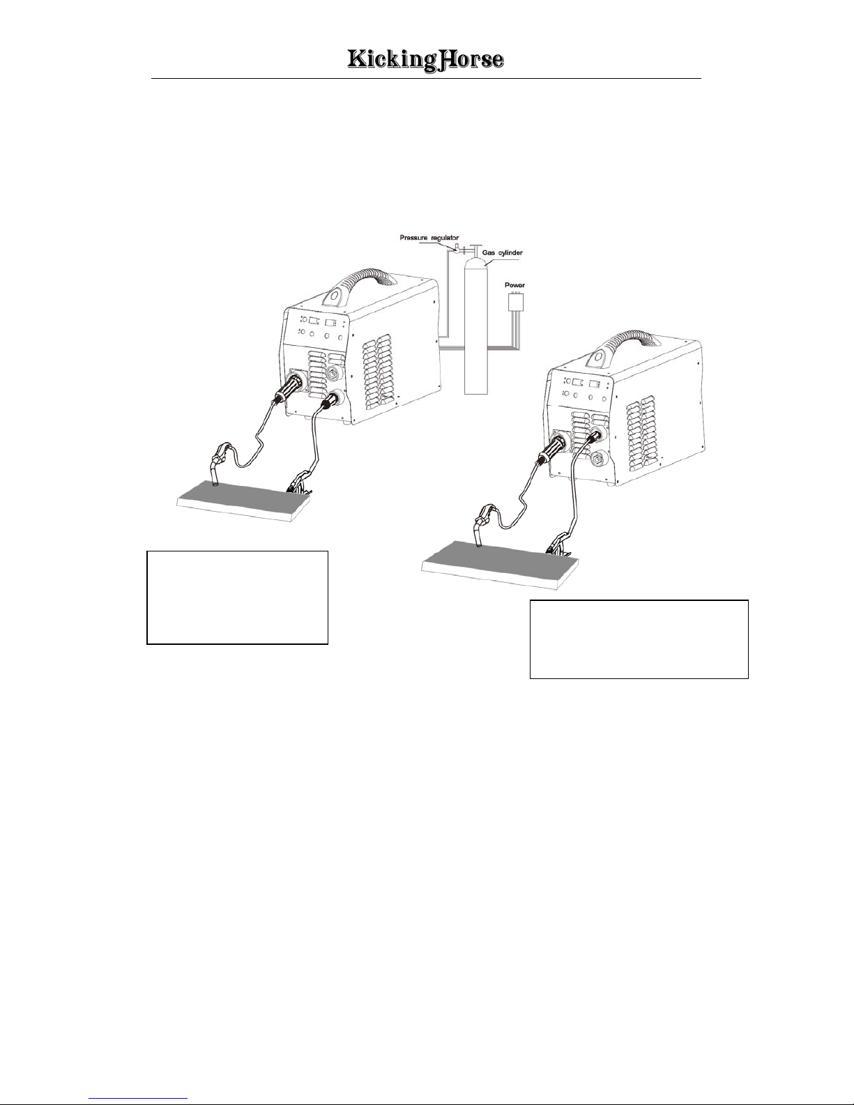
16. MIG Gun Polarity Lead: in MIG mode, connection positive output (+) is DCEP.
Connect to negative output (-) is DCEN. (see installation diagram).
5. Installation & Operation
The equipment protection level is IP23. Do not use in the rain!
The equipment must be turn off during installation!

MA200TS Multi-process welder 8 | Page
MIG welding installation diagram
DCEP for steel, stainless
steel and aluminum wire.
MIG Gun Polarity Lead
must connect to positive
output (+)
DCEN for flux cored wire.
MIG Gun Polarity Lead must
connect to negtive output (-)

MA200TS Multi-process welder 9 | Page
Stick welding installation diagram
TIG welding (scratch start) installation diagram
DCEP DCEN

MA200TS Multi-process welder 10 | Page
5.1. Electric service guide
Input voltage(V) 208 230
Frequency(Hz) 60 60
Input Amperes at rated output(A) 37 34
Max recommended standard fuse Rating in Amp
Circuit breaker, time delay
Normal operation
40
50
40
50
Min input conductor size in AWG 14 14
Min Grounding conductor Size in AWG 10 10
5.2. Installation
Welding machine should be installed in a stable position and with good ventilation.
Avoid direct sun outdoors or rain. Place at a distance of 12” (300mm) or more from
walls or similar that could restrict natural air flow for cooling. Avoid transport in
invert or side position.
Tightly connect the power cable to electrical socket outlet (refer to “technology
parameters” for the input voltage)
connect the compress air hose to the air supply equipment and the earth cable to the
workpiece.
Switch the ON/OFF Switch (located on the rear panel) to OFF.
Connect NT1 MIG torch euro connection and earth cable to negative connection.
Connect the control plug to the control receptacle at machine.
Connect the gas to the gas inlet locate on rear penal.
Install wire spool.
Commission the machine after the machine is installed and tested:
Release the pressure roller in the wire feeder, press the torch switch, and adjust voltage
switch from low to high, Open circuit voltage should rise.
Evenly adjust the current knob, the wire feed speed should increase evenly.
Check the connection of work piece, earth cable, welding torch, gas cylinder, regulator and
hose, make sure they are firm and reliable. Attach earth clamp as close as possible to the
cutting portion. Do not attach earth cable to the portion that will fall away.

MA200TS Multi-process welder 11 | Page
5.3. Recommended welding parameters
Note: The following table applies to low-carbon steel, other materials, please refer to related
information.
6. Safety precaution
6.1. Installation precaution
(1) Welding environmental temperature should be between -10Ԩ to 40Ԩ.
(2) The air humidity of not more than 90%.
(3) Avoid environment containing dust or corrosive gas.
(4) Avoid sunlight or rain; do not let water into the welding machine.
(5) Avoid the strong wind environment.

MA200TS Multi-process welder 12 | Page
6.2. Safety
Refer to the American National Standard Z49.1 entitled: SAFETY IN WELDING AND CUTTING.
ALL INSTALLATION, OPERATION, MAINTENANCE, AND REPAIR WORK MUST BE
PERFORMED BY QUALIFIED PERSONAL.
(1) Welders must be equipped with welding mask, gloves and tie the sleeves and collar properly.
Use Table 6.4 to choose proper glass shade, also can reference to ANSI Z49.1 listed in Safety
Standards. There should be an arc shield around welding field to protect others from arc shock.
(2) Do not weld near flammable, explosive materials or gases.
(3) Keep finger, hair and clothing away from the rotating fan.
(4) The power source must be grounded when welding.
(5) When protection light is enlightened during welding, it is indicating that the welder is over
current or over heat, and automatic protection will be triggered. Stop welding immediately and
wait until welder cool down.
(6) Welding machine should not work in a flammable and toxic environment, avoid moisture, rain,
and do not directly expose to sun.
(7) Do not switch off the welder during welding!
(8) Periodically maintain the machine and clean the dust inside.
7. Maintenance
Periodic maintenance is necessary for keeping the machine work properly.
WARNING
There are extremely dangerous voltage and power levels present inside this unit. Do not attempt
to diagnose or repair unless you have had training in power electronics measurement and
troubleshooting techniques. DISCONNECT POWER INPUT AND SWITCH OFF THE MAIN
POWER SWITCH BEFORE START OF MAINTENANCE.
Regular Check and Inspection 6 Month Routine Maintenance
Replace unreadable labels.
Clean spatter inside the nozzle when continuously
use the machine
Check and change broken parts in the torch to
Blow out with dry clean pressure air or vacuum
inside machine, especially transformer coil and
power component.
Check the electric connection of input/output bar
to avoid bad contact caused by loose or rusted

MA200TS Multi-process welder 13 | Page
avoid damage to the torch and machine.
Check the function of all switches.
Check if the fan rotates properly and if there is air
venting out from back of the machine.
Pay Attention to the abnormal vibration, noise,
smell and gas leakage during operation.
Check if the welding cables are over heated.
Check if the cable connections are over heated.
Check if the cable is connected firmly and
properly, if it is broken and cause bad insulation.
Check the cover grounded properly.
screw.
Check the contactors and relays in the machine or
on the PCB work properly.
Calibrate the current meter.
Check the resistance between machine case and
main circuit, if the value is smaller than 1MΩ,
sent the machine to an authorized warranty depot
to inspect and repair immediately.
8. Troubleshooting & Service
The following operations require the operator has sufficient electrical expertise and
comprehensive safety knowledge, the operator can demonstrate its capacity to be held valid
qualifications and knowledge Documents.
Common Faults and exclusion method:
NO. Troubles Reasons Solution
1 Close the breaker, but the
power light isn’t on
Breaker damaged Change it
Fuse damaged Change it
Power damaged Change it
2
After welding machine is
over-heat, the fan doesn’t
work
Fan damaged Change it
The cable is loosen Screw the cable tightly
3
Press the
gun switch,
no output
shielded gas
No output
gas when test
gas
No gas in the gas cylinder Change it
Gas pipe leaks gas Change it
Electromagnetic valve
damaged Change it
Output gas Control switch damaged Repair the switch

MA200TS Multi-process welder 14 | Page
when test gas Control circuit damaged Check the board
4
Wire-feeder
doesn’t
work
Wire reel
doesn’t work
Motor damaged Check and change it
Control circuit damaged Check the board
Wire reel
works
The press wheel is loosen or
weld wire skids Press it tightly again
The wheel doesn’t fit with
the diameter of weld wire Change the wheel
Wire reel damaged Change it
Wire feed pipe is jammed Repair or change it
Tip is jammed because of
splash Repair or change it
5 No striking arc and no
output voltage
Output cable is connected
mistakenly, or loosen Screw it down or change it
Control circuit damaged Check the circuit
6 Welding stops, and alarm
light is on Machine has self-protection
Check over-voltage, over-current,
over-temperature, lower-voltage and
over-temperature, and solve it
7 Welding current is run away
and can be not controlled
The potentiometer damaged Check or change it
The control circuit
damaged Check the circuit
8 The crater current can be not
adjusted The PCB damaged Check it
9 No post-gas The PCB damaged Check it

MA200TS multi-process welder 15 | Page
9. Torch Part Breakdown
KickingHorse™ NT1-3E, Order No. KAM31003
Nozzles
Item Description Order No.
1 Nozzle Self Insulated 21-37 A
2 Nozzle Self Insulated 21-50* A
3 Nozzle Self Insulated 21-62 A
4 Nozzle Self Insulated 21-37F A
5 Nozzle Self Insulated 21-50F A
6 Nozzle Self Insulated 21-62F A
7 Nozzle Self Shielding LA8201 B
Contact Tips

MA200TS Multi-process welder 16 | Page
Item Description Order No.
1 Contact Tip 0.023”/0.6mm Ecu 11-23 C
2 Contact Tip 0.030”/0.8mm Ecu 11-30 C
3 Contact Tip 0.035”/0.9mm Ecu 11-35* C
4 Contact Tip 0.040”/1.0mm Ecu 11-40 C
5 Contact Tip 0.045”/1.2mm Ecu 11-45 C
Liners
ITEM DESCRIPTION ORDER NO.
1 Steel Liner 0.030”-0.035”/0.8-0.9mm X15ft 42-3035-15* D
2 Teflon Liner 0.035”-0.045”/0.9-1.2mm X15ft 42T-3545-15 D
* Default
Component
ITEM DESCRIPTION PART No.
1 Gas Diffuser 51
2 Goose neck(45 ) 61-45
Goose neck(55 ) 61-55
3 Handle locking Nut EH1111
4 Gun Handle (Front) EH1101
5 Trigger Assembly EJ0003
6 Gun &Cable Assembly 3M TEL1030
7 Rear spring cable support ES2201
8 Gun plug housing EH2201
9 Screw(M4X6) EH2211
10 Rear lock nut EP2001
11 Euro connector(Tweco) ETU001
12 O ring 4x1 Q504010
13 O ring 4x8 Q504018
14 Nut M11X1 TEU1011

MA200TS Multi-process welder 17 | Page
NOTES
MA200TS MIG/Stick multi-process welder

MA200TS multi-process welder 18 | Page
NOTES
MA200TS MIG/Stick multi-process welder
Table of contents
Other KICKING HORSE Welding System manuals
Popular Welding System manuals by other brands

Lincoln Electric
Lincoln Electric STT-10 HEAD & CONTROLS BOOM MOUNT OR BENCH MODELS... Operator's manual

joke
joke ENESKAlaser 1500 mobile user manual

EWM
EWM Pico 162 VRD operating instructions

Cebora
Cebora DC 3241/T instruction manual

voestalpine
voestalpine Bohler URANOS 2000 SMC instruction manual

EINHELL
EINHELL CEN 160/1F operating instructions

SAF
SAF SAFEX M 253 Safety instruction for use and maintenance

Scheppach
Scheppach WSE1100 Translation of original instruction manual

GF Piping Systems
GF Piping Systems ECOS 160 instruction manual

Miller Electric
Miller Electric CST 280 Specifications

Sweiss
Sweiss PURE WELDING SKYCUT Series manual

Urrea
Urrea CP1040-BV User manual and warranty