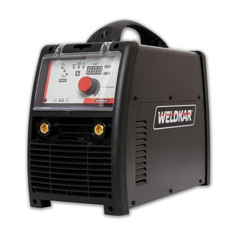
WELDKAR WK MIG 2125 User manual

www.weldkar.com
INVERTER WELDER
WK MIG 2125
welding
equipment
NED pag. 2
ENG page 11
DEU Seite 20
FRA page 30
GEBRUIKSAANWIJZING / INSTRUCTION MANUAL
BEDIENUNGSHANDBUCH / MODE D’EMPLOI

INVERTER WELDER WK MIG 2125
2
WAARSCHUWING
BESCHERM UZELF EN ANDEREN TEGEN MOGELIJK ERNSTIG LETSEL OF DE DOOD. HOUD
KINDEREN UIT DE BUURT. DRAGERS VAN PACEMAKERS MOETEN EEN GEPASTE AFSTAND IN ACHT
NEMEN TOT ZIJ MET EEN ARTS HEBBEN GESPROKEN. ZORG ERVOOR DAT DE HANDLEIDING NIET
ZOEK RAAKT. LEES DE GEBRUIKSAANWIJZING / HANDLEIDING VOORDAT U DE APPARATUUR
INSTALLEERT, GEBRUIKT OF ONDERHOUDT.
Indien de bediener zich niet strikt aan de veiligheidsvoorschriften houdt en geen voorzorgsmaatregelen neemt kunnen
lasproducten en -processen ernstig letsel of de dood veroorzaken of andere apparatuur of zaken beschadigen .
Aan de hand van ervaringen uit het verleden met het lassen en snijden zijn veilige werkmethoden ontwikkeld.
Deze methoden moeten door studie en training worden geleerd vóór het gebruik van deze apparatuur. Sommige van deze
methoden hebben betrekking op apparatuur die is aangesloten op voedingsleidingen; andere zijn van toepassing op door
motoren aangedreven apparatuur. Personen zonder uitgebreide opleiding in las- en snij methoden moeten niet proberen te
lassen.
De veilige werkmethoden staan uiteengezet in de Europese standaard EN 60974-1,
getiteld: Gezondheid en veiligheid bij het lassen en verwante processen – Deel 2: Elektrisch.
ALLE INSTALLATIE-, BEDIENINGS-, ONDERHOUDS- EN REPARATIEWERKZAAMHEDEN
MOGEN ALLEEN DOOR GEKWALIFICEERDE PERSONEN WORDEN UITGEVOERD.
Hoewel de informatie in deze handleiding het beste oordeel van de fabrikant weerspiegelt zal deze laatste geen
verantwoordelijkheid voor het gebruik ervan aanvaarden.
De gehele of gedeeltelijke reproductie van dit werk zonder voorafgaande schriftelijke toestemming van de uitgever is
verboden.
De uitgever aanvaardt geen, en verwerpt bij dezen elke aansprakelijkheid jegens enige partij voor alle verlies of schade
veroorzaakt door een fout of omissie in deze handleiding, ongeacht of deze fout het gevolg is van nalatigheid, een ongeluk
of andere oorzaken.
Alle rechten voorbehouden.
Copyright 2016
Weldkar Welding Equipment
www.weldkar.com
INHOUDSOPGAVE - NEDERLANDS
1 Veiligheidsinstructies en waarschuwingen 3
1.1 Gevaren verbonden aan het booglassen 3
1.2 Overzicht van de symbolen 6
2 Introductie 7
2.1 Algemene beschrijving 7
2.2 Technische specificaties 7
2.3 Verklaring van de op de kenplaat vermelde technische specificaties 7
2.4 Thermische beveiliging 7
2.5 Motoraangedreven generatoren 7
3 Installatie 8
3.1 Beschrijving van de uitrusting 8
3.2 Het monteren van de draadspoel 8
3.3 Draadaanvoer 8
3.4 Gasaansluiting 8
3.5 Lassen normaal staal 9
3.5.1 MIG-lassen met gasbescherming 9
3.5.2 MIG-lassen zonder gasbescherming 9
3.5.3 Aluminium MIG-lassen 9
3.5.4 RVS MIG-lassen 9
4 Service 10
4.1 De lasinverter onderhouden 10
4.2 Handelingen die u na een reparatie moet verrichten 10
4.3 Probleemoplossing en serviceverlening 10
A Elektrisch schema 41
B Onderdelentekening 42
!

3
1. VEILIGHEIDSINSTRUCTIES EN
WAARSCHUWINGEN
1.1GEVAREN VERBONDEN AAN
HET BOOGLASSEN
WAARSCHUWING
ELEKTRISCHE SCHOKKEN
kunnen dodelijk zijn.
Het aanraken van onder spanning staande elektrische
onderdelen kan tot fatale schokken of ernstige
brandwonden leiden. De elektrode en het elektrische
circuit staan altijd onder spanning wanneer de uitgang
is ingeschakeld. Het circuit van de voedingsspanning
en de interne circuits van de machine staan eveneens
onder spanning wanneer de stroom is ingeschakeld. Bij
halfautomatisch of automatisch lassen met lasdraad
staan de draad, spoel, aandrijfrol behuizing en alle
metalen onderdelen die de lasdraad raken, onder
spanning.
1. Raak geen onderdelen aan die onder spanning
staan.
2. Draag droge, isolerende handschoenen zonder
gaten en een lichaamsbescherming.
3. Isoleer uzelf van het werkstuk en de grond met
droge, isolerende matten of afdekkingen.
4. Koppel de stroombron los of stop de motor voordat
u deze apparatuur installeert of onderhoudt.
Vergrendel de hoofd voedingsschakelaar in de
open stand of verwijder de hoofdzekeringen om te
voorkomen dat de spanning per ongeluk kan worden
ingeschakeld.
5. Installeer en aard deze apparatuur volgens
de gebruikershandleiding en de landelijke en
plaatselijke voorschriften.
6. Schakel alle apparatuur UIT wanneer deze niet in
gebruik is. Schakel de stroom naar de apparatuur uit
als deze onbeheerd wordt gelaten of buiten dienst
wordt gesteld.
7. Gebruik volledig geïsoleerde elektrodehouders.
Steek de houder nooit in water om hem af te koelen
en leg hem nooit op de grond of het werkvlak. Raak
nooit tegelijkertijd elektrodehouders aan die zijn
verbonden aan twee lasmachines en raak geen
andere mensen met de houder of de elektrode.
8. Gebruik geen versleten, beschadigde, ondermaatse,
of slecht verbonden kabels.
9. Wikkel de kabels niet om het lichaam.
10. Aard het werkstuk voor een goede elektrische
aarding.
11. Raak de elektrode niet aan terwijl hij in contact is
met het werkcircuit (aardingsketen).
12. Gebruik alleen goed onderhouden apparatuur.
Repareer of vervang beschadigde onderdelen
onmiddellijk.
13. Gebruik in gesloten of vochtige ruimten geen
lasapparaat met een AC-uitgang tenzij hij is
uitgerust met een spanningsreductie apparaat.
Gebruik apparatuur met een DC-uitgang.
14. Draag een veiligheidsharnas om vallen te voorkomen
bij het werken boven het vloerniveau.
15. Houd alle panelen en afdekkingen goed op hun
plaats.
WAARSCHUWING
BOOGSTRALEN kunnen de ogen en
de huid verbranden; LAWAAI kan het
gehoor beschadigen.
Boogstralen van het lasproces produceren intense hitte
en krachtige ultraviolette stralen die de ogen en de huid
kunnen verbranden. Lawaai van sommige processen kan
het gehoor beschadigen.
1. Draag een lashelm voorzien van de juiste filtertint
om tijdens het lassen of het kijken uw gezicht en
ogen te beschermen.
2. Draag een goedgekeurde veiligheidsbril. Zijkapjes
worden aanbevolen.
3. Gebruik beschermende afschermingen of barrières
om anderen te beschermen tegen het flitsen en
schitteren; waarschuw anderen dat ze niet in de
boog moeten kijken.
4. Draag beschermende kleding gemaakt van
duurzaam, moeilijk ontvlambaar materiaal (wol en
leer) en voetbescherming.
5. Gebruik goedgekeurde oordopjes of oorbeschermers
als het geluidsniveau hoog is.
6. Draag tijdens het lassen nooit contactlenzen.
WAARSCHUWING
DAMPEN EN GASSEN
kunnen uw gezondheid schaden.
Bij het lassen komen dampen en gassen vrij. Het
inademen van deze dampen en gassen kunnen uw
gezondheid schaden.
1. Houd uw hoofd uit de dampen. Adem de dampen
niet in.
2. Indien u binnen werkt moet u de ruimte goed
ventileren en/of een afzuigkoker bij de boog
gebruiken om de lasrook en -gassen te verwijderen.
3. Bij een slechte ventilatie moet u een goedgekeurd
ademhalingstoestel met luchttoevoer gebruiken.
4. Lees de veiligheidsinformatiebladen en de
aanwijzingen van de fabrikant voor metalen,
verbruiksgoederen, coatings en reinigingsmiddelen.
5. Werk alleen in een gesloten ruimte als die goed is
geventileerd, of wanneer u een ademhalingstoestel
met luchttoevoer gebruikt. De bij het lassen
gebruikte schermgassen kunnen de lucht
verplaatsen en letsel of de dood veroorzaken. Zorg
ervoor dat de lucht voor het ademen veilig is.
6. Las niet op plaatsen in de buurt waarvan
ontvettings-,reinigings- of spuitwerkzaamheden
plaatsvinden. De hitte en stralen van de boog
kunnen met dampen reageren om zeer giftige en
irriterende gassen te vormen.
7. Las niet op gecoate metalen zoals gegalvaniseerd
staal of staal bekleed met lood of cadmium, tenzij
de coating is verwijderd van het lasgebied, de
ruimte goed is geventileerd en, indien nodig, u
een ademhalingstoestel met luchttoevoer draagt.
De coatings en alle metalen die deze elementen
bevatten kunnen giftige dampen afgeven tijdens het
lassen.
!
!
!
engdeufra ned

INVERTER WELDER WK MIG 2125
4
WAARSCHUWING
Lassen kan leiden tot BRAND of
EXPLOSIES.
Vonken en spatten vliegen van de
lasboog.
De rondvliegende vonken en hete stukjes metaal, de
lasspatten, het hete werkstuk en de hete apparatuur
kunnen brand en brandwonden veroorzaken. Een
toevallig contact van de elektrode of lasdraad
met metalen voorwerpen kan leiden tot vonken,
oververhitting of brand.
1. Bescherm uzelf en anderen tegen rondvliegende
vonken en stukjes heet metaal.
2. Las niet op plaatsen waar rondvliegende vonken
brandbare materialen kunnen treffen.
3. Verwijder alle brandbare materialen binnen een
straal van ongeveer 11 m van de lasboog, als dit
niet mogelijk is moet u ze goed afdekken met
goedgekeurde afdekkingen.
4. Let ervoor op dat vonken en hete materialen
afkomstig van het lassen gemakkelijk door kleine
scheurtjes en openingen naar aangrenzende
gebieden kunnen overvliegen.
5. Let op voor brand en houd een brandblusser in de
buurt.
6. Wees ervan bewust dat het lassen tegen een
plafond, op een vloer, schot of scheidingswand
brand aan de verborgen kant kan veroorzaken.
7. Las niet op gesloten containers zoals tanks of vaten.
8. Sluit de kabel zo dicht mogelijk in de buurt van het
lasgebied als praktisch is aan op het werkstuk om
de baan van de lasstroom zo kort mogelijk te houden
en mogelijk onbekende trajecten en het veroorzaken
van elektrische schokken en brand te voorkomen.
9. Gebruik een lasapparaat niet om bevroren leidingen
mee te ontdooien.
10. Verwijder de staafelektrode uit de houder of snij de
lasdraad af bij het contactmondstuk wanneer het
apparaat niet wordt gebruikt.
WAARSCHUWING
RONDVLIEGENDE VONKEN EN
STUKJES HEET METAAL kunnen letsel
veroorzaken.
Bij het verspanen en slijpen komen rondvliegende
stukjes metaal vrij. Afkoelende lassen kunnen slakken
afwerpen.
1. Draag een goedgekeurde laskap of veiligheidsbril.
Zijkapjes worden aanbevolen.
2 Draag een goede lichaamsbescherming om de huid
te beschermen.
WAARSCHUWING
Indien beschadigd kunnen
GASFLESSEN ontploffen.
Schermgasflessen bevatten gas onder hoge druk.
Indien beschadigd zal een gasfles kunnen exploderen.
Aangezien gasflessen normaal gesproken deel uitmaken
van het lasproces, moet u ze zorgvuldig behandelen.
1. Bescherm persgasflessen tegen overmatige hitte,
mechanische schokken en lasbogen.
2. Blokkeer de gasfles in verticale stand met een
ketting aan een vaste steun of het flessenrek van
de apparatuur om het vallen of kantelen ervan te
voorkomen.
3. Houd gasflessen uit de buurt van alle las- of andere
elektrische circuits.
4. Een laselektrode mag nooit een gasfles aanraken.
5. Gebruik alleen de juiste beschermgasflessen,
-regelaars, -slangen en -hulpstukken die moeten zijn
ontworpen voor het specifieke gebruik ervan; zorg
ervoor dat die en de bijbehorende onderdelen ervan
in goede staat blijven.
6. Draai bij het openen van de gasfleskraan het gezicht
weg van de uitgang van de kraan.
7. Laat de beschermkap altijd op zijn plaats over de
kraan, behalve tijdens het gebruik van de gasfles of
de aansluiting ervan voor gebruik.
8. Lees en houdt u zich aan de instructies over flessen
met samengeperst gas, de bijbehorende apparatuur
die in de veiligheidsnormen staat vermeld.
WAARSCHUWING
BEWEGENDE DELEN
kunnen letsel veroorzaken
Bewegende delen, zoals ventilatoren, rotoren en snaren
kunnen vingers en handen afsnijden en fladderende
kleding vastgrijpen.
1. Houd alle deuren, panelen, deksels en
beschermkappen gesloten en veilig op hun plaats.
2. Stop de motor voordat u het apparaat installeert of
aansluit.
3. Indien noodzakelijk mogen alleen bevoegde
personen beschermkappen of afdekkingen
verwijderen voor het onderhoud en het oplossen van
problemen.
4. Om het ongewenste starten tijdens het onderhoud
te voorkomen moet u de negatieve (-) accukabel van
de accu loskoppelen.
5. Houd handen, haar, fladderende kleding en
gereedschap uit de buurt van de bewegende delen.
6. Installeer de panelen of beschermkappen weer
terug en sluit de deuren wanneer het onderhoud is
voltooid en voordat u de motor start.
!
!
!
!

5
WAARSCHUWING
VONKEN kunnen ACCUGASSEN laten
ONTPLOFFEN; ACCUZUUR kan de
ogen en de huid verbranden.
Accu’s bevatten zuur en genereren explosieve gassen.
1. Draag altijd een gezichtsbescherming wanneer u
aan een batterij werkt.
2. Stop de motor voordat u de accukabels loskoppelt
of aansluit.
3. Zorg ervoor dat het gereedschap geen vonken
creëert wanneer u aan een accu werkt.
4. Gebruik het lasapparaat niet om accu’s mee op te
laden of om voertuigen mee te starten.
5. Let op de juiste polariteit (+ en -) op de accu’s.
OPMERKING
Overwegingen over lassen en de effecten van
laagfrequente elektrische en magnetische velden
De elektrische stroom die door een willekeurige
conductor stroomt produceert elektromagnetische
velden (EMF). De las- of snijstroom produceert
elektromagnetische velden rondom de kabels en de
generatoren.
De magnetische velden geproduceerd door hoge stroom
kunnen de functionering van pacemakers beïnvloeden.
De dragers van vitale elektronische apparatuur
(pacemakers) moeten zich tot hun arts wenden voordat
ze booglas-, snij, afbrand- of puntlas werkzaamheden
benaderen.
De blootstelling aan elektromagnetische velden,
geproduceerd tijdens het lassen of snijden, kunnen de
gezondheid op onbekende manier beïnvloeden.
Om magnetische velden op de werkplek te beperken
moet u de volgende procedures opvolgen.
1. Houd kabels dicht bij elkaar door ze te verdraaien
2. Houd de kabel aan één kant en uit de buurt van de
gebruiker.
3. Rol of hang geen kabels rondom het lichaam.
4. Houd de lasstroombron en -kabels zo ver mogelijk
van het lichaam als praktisch is.
WAARSCHUWING
OVER PACEMAKERS
De bovenstaande procedures vallen onder die welke
normaalgesproken worden aanbevolen voor dragers van
een pacemaker.Raadpleeg uw arts voor meer informatie.
!
!
engdeufra ned

INVERTER WELDER WK MIG 2125
6
Wolfraam booglassen
met gas (GTAW)
Constante stroom
Hoge temperatuur
Foutmelding
Lasboogkracht
Starten door aanraken
(GTAW)
Variabele inductantie
Ingangsspanning
Eenfase
Driefasen
Gevaarlijke spanning
AAN
UIT
Bedieningspaneel/
plaatselijk
Booglassen met metaal
in atmosfeer van inert
gas (GMAW)
Omhoog/omlaag
Vermogensschakelaar
Remote
Bedrijfscyclus
Percentage
Stroomsterkte
Spanning
Hertz (cycli/sec)
Frequentie
Negatief
Positief
Gelijkstroom (DC)
Beschermende aarde
(aarde)
Lijn
Lijnaansluiting
Hulpvermogen
Classificering contactdoos
hulpvermogen
115V 15A
t
t1
t2
%
X
IPM
MPM
t
V
Zekering
Draadaanvoerfunctie
Voorstroomtijd
Nastroomtijd
Puntlastijd
Puntlasmodus
Indrukken om de draadtoevoer en
het lassen te starten; loslaten om
te stoppen.
Doorblazen van gas
Inches per minuut
Meter per minuut
Laspistool
Burnback-tijd
2-Staps-
trekkerbediening
Zie opmerking
Zie opmerking
Pulserend lassen
AC-hulpvermogen
Driefasen statische
frequentieomvormer -
Transformator-gelijkrichter
Snijden met
koolelektrode en
perslucht (CAC-A)
Booglassen met
beklede elektrode
(SMAW)
Continue
lasmodus
Draadaanvoer naar
werkstuk met uitgangs-
spanning UIT (OFF)
Constante spanning of
constant potentiaal
1.2 OVERZICHT VAN DE SYMBOLEN
Merk op dat slechts enkele van deze symbolen op uw model zullen voorkomen.

7
2. INTRODUCTIE
2.1ALGEMENE BESCHRIJVING
WELDKAR MIG 2125
De Weldkar WK MIG 2125 is een krachtige MIG
inverter op 230 Volt. Deze kleinste telg uit het Weldkar
MIG programma blinkt uit in laskwaliteit, compactheid
en eenvoud. Met een gewicht van slechts 12,5 kg
is deze draagbare, robuuste machine de ideale
lashulp voor zowel in de werkplaats als op locatie.
Met een netspanning van 230 Volt en een maximaal
lasvermogen van 200 Ampère, heeft men een groot
toepassingsgebied op staal en CuSi3.
De machine is traploos regelbaar, voorzien van burn-
back schakelaar, “wave control” (zorgt voor een rustige,
afgevlakte lasboog in het kortsluitboog gebied) en
centraal aansluiting. De sterke, uit aluminium gegoten
2-rols draadaanvoerunit transporteert het lasdraad
probleemloos over een lengte van maximaal 4 meter. De
machine is voorzien van CE en EMC en is geschikt voor
gebruik op aggregaten met voldoende vermogen.
Lasinverter wordt standaard geleverd met een:
- WK MIG 2125 Inverter Stroombron
- Aardklem met 4 meter massakabel en Din. Stekker
- Mig-Lastoorts WK 150 - 3 meter
- Voedingskabel 5 meter, 3 x 2.5 mm
2
- Gasslang
- Aluminium Draad-aanvoermotor 2-rols
- Bedieningshandleiding
In de onderstaande instructies vindt u gedetailleerde
informatie voor een correct en veilig gebruik van de
machine en aanwijzingen om de hoogste efficiëntie en
kwaliteit uit uw stroombron te halen.
GEBRUIK HET APPARAAT NIET VOOR HET
ONTDOOIEN VAN BUIZEN.
2.2 TECHNISCHE SPECIFICATIES
Model WK MIG 2125
Netspanning 1-fase 230 Volt / ± 10%
Frequentie 50 / 60 Hz
Afzekering 16 A (traag)
Lasstroombereik 50 – 200 A
Inschakelduur (40°C - 10 min.) 200 A – 25%
120 A – 100%
Nullastspanning 42 Volt
Te verlassen draad FE: 0,6/0,8/1,0
INOX: 0,8/1,0
CuSi3: 0,8
Gevuld: 0,9
Max. draadspoeldiameter Ø 200 mm / 5 kg
Aandrijving 2-rols
Beschermingsklasse IP 23
Isolatieklasse H
Gewicht 12,5 kg
Afmetingen (LxBxH) 465 x 214 x 395 mm
2.3 VERKLARING VAN DE OP DE KENPLAAT
VERMELDE TECHNISCHE SPECIFICATIES.
Het apparaat is gebouwd in overeenstemming met de
volgende normen: IEC 60974.1
N° Serienummer, dat moet worden vermeld
bij elk verzoek betreffende de lasmachine.
Statische monofase frequentie converter
transformator-gelijkrichter.
Geschikt voor MIG/MAG lassen.
Dalende karakteristiek.
U
0
Secundaire nullast spanning.
X Werkcyclus percentage. Percentage
van 10 minuten gedurende dewelke de
lasmachine kan werken met een bepaalde
stroom zonder te oververhitten.
I
2
Lasstroom.
U
2
Secundaire spanning bij lasstroom I
2
.
U
1
Nominale toevoerspanning.
I
1max
Dit is de maximumwaarde van de
opgenomen stroom.
I
1eff
Dit is de maximumwaarde van de werkelijk
opgenomen stroom, afhankelijk van de
inschakelduur.
IP23 Beschermingsgraad van de kast. De
Graad 3 als tweede cijfer geeft
aan dat het apparaat opgeslagen kan
worden, maar dat het bij neerslag niet
buiten gebruikt kan worden,
tenzij in een beschermde omgeving.
Geschikt voor gevaarlijke omgevingen.
H Isolatieklasse.
AF Luchtkoeling met ventilator.
2.4 THERMISCHE BEVEILIGING
Deze Inverter is beveiligd door een thermostaat.
Wanneer de thermostaat in werking treedt, levert de
machine geen stroom meer, maar blijft de ventilator
werken. Het gele led-lampje (9) licht op om aan te
geven dat de thermostaat is geactiveerd. Schakel de
lasmachine niet uit voordat het led-lampje is gedoofd.
2.5 MOTORAANGEDREVEN GENERATOREN
Deze moeten een vermogen hebben van 6 KVA of meer
en mogen geen spanning leveren die hoger is dan 265 V.
engdeufra ned

INVERTER WELDER WK MIG 2125
8
3. INSTALLATIE
Lees deze instructies vóór het gebruik van het apparaat
a.u.b. aandachtig door.
Deze moet worden uitgevoerd door bevoegd
personeel. Alle aansluitingen moeten tot stand
worden gebracht overeenkomstig de geldende
voorschriften en in volledige overeenstemming met
de veiligheidsreglementen (CEI reglement 26-10 -
CENELEC HD 427).
- Vergewis u ervan dat de netspanning overeenstemt
met de spanning die is aangegeven op het
kenplaatje.
- Controleer bij het monteren van een stekker of
deze een geschikte capaciteit heeft en verbind de
geel/groene geleider van de voedingskabel met de
aardingspen.
WAARSCHUWING! Verlengkabels tot 30 m moeten een
doorsnede hebben van minstens 2,5 mm².
3.1 BESCHRIJVING VAN DE UITRUSTING
1) Mig-Lastoorts aansluiting
2) Din Massakabelaansluiting (-)
3) Aan / Uitschakelaar (hoofdschakelaar)
4) Gasslang aansluiting.
5) Voedingskabel
6) Ventilator voor het koelen van de omvormer.
7) Digitale display (Voltage).
8)
Led-lamp deze brandt als het apparaat is ingeschakeld.
9) Led-lamp om aan te geven dat de thermostaat is
geactiveerd.
10) Digitale display (Lasstroom, draadaanvoersnelheid)
11) Led-lamp die aangeeft dat het display (10)
de draadaanvoersnelheid voor het MIG-lassen
weergeeft.
12) Led-lamp die aangeeft dat het display (10) de
lasstroom weergeeft.
13) Keuzeschakelaar 2-takt of 4-takt.
14) Wave control: Zorgt voor een rustige, afgevlakte
lasboog in het kortsluitboog gebied.
15) Instelknop: Regelt, afhankelijk van de
geselecteerde LED, de lasstroom (LED 12) of
draadaanvoersnelheid bij MIG-lassen (LED 11).
16) Instelknop lasspanning: Gebruik deze om de
lasspanning in te stellen.
3.2 HET MONTEREN VAN DE DRAADSPOEL
1. Plaats de draadspoel van 5 kg op de draadrolhouder.
2. Stel de naafspanning in zodat de draadrol op de
juiste afstelling is ingesteld.
3. Gebruik de moer om de draadspoel vast te zetten.
3.3 DRAADAANVOER
Zorg ervoor dat de draaddiameter overeenkomt
met de draaddiameter groef in de aandrijfrol van de
aanvoermotor. Plaats de lasdraad op de draadrolhouder
en voer de draad (handmatig) tot in de aanvoerbuis
en verwijder op het laspistool de contactbuis en het
gasmondstuk. Door de machine aan te zetten en de
toortsschakelaar ingedrukt te houden kan men de
lasdraad doorvoeren tot deze uit de lastoorts komt,
daarna monteert men weer de contactbuis (let op dat de
lasdraaddiameter overeenkomt met de diameter van de
contactbuis) en het gasmondstuk.
3.4 GASAANSLUITING
- Bevestig de gascilinder met een ketting aan
de laswagen, de wand of een andere vaste
ondersteuning, zodat de cilinder niet kan vallen
en de kraan kan afbreken.
- Monteer het reduceerventiel op de gascilinder
en draai de moer met een sleutel vast, let op dat
er een afdichtring is gemonteerd.
- Bevestig de gasslang aan het reduceerventiel en
zet deze vast met een slangklem, dit om lekkage
te voorkomen.
- Open de gascilinder en stel de druk in op
8 - 10 ltr./min.
LET OP: Het gassoort moet overeenkomen met het
materiaal wat u wilt lassen.
4
3
1
26
5
Figuur 1
Figuur 3
Gascilinder
Reduceerventiel
Beschermgas
Lastoorts
Stroombron met
draadaanvoerunit
Aardklem
Werkstuk
7
9
8 10 11
12
13
141516
Figuur 2

9
3.5 LASSEN NORMAAL STAAL
3.5.1 MIG-LASSEN MET GASBESCHERMING
Voor het lassen van staal gebruikt men een gasmengsel
van 85% Argon en 15% CO-2 (menggas) ook andere
gasmengsels zijn mogelijk, zoals bv. (80%-20%).
- Sluit de massakabel aan op de Din-Aansluiting
(2). Sluit het kabeloog van de massakabel, in de
draadaanvoerunit, aan op de minpool.
- Sluit de Mig-Lastoorts aan op de aansluiting (1).
Sluit de voedingskabel van de MIG-Lastoorts aan op
de pluspool.
- Stel de lasspanning in met de keuzeknop (16)
- Plaats de MIG-Lastoorts op het materiaal en
druk de schakelaar op de lastoorts in en stel de
draadsnelheid zodanig in dat je een egaal en
gelijkmatig geluid krijgt.
Of zie de tabel voor de juiste instelling.
- Als de draadsnelheid te hoog is zal de draad geen
tijd krijgen om goed in te branden en zal er veel
spat- en vonkvorming zijn. Als de draadsnelheid
te laag is ingesteld zal de draad afsmelten in
druppelvorm en dus ook geen goede inbranding
geven.
- Als men de lasklus geklaard heeft en ermee wil
stoppen zet dan de machine (3) uit en sluit de
gascilinder af.
WK MIG 2125
Richtlijnen instelmogelijkheden
Plaatdikte in mm Meters per minuut Voltage
Staal SG-2 0,6mm
1,0mm 7,7m/min 14,5V
1,5mm 10,0m/min 17,5V
2,0mm 12,7m/min 18,9V
2,5mm 13,0m/min 21,0V
Staal SG-2 0,8mm
1,0mm 2,8m/min 14,5V
1,5mm 6,0m/min 17,0V
2,0mm 7,3m/min 18,0V
2,5mm 8,6m/min 18,8V
3,0mm 10.0m/min 19,5V
3,5mm 11,5m/min 22,0V
Staal SG-2 1,0mm
1,5mm 3,3m/min 16,2V
2,0mm 4,5m/min 16,4V
2,5mm 5,3m/min 18,0V
3,0mm 6,0m/min 18,5V
3,5mm 6,6m/min 19,2V
CuSi3 0,8mm
0,8mm 4,2m/min 13,3V
1,0mm 5,0m/min 13,4V
1,5mm 10,0m/min 14,8V
3.5.2 MIG-LASSEN ZONDER
GASBESCHERMING
De handelingen om het apparaat voor te bereiden voor
het lassen zijn dezelfde als hiervoor beschreven.
Voor dit type van lassen dient u echter als volgt te werk
te gaan:
- Monteer een spoel met gevulde draad voor lassen
zonder gas.
- Sluit de Mig-Lastoorts aan op de aansluiting (1).
Sluit de voedingskabel van de MIG-Lastoorts aan op
de minpool.
- Sluit de massakabel aan op de Din-aansluiting
(2). Sluit het kabeloog van de massakabel, in de
draadaanvoerunit, aan op de pluspool.
- Selecteer een programma dat geschikt is voor het
lassen met gevulde draad.
- Gebruik voor het lassen zonder gasbescherming bv,
de 0.9 mm gevulde flux lasdraad, die voldoet aan de
standaard AWS AS.20 E71.
- Plaats de aardkabel met massaklem op het
werkstuk.
N.B.Voor de juiste laspositie last men altijd van links
naar rechts (zie fig. 4).
3.5.3 ALUMINIUM MIG-LASSEN
Het lasapparaat wordt ingesteld zoals omschreven
in paragraaf 3.5.1. met de volgende verschillen, men
gebruikt nu 100% Argon als beschermingsgas.
- Gebruik ook een aluminium lasdraad b.v. ALMG-5
en draadaanvoerrollen die speciaal ontworpen zijn
voor aluminium lasdraad.
- Gebruik deze rollen niet voor staal of rvs lassen.
Werk schoon!
- De draadspoelen moeten in plastic zakken bewaard
worden met daarin absorptiekorrels.
- Zie voor de juiste laspositie fig. 4.
3.5.4 RVS MIG-LASSEN
Het lasapparaat wordt ingesteld zoals omschreven
in paragraaf 3.5.1 met de volgende verschillen, men
gebruikt nu 98% Argon en 2% O2 als beschermgas.
- Voor de keuze van het lasdraad kan men kiezen uit
RVS 304, 308 of 316 LSI
- Zie voor de aanbevolen laspositie fig. 4.
Figuur 4
engdeufra ned

INVERTER WELDER WK MIG 2125
10
4. SERVICE
ALLE ONDERHOUDS- EN
REPARATIEWERKZAAMHEDEN MOGEN
ALLEEN DOOR GEKWALIFICEERDE PERSONEN
WORDEN UITGEVOERD.
4.1DE LASINVERTER ONDERHOUDEN
Controleer of de schakelaar (3) op “O” staat en of de
voedingskabel van het lichtnet losgekoppeld is als u
onderhoud in het apparaat moet uitvoeren.
Reinig tevens regelmatig de binnenkant van het
apparaat en verwijder de opgehoopte metaalstof met
behulp van perslucht.
4.2 HANDELINGEN DIE U NA EEN REPARATIE
MOET VERRICHTEN
Controleer na een reparatie of de bekabeling correct
aangebracht is en of er sprake is van voldoende
isolatie tussen de primaire en secundaire zijde van de
machine. Zorg ervoor dat de draden niet in aanraking
kunnen komen met de onderdelen in beweging of de
onderdelen die tijdens de functionering verhit raken.
Hermonteer alle klemringen op de oorspronkelijke wijze
om een verbinding tussen de primaire en secundaire te
voorkomen als een draad breekt of losschiet.
Hermonteer tevens de schroeven met de tandringen op
de oorspronkelijke wijze.
Probleem Oorzaak
Door de motor in de kast aangedreven
draadaanvoerrol heeft geslipt. De draadhaspelrem is te zwaar afgesteld.
De draadhaspel is afgerold en het
draad is verstrikt geraakt. De draadhaspelrem is te licht afgesteld.
Versleten of verkeerde grootte van de
draadaanvoerrol. Gebruik een draadaanvoerrol die geschikt is voor de diameter die u last.
Vervang de draadaanvoerrol indien versleten.
Draad aangewreven tegen de slecht
uitgelijnde geleiders en de mogelijke
draadaanvoer is beperkt.
Verkeerde uitlijning van inlaat-/uitlaatgeleiders.
Aanvoer geblokkeerd door vervuiling. Wanneer teveel druk op de regelaar van de drukrol wordt uitgeoefend zullen
tijdens het doorvoeren van de lasdraad koper resten achterblijven.
Koperresten kunnen ook worden geproduceerd door de passage van de draad
door een verkeerde vorm of grootte van de groef van de draadaanvoerrol.
Koperresten komen in de voering (binnenspiraal) van de lastoorts terecht waar
ze ophopen en de mogelijk van aanvoer van de draad beperken.
Verkeerde of versleten contacttip. De contacttip brengt de lasstroom over op de lasdraad. Wanneer de diameter
van de contacttip niet overeenkomt met het te verlassen lasdraad, dan kan
boogvorming binnenin de contacttip plaatsvinden met als gevolg het vast
branden van de lasdraad in de conttacttip.
Zacht lasdraad zoals aluminium kan vast komen te zitten in de contacttip als
gevolg van het uitzetten van de draad door de verhitting ervan.
Slecht contact (massa) van de
aardklem met het werkstuk. Bij een slecht elektrisch contact tussen de aardklem en het werkstuk zal het
verbindingspunt verhit raken en zal het vermogen van de boog verminderen.
Verbogen voering/binnenspiraal. Dit zal leiden tot frictie tussen de draad en de voering en aldus de mogelijkheid
om de draad aan te voeren beperken.
4.3PROBLEEMOPLOSSING EN SERVICEVERLENING
Problemen bij onregelmatige draadaanvoer:
Draadaanvoerproblemen kunnen worden verminderd door een controle van de volgende punten:

11
INVERTER WELDER
WK MIG 2125
INSTRUCTION MANUAL
INSTRUCTION MANUAL
ENGLISH

INVERTER WELDER WK MIG 2125
12
INVERTER WELDER WK MIG 2125
WARNING
PROTECT YOURSELF AND OTHERS FROM POSSIBLE SERIOUS INJURY OR DEATH. KEEP CHILDREN
AWAY. PACEMAKER WEARERS KEEP AWAY UNTIL CONSULTING YOUR DOCTOR. DO NOT LOSE
THESE INSTRUCTIONS. READ OPERATING/INSTRUCTION MANUAL BEFORE INSTALLING,
OPERATING OR SERVICING THIS EQUIPMENT.
Welding products and welding processes can cause serious injury or death, or damage to other equipment or property, if
the operator does not strictly observe all safety rules and take precautionary actions.
Safe practices have developed from past experience in the use of welding and cutting. These practices must be learned
through study and training before using this equipment. Some of these practices apply to equipment connected to power
lines; other practices apply to engine driven equipment. Anyone not having extensive training in welding and cutting
practices should not attempt to weld.
Safe practices are outlined in the European Standard EN60974-1 entitled: Safety in welding and allied processes - Part 2:
Electrical. This publication and other guides to what you should learn before operating this equipment are listed at the end
of these safety precautions.
HAVE ALL INSTALLATION, OPERATION, MAINTENANCE, AND REPAIR WORK PERFORMED
ONLY BY QUALIFIED PEOPLE.
While the information contained in this Manual represents the Manufacturer’s best judgement, the Manufacturer assumes
no liability for its use.
Reproduction of this work, in whole or in part, without written permission of the publisher is prohibited.
The publisher does not assume and hereby disclaims any liability to any party for any loss or damage caused by any error
or omission in this Manual, whether such error results from negligence, accident, or any other cause.
All rights reserved.
Copyright 2016
Weldkar Welding Equipment
www.weldkar.com
!
12
TABLE OF CONTENTS - ENGLISH
1 Safety Instructions and Warnings 13
1.1 Arc Welding Hazards 13
1.2 Symbol Chart 15
2 Introduction 16
2.1 General description 16
2.2 Technical specifications 16
2.3 Explanation of the technical specifications listed on the machine plate 16
2.4 Thermal protection 16
2.5 Motor-driven generators 16
3 Installation 17
3.1 Description of the equipment 17
3.2 Reel fitting sequence 17
3.3 Wire feed 17
3.4 Gas connection 17
3.5 Welding mild steel 18
3.5.1 MIG Welding with gas protection 18
3.5.2 MIG Welding without gas protection 18
3.5.3 MIG Welding aluminium 18
3.5.4 MIG welding stainless steel 18
4 Maintenance 19
4.1 Maintenance of the welding inverter 19
4.2 Precautions after repairs 19
4.3 Troubleshooting & Service 19
A Electrical principle drawing 41
B Spare Parts list 42

1313
eng
deufra ned
1. SAFETY INSTRUCTIONS AND
WARNINGS
1.1ARC WELDING HAZARDS
WARNING
ELECTRIC SHOCK
can kill
Touching live electrical parts can cause fatal shocks
or severe burns. The electrode and work circuit is
electrically live whenever the output is on. The input
power circuit and machine internal circuits are also live
when power is on. In semi-automatic or automatic wire
welding, the wire, wire reel, drive roll housing, and all
metal parts touching the welding wire are electrically
live. Incorrectly installed or improperly grounded
equipment is a hazard.
1. Do not touch live electrical parts.
2. Wear dry, hole-free insulating gloves and body
protection.
3. Insulate yourself from work and ground using dry
insulating mats or covers.
4. Disconnect input power or stop engine before
installing or servicing this equipment. Lock input
power disconnect switch open, or remove line fuses
so power cannot be turned on accidentally.
5. Properly install and ground this equipment according
to its Owner’s Manual and national, state, and local
codes.
6. Turn OFF all equipment when not in use. Disconnect
power to equipment if it will be left unattended or
out of service.
7. Use fully insulated electrode holders. Never dip
holder in water to cool it or lay it down on the
ground or the work surface. Do not touch holders
connected to two welding machines at the same
time or touch other people with the holder or
electrode.
8. Do not use worn, damaged, undersized, or poorly
spliced cables.
9. Do not wrap cables around your body.
10. Ground the workpiece to a good electrical (earth)
ground.
11. Do not touch electrode while in contact with the
work (ground) circuit.
12. Use only well-maintained equipment. Repair or
replace damaged parts at once.
13. In confined spaces or damp locations, do not use a
welder with AC output unless it is equipped with a
voltage reducer. Use equipment with DC output
14. Wear a safety harness to prevent falling if working
above floor level.
15. Keep all panels and covers securely in place.
WARNING
ARC RAYS can burn eyes and skin;
NOISE can damage hearing.
Arc rays from the welding process produce intense heat
and strong ultraviolet rays that can burn eyes and skin.
Noise from some processes can damage hearing.
1. Wear a welding helmet fitted with a proper shade of
filter to protect your face and eyes when welding or
watching.
2. Wear approved safety glasses. Side shields
recommended.
3. Use protective screens or barriers to protect others
from flash and glare; warn others not to watch the
arc.
4. Wear protective clothing made from durable,
flame-resistant material (wool and leather) and foot
protection.
5. Use approved ear plugs or ear muffs if noise level is
high.
6. Never wear contact lenses while welding.
WARNING
FUMES AND GASES
can be hazardous to your health.
Welding produces fumes and gases.
Breathing these fumes and gases can be hazardous to
your health.
1. Keep your head out of the fumes. Do not breathe
the fumes.
2. If inside, ventilate the area and/or use exhaust at
the arc to remove welding fumes and gases.
3. If ventilation is poor, use an approved air-supplied
respirator.
4. Read the Material Safety Data Sheets (MSDSs)
and the manufacturer’s instruction for metals,
consumables, coatings, and cleaners.
5. Work in a confined space only if it is well ventilated,
or while wearing an air-supplied respirator. Shielding
gases used for welding can displace air causing
injury or death. Be sure the breathing air is safe.
6. Do not weld in locations near degreasing, cleaning,
or spraying operations. The heat and rays of the
arc can react with vapours to form highly toxic and
irritating gases.
7. Do not weld on coated metals, such as galvanized,
lead, or cadmium plated steel, unless the coating
is removed from the weld area, the area is well
ventilated, and if necessary, while wearing an
airsupplied respirator. The coatings and any metals
containing these elements can give off toxic fumes if
welded.
WARNING
Welding can cause FIRE or
EXPLOSION.
Sparks and spatter fly off from the
welding arc
The flying sparks and hot metal, weld spatter, hot
workpiece, and hot equipment can cause fires and
burns.
Accidental contact of electrode or welding wire to metal
objects can cause sparks, overheating, or fire
1. Protect yourself and others from flying sparks and
hot metal.
2 Do not weld where flying sparks can strike
flammable material.
3. Remove all flammables within 35 ft (11 m) of the
!
!
!
!

INVERTER WELDER WK MIG 2125
1414
welding arc. If this is not possible, tightly cover
them with approved covers.
4. Be alert that welding sparks and hot materials from
welding can easily go through small cracks and
openings to adjacent areas.
5. Watch for fire, and keep a fire extinguisher nearby.
6. Be aware that welding on a ceiling, floor, bulkhead,
or partition can cause fire on the hidden side.
7. Do not weld on closed containers such as tanks or
drums.
8. Connect work cable to the work as close to the
welding area as practical to prevent welding current
from travelling long, possibly unknown paths and
causing electric shock and fire hazards.
9. Do not use welder to thaw frozen pipes.
10. Remove stick electrode from holder or cut off
welding wire at contact tip when not in use.
WARNING
FLYING SPARKS AND HOT METAL
can cause injury.
Chipping and grinding cause flying metal.
As welds cool, they can throw off slag.
1. Wear approved face shield or safety goggles. Side
shields recommended.
2. Wear proper body protection to protect skin.
WARNING
CYLINDERS can explode
if damaged.
Shielding gas cylinders contain gas under high pressure.
If damaged, a cylinder can explode. Since gas cylinders
are normally part of the welding process, be sure to
treat them carefully.
1. Protect compressed gas cylinders from excessive
heat, mechanical shocks, and arcs.
2. Install and secure cylinders in an upright position by
chaining them to a stationary support or equipment
cylinder rack to prevent falling or tipping.
3. Keep cylinders away from any welding or other
electrical circuits.
4. Never allow a welding electrode to touch any
cylinder.
5. Use only correct shielding gas cylinders, regulators,
hoses, and fittings designed for the specific
application; maintain them and associated parts in
good condition.
6. Turn face away from valve outlet when opening
cylinder valve.
7. Keep protective cap in place over valve except when
cylinder is in use or connected for use.
8. Read and follow instructions on compressed gas
cylinders, associated equipment, and Safety
Standards.
WARNING
MOVING PARTS
can cause injury
Moving parts, such as fans, rotors, and belts can cut
fingers and hands and catch loose clothing.
1. Keep all doors, panels, covers, and guards closed
and securely in place.
2. Stop engine before installing or connecting unit.
3. Have only qualified people remove guards or covers
for maintenance and troubleshooting as necessary.
4. To prevent accidental starting during servicing,
disconnect negative (-) battery cable from battery.
5. Keep hands, hair, loose clothing, and tools away
from moving parts.
6. Reinstall panels or guards and close doors when
servicing is finished and before starting engine.
WARNING
SPARKS can cause BATTERY GASES
TO EXPLODE; BATTERY ACID can burn
eyes and skin.
Batteries contain acid and generate explosive gases.
1. Always wear a face shield when working on a
battery.
2. Stop engine before disconnecting or connecting
battery cables.
3. Do not allow tools to cause sparks when working on
a battery.
4. Do not use welder to charge batteries or jump start
vehicles.
5. Observe correct polarity (+ and –) on batteries.
NOTE
Considerations about welding and the effects
of LOW FREQUENCY ELECTRIC AND MAGNETIC
FIELDS
Electric current following through any conductor causes
localized Electric and Magnetic Fields (EMF). Welding/
cutting current creates EMF fields around cables and
power sources.
The magnetic fields created by high currents may affect
the operation of pacemakers. Wearers of vital electronic
equipment (pacemakers) shall consult their physician
before beginning any arc welding, cutting, gouging or
spot welding operations.
Exposure to EMF fields in welding/cutting may have
other health effects which are now not known.
To reduce magnetic fields in the workplace, use the
following procedures.
1. Keep cables close together by twisting or taping
them.
2. Arrange cables to one side and away from the
operator.
3. Do not coil or drape cable around the body.
4. Keep welding Power Source and cables as far away
from body as practical
WARNING
ABOUT PACEMAKERS
The above procedures are among those
also normally recommended for pacemaker wearers.
Consult your doctor for complete information.
!
!
!
!
!

1515
eng
deufra ned
Gas Tungsten Arc
Welding (GTAW)
Air Carbon Arc
Cutting (CAC-A)
Constant Current
Constant Voltage
Or Constant Potential
High Temperature
Fault Indication
Arc Force
Touch Start (GTAW)
Variable Inductance
Voltage Input
Single Phase
Three Phase
Three Phase Static
Frequency Converter-
Transformer-Rectifier
Dangerous Voltage
OFF
ON
Panel/Local
Shielded Metal
Arc Welding (SMAW)
Gas Metal Arc
Welding (GMAW)
Increase/Decrease
Circuit Breaker
AC Auxiliary Power
Remote
Duty Cycle
Percentage
Amperage
Voltage
Hertz (cycles/sec)
Frequency
Negative
Positive
Direct Current (DC)
Protective Earth
(Ground)
Line
Line Connection
Auxiliary Power
Receptacle Rating-
Auxiliary Power
Art # A-10663_AB
115V 15A
t
t1
t2
%
X
IPM
MPM
t
V
Fuse
Wire Feed Function
Wire Feed Towards
Workpiece With
Output Voltage OFF.
Preflow Time
Postflow Time
Spot Time
Spot Weld Mode
Continuous Weld
Mode
Press to initiate wirefeed and
welding, release to stop.
Purging Of Gas
Inches Per Minute
Meters Per Minute
Welding Gun
Burnback Time
Press and hold for preflow, release
to start arc. Press to stop arc, and
hold for preflow.
4 Step Trigger
Operation
2 Step Trigger
Operation
SSee Note
See Note
Pulse Welding
1.2 SYMBOL CHART
Note that only some of these symbols will appear on your model.

INVERTER WELDER WK MIG 2125
16
2. INTRODUCTION
2.1GENERAL DESCRIPTION
WELDKAR MIG 2125
The Weldkar WK MIG 2125 is a powerful 230 volt MIG
inverter. This, the smallest member of the Weldkar MIG
family, stands out for weld quality, compactness and
simplicity.
With a weight of only 12.5 kg, this portable, robust
machine is the ideal welding tool in the workshop and
on site. With mains voltage of 230 volts and maximum
welding output of 200 amps, it offers a wide range of
applications on steel and CuSi3.
The machine is stepless adjustable, equipped with a
burnback control, “wave control” (maintains a steady,
smooth welding arc in the short arc area) and central
connector.
The strong cast aluminium 2-roll wire feed unit
transports the welding wire trouble-free over a maximum
length of 4 meters. The machine is provided with CE and
EMC and suitable for generator use.
The weld inverter is supplied as standard with a:
- WK MIG 2125 Inverter Power source
- Earth clamp with 4-meter earth cable and DIN Plug
- MIG Welding Torch WK 150 - 3 meter
- Power cable 5 meter, 3 x 2.5 mm²
- Gas hose
- 2-roller wire feed unit in aluminium
- Operating manual
The instructions below provide detailed information for
the correct and safe use of the machine and instructions
for obtaining the greatest efficiency and quality from
your power source.
IT MUST NOT BE USED TO DEFROST PIPES.
2.2 TECHNICAL SPECIFICATIONS
Model WK MIG 2125
Mains voltage 1-phase 230 Volt / ± 10%
Frequency 50 / 60 Hz
Fuse rating 16 A (slow blow)
Current adjustment range 50 – 200 A
Duty Cycle (40°C - 10 min.) 200 A – 25%
120 A – 100%
Open circuit voltage 42 Volt
Wire sizes that can be used FE: 0,6/0,8/1,0
INOX: 0,8/1,0
CuSi3: 0,8
Cored: 0,9
Max. wire spool size Ø 200 mm / 5 kg
Wire feeder 2-roll
Protection Class IP 23
Isolation Class H
Weight 12,5 kg
Dimensions (LxWxH) 465 x 214 x 395 mm
2.3 EXPLANATION OF THE TECHNICAL
SPECIFICATIONS LISTED ON THE
MACHINE PLATE.
This machine is manufactured according to the following
international standards: IEC 60974.1
N° Serial number. Must be indicated on any
request regarding the welding machine.
Single-phase static transformer-rectifier
frequency converter.
Suitable for MIG/MAG Welding.
Drooping characteristic.
U
0
Secondary open-circuit voltage.
X Duty cycle percentage. % of 10 minutes
during which the welding machine may run
at a certain current without overheating.
I
2
Welding current.
U
2
Secondary voltage with current I
2
.
U
1
Rated supply voltage.
I
1max
Max. absorbed current at the
corresponding current l
2
and voltage U
2
.
I
1eff
This is the maximum value of the actual
current absorbed, considering the duty
cycle.
IP23 Protection rating for the housing. Grade
3 as the second digit means that this
equipment may be stored, but it is
not suitable for use outdoors in the rain,
unless it is protected. Suitable for use in
high-risk environments.
H Isolation Class.
AF Aircooling with fan.
2.4 THERMAL PROTECTION
This inverter is protected by a thermostat. When the
thermostat is tripped, the machine stops delivering
current but the fan continues to run. The yellow led (9)
lights to indicate when it is tripped. Do not shut off the
welding machine until the led has gone off.
2.5 MOTOR-DRIVEN GENERATORS
These must have a power equal to or greater than 6
kVA, and must not deliver a voltage greater than 265 V.

17
3. INSTALLATION
This must be carried out by skilled personnel. All
connections must be carried out according to current
regulations, and in full observance of safety laws (CEI
reglement 26-10 – CENELEC HD 427).
- Make sure that the supply voltage matches the
voltage indicated on the specifications plate.
- When mounting a plug, make sure it has an
adequete capacity, and that the yellow/green
conductor of the power supply cable is connected to
the earth pin.
WARNING! Extension cords of up to 30 m must have a
crosssection of at least 2.5 mm².
3.1 DESCRIPTION OF THE EQUIPMENT
1) MIG Welding Torch Adapter (Euro connector).
2) Earth cable output terminal (-)
3) Power switch: control power through and break
4) Shielding Gas Inlet.
5) Power Access client: access to cable
6) Fan: for cooling the machine.
7) Digital display (Voltage).
8) Power indicator: Indicates that the machine is
turned on.
9) The indicator will illuminate if the duty cycle of the
power source has been exceeded.
10) Digital display (Welding current, Wire speed).
11) Indicates that the display (10) shows the MIG
welding wire speed.
12) Indicates that the display (10) shows the welding
current.
13) 2T or 4T mode selection Button.
14) Wave control: Is used to adjust the intensity of the
welding arc.
15) Setting knob: In relation to the selected LED,
regulates: the welding current
(LED 12) or wire speed in MIG welding (LED 11).
16) Setting knob: regulates welding voltage.
3.2 REEL FITTING SEQUENCE
1. Mount the wire reel.
2. The wire reel hub incorporates a friction brake which
is adjusted during manufacture for optimum breaking.
If it is considered necessary, adjustment can be made
by turning the large nut inside the open end of the
hub clockwise to tighten the brake.
3. Use the nut to secure the wire reel.
3.3 WIRE FEED
Make sure that the groove of the rollers matches the
wire diameter used. Mount the wire coil and slip the wire
into the feeder and torch sheath. Remove the gas nozzle
and unscrew the contact tip (located on the end of the
torch). Turn on the machine. Press the torch trigger until
the wire protrudes. Tighten the contact tip and replace
the gas nozzle.
3.4 GAS CONNECTION
- Secure the welding grade shielding gas cylinder
in an upright position by chaining it to a suitable
stationary support to prevent falling or tipping.
- Connect the regulator inlet connection to
cylinder or pipeline and tighten it firmly but not
excessively, with a suitable spanner.
- Connect and tighten the outlet hose firmly.
- Open the reducer of the cylinder and adjust the
gas flow to 8 – 10 l/min.
CAUTION: Make sure the gas used is compatible
with the material to be welded.
4
3
1
26
5
Figure 1
Figure 3
Gas cylinder
Pressure reducer
Shielding
gas
Welding torch
Power source with
wire feed unit
Earth clamp
Workpiece
7
9
8 10 11
12
13
141516
Figure 2
eng
deufra ned

INVERTER WELDER WK MIG 2125
18
3.5 WELDING MILD STEEL
3.5.1 MIG WELDING WITH GAS PROTECTION
Either 85% Argon + 15% CO² or 100% CO² may be
used for welding mild steel.
- Connect the grounding cable to the Negative
output terminal (2) and connect the terminal of
the grounding cable to the workpiece. Connect
the terminal of the earth lead, inside the reel
compartment, to the negative pole.
- Mount the MIG torch supplied with the welding
machine on the fitting (1). Connect the power cable
leaving the torch, inside the reel compartment, to
the positive pole.
- Select the welding current by means of the setting
knob (16).
- Move the torch near the welding point and press
the trigger. Adjust the potentiometer knob until the
welding is done with a constant, continuous noise.
Or see the table below for some settings.
- If the speed is too fast, the wire tends to stick to the
piece and cause the torch to skip; if the speed is too
low, the wire melts in spaced drops or the arc does
not remain lit.
- When you have finished welding, turn off the
machine (3) and close the gas cylinder.
WK MIG 2125
Guidelines for settings
Thickness in mm Meters per minute Voltage
Steel SG-2 0,6mm
1,0mm 7,7m/min 14,5V
1,5mm 10,0m/min 17,5V
2,0mm 12,7m/min 18,9V
2,5mm 13,0m/min 21,0V
Steel SG-2 0,8mm
1,0mm 2,8m/min 14,5V
1,5mm 6,0m/min 17,0V
2,0mm 7,3m/min 18,0V
2,5mm 8,6m/min 18,8V
3,0mm 10.0m/min 19,5V
3,5mm 11,5m/min 22,0V
Steel SG-2 1,0mm
1,5mm 3,3m/min 16,2V
2,0mm 4,5m/min 16,4V
2,5mm 5,3m/min 18,0V
3,0mm 6,0m/min 18,5V
3,5mm 6,6m/min 19,2V
CuSi3 0,8mm
0,8mm 4,2m/min 13,3V
1,0mm 5,0m/min 13,4V
1,5mm 10,0m/min 14,8V
3.5.2 MIG WELDING WITHOUT
GAS PROTECTION
The actions to prepare the machine for welding are the
same as those described previously, but for this type of
welding proceed as follows:
- Mount a coil of flux-cored wire for welding without
gas.
- Mount the MIG torch supplied with the welding
machine on the fitting (1). Connect the power cable
leaving the torch, inside the reel compartment, to
the negative pole.
- Connect the grounding cable to the Negative output
terminal (2). Connect the terminal of the earth lead,
inside the reel compartment, to the positive pole.
- Select a program suited for flux-cored wire.
- Use only diam. 0.9 flux cored wire that complies
with the standard AWS AS.20 E71, suitable for use
without gaseous protection.
- Connect the terminal of the grounding cable to the
workpiece.
NOTE: For compact, well-protected welds always work
from left to right. (figure 4).
3.5.3 MIG WELDING ALUMINIUM
The welding machine must be prepared as for welding
mild steel with gas protection, but with the following
differences:
- 100% Argon as the protection gas for welding.
- A welding wire with a composition suitable for the
base material to be welded. Use wire feeder rollers
suitable for aluminum wire.
- Use wire feeder rollers specifically designed for
aluminium, and never use them on other materials.
REMEMBER that cleanliness is quality!
- The wire reels must be stored in plastic bags with
dehumidifying packets.
- For the correct welding angle see figure 4.
3.5.4 MIG WELDING STAINLESS STEEL
The welding machine must be prepared as for welding
mild steel with gas protection, but with the following
differences:
- Cylinder containing 98% ARGON + 2% 02
(recommended composition)
- Reel of stainless steel wire compatible with the
composition of the material to be welded.
- The recommended torch angle are shown in figure 4.
Figure 4

19
4. MAINTENANCE
ANY MAINTENANCE OPERATION MUST BE
CARRIED OUT BY QUALIFIED PERSONNEL.
4.1MAINTENANCE OF THE
WELDING INVERTER
In the case of maintenance inside the machine, make
sure that the switch (3) is in position “0” and that
the power cord is disconnected from the mains. It is
also necessary to periodically clean the interior of
the machine from the accumulated metal dust, using
compressed air.
4.2 PRECAUTIONS AFTER REPAIRS
After making repairs, take care to organize the wiring
so that there is secure insulation between the primary
and secondary sides of the machine. Do not allow the
wires to come into contact with moving parts or those
that heat up during operation. Reassemble all clamps
as they were on the original machine, to prevent a
connection from occurring between the primary and
secondary circuits should a wire accidentally break or
be disconnected. Also mount the screws with geared
washers as on the original machine.
FAULT CAUSE
Feed roller driven by motor in the
cabinet slipped. Wire spool brake is too tight.
Wire spool unwinded and tangled. Wire spool brake is too loose.
Worn or incorrect feed roller size. Use a feed roller matched to the size you are welding.
Replace feed roller if worn.
Wire rubbed against the mis-aligned
guides and reduced wire feedability. Mis-alignment of inlet/outlet guides.
Liner blocked with swarf. Increased amounts of swarf are produced by the wire passing through the feed
roller when excessive pressure is applied to the pressure roller adjuster.
Swarf can also be produced by the wire passing through an incorrect feed
roller groove shape or size.
Swarf is fed into the conduit liner where it accumulates thus reducing wire
feedability.
Incorrect or worn contact tip The contact tip transfers the weld current tot he electrode wire. If the hole
in the contact tip is too large then arcing may occur inside the contact tip
resulting in the wire jamming in the contact tip.
When using soft wire such as aluminium it may become jammed in the contact
tip due to expansion of the wire when heated.
Poor work lead contact to work piece. If the work lead has a poor electrical contact to the work piece then the
connection point will heat up and result in a reduction of power at the arc.
Bent liner. This will cause friction between the wire and the liner thus reducing wire
feedability.
4.3TROUBLESHOOTING & SERVICE
Problems with inconsistent wire feed:
Wire feeding problems can be reduced by checking the following points:
eng
deufra ned

INVERTER WELDER
WK MIG 2125
BEDIENUNGSHANDBUCH
BEDIENUNGSHANDBUCH
DEUTSCH
20
Table of contents
Languages:
Other WELDKAR Welding System manuals

WELDKAR
WELDKAR WK PLASMA 4060 PFC User manual

WELDKAR
WELDKAR WK MMA 4065 DC User manual

WELDKAR
WELDKAR WK MIG 5040 F SYNERGIC User manual

WELDKAR
WELDKAR WK PLASMA 5035 COM PFC User manual

WELDKAR
WELDKAR WK MULTIMIG 2140 User manual

WELDKAR
WELDKAR WK TIG 320 AC/DC Pulse User manual

WELDKAR
WELDKAR INOX 1600 AC/DC User manual

WELDKAR
WELDKAR WK PLASMA 6590 User manual

WELDKAR
WELDKAR WK MIG 3140 User manual

WELDKAR
WELDKAR WK TIG 2025 AC/DC Pulse User manual