ALUMTIG 200
ALUMTIG
QUICK REFERENCE GUIDE
™
200
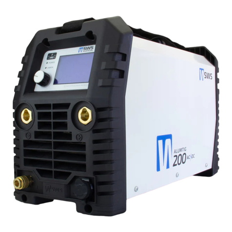
FRONT PANEL DIGITAL DISPLAY
TIG DCEN
VRD
Voltage Reduction Device reduces
maximum unloaded voltage of output
terminals to safe levels (Stick only).
2T/4T Trigger Modes
To operate with the torch switch, select 2T or 4T (2T Double ended arrow 4T separate arrows). For 2T operation,
simply press and hold the switch. The panel program will cycle automatically. When the switch is released, the arc
will downslope and terminate with post gas flow. When in 4T mode, the switch is pressed, and held to start the
pre-flow and the start amps part of the cycle. When released, upslope begins and continues until the amps are
raised to the preset welding amps. When pressed and held again, downslope starts and ramps down to the end amp
stage. When released, the arc terminates, and post flow begins. Remote torch switch (0) is the selected machine
setting (10) 0 Amps.
Power LED
When illuminated the power source is turned on.
Error LED
When illuminated refer to error code on display
and resolve.
Control Dial
1. Rotate to choose setting.
2. Press to select setting.
3. Rotate to adjust setting.
4. Press to store setting.
NOTE: Settings will be stored in the USER
profile chosen at first menu (TIG only).
Argon Outlet
Connect torch gas line and tighten.
NOTE: In most Stick welding
applications DCEP (Direct
Current Electrode Positive) is
used. In some cases when
welding very thin material
using DCEN can be an
advantage.
NOTE: In almost all TIG
welding applications DCEN
(Direct Current Electrode
Negative) is used.
100% Argon 6-15 L/min
depending on conditions.
Torch/Foot Pedal Control
Position locating cut out facing to the top align
and push in to connect. When using the foot
pedal just leave torch switch to the side.
Stick DCEP or DCEN
HF or Li TIG
Weld using Li TIG (for DC only) which requires contact with the metal to initiate the arc or High Frequency Start which
allows non contact starting of the arc (for AC and DC). (HF symbol as pictured).
Welding Amps
This displays the Amps in real time while welding and will hold for 5 seconds aer weld is complete.
Pulse Base Amps
Governs the lower(base or background current) amp value during the pulse cycle.
Pulse Time On (Balance) %
Defines the duty cycle (balance) of the pulse, by dividing the amount of time the pulse stays in the lower or upper
stage of the pulse.
AC Frequency
Governs the number of times per second that the current alternates in AC mode. To achieve greater arc focus
(constriction) and increase puddle agitation while welding in AC mode, increase AC frequency.
Pulse Frequency Hertz (Pulses per second)
Governs the number of times per second that the current alternates in AC mode. To achieve greater arc focus
(constriction) and increase puddle agitation while welding in AC mode, increase AC frequency.
AC Balance
Defines the percent of Electrode Positive (EP) used during AC welding to provide the cleaning action. This divides the
time that the AC cycle spends in (EP) or (EN) during one full AC cycle. Too much cleaning action will result in tungsten
balling or splitting. Too little cleaning can result in dirty, sooty welds and even a dull weld appearance. Higher DCEP
percentage means a greater cleaning action 65% is a good starting point.
AC or DC
The unit features AC/DC operation and uses advanced square wave for AC that has excellent wet in, and arc
controllability.
Welding Sequencer
When the Pro USER mode is selected from the main menu you have complete control over the welding parameters.
Main Menu
AC: 65% 120Hz
PRE-FLOW
START-AMPS
UPSLOPE
PULSE BASE AMPS
PULSE TIME ON %
PULSE FREQUENCY Hz
PULSE OFF AMPS (WELDING AMPS AUTO AC/AUTO DC MODES)
BASE AMPS
DOWNSLOPE
END-AMPS
POST-FLOW
- - - -
See back for recommended Amperage Values and Welding Techniques.
200A


