Weldman POWER DC TIG 200 User manual

WELDMAN POWER PULSE DC TIG 200 HF / LIFT 1
Inverter welder TIG 200 DC
POWER PULSE HF / LIFT
USER MANUAL
ATTENTION:
BEFORE USING THE DETAIL READ THE INSTRUCTIONS. The exact adherence to these instructions will allow for safe use and will allow you and others
to avoid health damage.
AND. SAFETY RULES:
In order to avoid mortal danger observe the following rules:
1. strictly follow these instructions to avoid injury or even death.
2. Construction of the input voltage, a suitable location for the device, the pressure of gas used, etc. All the above must be adapted to the relevant provisions.
3. Bystanders should not stay in the place of welding.
4. Persons with pacemakers are not allowed in the vicinity of the weld without the prior consent of the doctor.
5. Installation and repair should be performed only by persons authorized to do so.
6. Working in the rain is not permitted.
7. For safety must be correctly understood the content of the specification.
TO REDUCE THE RISK OF ELECTRIC SHOCK TO FOLLOW THESE RULES:
1. Avoid contact with the welding circuit. 1. Avoid contact with the welding circuit.
2. Carry out electrical installations in accordance with applicable standards and regulations and safety at work. 2. Carry out electrical installations in accordance with applicable standards and regulations and safety at work.
3. Connecting the welding, inspection or repair should be performed after disconnecting the power supply unit. 3. Connecting the welding, inspection or repair should be performed after disconnecting the power supply unit.
4. Do not use cables with damaged insulation work and / or loosened connections. 4. Do not use cables with damaged insulation work and / or loosened connections.
5. Make sure that the power cord is not damaged. 5. Make sure that the power cord is not damaged.
6. Do not use the device when the housing is removed. 6. Do not use the device when the housing is removed.
7. Wear protective gloves 7. Wear protective gloves
8. Do not touch the handle both mass and torch. 8. Do not touch the handle both mass and torch.
9. Never immerse the electrode in water for cooling 9. Never immerse the electrode in water for cooling
10. It is prohibited to welding operators, arranged above the ground, except for possible use cases 10. It is prohibited to welding operators, arranged above the ground, except for possible use cases
Security platforms.
11. Observe deadlines inspection device. 11. Observe deadlines inspection device.
12. Do not use damaged equipment. 12. Do not use damaged equipment.
13. Disconnect the device from the mains when not in use. 13. Disconnect the device from the mains when not in use.
14. The device should be connected only to the installation provided with a grounding wire (PE). 14. The device should be connected only to the installation provided with a grounding wire (PE).
ATTENTION:
In order to avoid starting a fire, explosion, observe the following rules:
• Do not weld near flammable materials.
• Sparks and hot material can cause fire.
• Weld containers or tubes which contain or contain liquid or gaseous combustible substances
• Do not work on materials cleaned a chlorinated solvent, and does not store the device in the vicinity
•Near the place of work to keep a fire extinguisher
ATTENTION:
In order to avoid tipping cylinder gas explosion or gas regulator should observe the following rules:
(Rolling over of the gas cylinder can cause a fatal accident)

WELDMAN POWER PULSE DC TIG 200 HF / LIFT 2
1. You should properly use gas cylinders.
2. Using our recommended by us or gas reducers.
3. Please refer to the instructions for use reducers and properly apply it.
4. Attach the cylinder by means of a suitable belt or chain located in the delivery device.
5. Keep the bottle away from heat sources and protect from direct sunlight.
6. When opening the valve closer to the gas outlet face. Cut off the gas supply when the welder is not used.
7. Do not lean on the welding torch cylinder and do not touch the electrode to the cylinder
ATTENTION:
Welding works are a source of potential danger to life and health:
• Arc can cause damage to the eyes and skin.
• Chips and welding fumes can cause eye damage or burns.
• Noise can cause hearing loss.
In order to avoid injury to yourself and others nearby, it is necessary that the appropriate means of protection:
1. Wear safety glasses (the welding helmet) with appropriate lenses tinted with UV 1. Wear safety glasses (the welding helmet) with appropriate lenses tinted with UV
2. Wear appropriate protective clothing, 2. Wear appropriate protective clothing,
3. Protection should be extended to other persons in the vicinity of the weld using screens or curtains 3. Protection should be extended to other persons in the vicinity of the weld using screens or curtains
non-reflective.
ATTENTION:
Welding fumes threaten the health:
1. Protection measures should be used to avoid the risk of soot or gases 1. Protection measures should be used to avoid the risk of soot or gases
2. Avoid breathing dust 2. Avoid breathing dust
3. Make sure that the welding work is adequate ventilation and that there are appropriate measures to 3. Make sure that the welding work is adequate ventilation and that there are appropriate measures to
removal of welding fumes.
4. It should be kept in mind when working on materials, primary gases that arise as a result of the evaporation are 4. It should be kept in mind when working on materials, primary gases that arise as a result of the evaporation are
harmful to health.
5. Welder should work in the presence of another person in case of poisoning. 5. Welder should work in the presence of another person in case of poisoning.
II. GENERAL FEATURES II. GENERAL FEATURES
This device POWER TIG series (from now on referred to as welder) was made on the basis of inverter technology, using IGBT and PWM components and MCU.
Welder is designed for welding methods:
1) MMA
2) The DC TIG
3) The DC TIG PULSE
carbon steel, alloy steel, stainless steel, cast iron and copper.
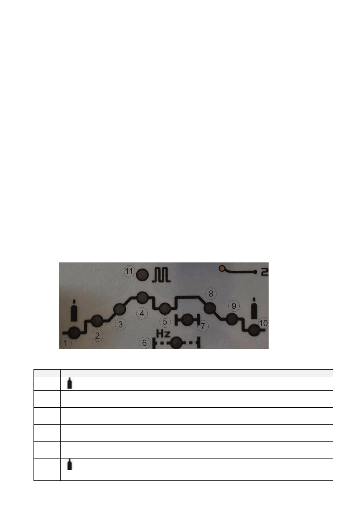
Welding machine can work in a mode 2T / 4T with a contactless (HF) or pin (LIFT), the arc is struck. It has an adjustable ARC FORCE (hold
pressure) and HOT START (hot start).
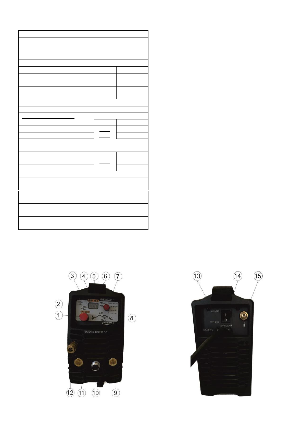
Welder has intelligent thermal protection, overload, undervoltage, overvoltage. Setting the parameters of any device is on the control panel, which is placed on the
multi-function knob and LCD display. This solution enables easy and fast positioning and reading of all the welding parameters. Welder is designed for both home
users and professionals.
Welding equipment has:
• TIG torch 17 WP (DX50) 4 m
• 3m of the ground wire terminal 200A (DX50)
• 3 m cord plug 230
• a gas conduit for connection PU 3.5 m quick coupling type 21 and two clamps
• carrying case made of plastic
gas regulator absent standard equipment. gas regulator absent standard equipment. gas regulator absent standard equipment.

WELDMAN POWER PULSE DC TIG 200 HF / LIFT 3
III. SPECIFICATIONS WELDERS: III. SPECIFICATIONS WELDERS:
MODEL POWER DC TIG 200
GENERAL
POWER SUPPLY VOLTAGE 230V / 50Hz
POWER PROTECTION 20 A
TIG MMA
CURRENT CURRENT MAX POWER 28.6 A 36.6 A
CURRENT INTENSITY POWER EFF. 14.3 A 20 And
VOLTAGE POWER IDLE 62 V
TIG WELDING PARAMETERS 5-200 / 10,2-18V
EFFICIENCY (at 40 ° C) 60% 100%
Welding current 120 A 100 A
Welding voltage 14.8 V 14 V
MMA WELDING PARAMETERS 5-170A / 20,2-26,8V
EFFICIENCY (at 40 ° C) 60% 100%
Welding current 200 A 156 A
Welding voltage 28 V 26.2 V
arc ignition HF
ELECTRODE DIAMETER 1.0-4.0
COOLING FAN
INSULATION CLASS IP23
DEGREE OF PROTECTION F
DIMENSIONS 43x14x25cm
WEIGHT 7.5 kg
Duty cycle is based on the percentage distribution of 10 minutes for the
time in which the machine can weld at rated current welding without
interruption. Duty cycle of 60% means that after 6 minutes of operation is
required for 4 minute interval in order to cool down. Time cooling device
can sometimes
reach up to 15 minutes. Duty cycle 100%
It means that the device can be operated continuously without interruption.
The device has a built-in thermal sensor. In case of overheating, the unit
automatically turns off. In the case of actuation of the overload mechanism,
wait 15 min. to cool the device. After this time should be reduced welding
current, and you can proceed to further work.
IV. BUILDING: IV. BUILDING:

WELDMAN POWER PULSE DC TIG 200 HF / LIFT 4
Lp. Description
front view
1 Multifunction knob (selection and adjustment of parameters) 2
control parameters MMA HOT START (1-10) and ARC FORCE (1-10) 3
display 4
Power LED 5
overload indicator light (alarm) 6
carrying handle (shoulder strap) 7
mode switch; MMA MMA welding GAS: free
flow of gas (test gas)
4T LIFT: TIG mode selection handle 4-stroke at the pole arc is struck (LIFT) 2T LIFT: TIG mode selection handle
2-stroke at the pole arc is struck (LIFT) 4T HF TIG mode selection handle 4T at a non-contact arc is struck (HF) 2T HF
TIG mode selection handle 2T with a non-contact arc is struck (HF) 8
control parameters and TIG TIG PULS 9
slot of positive polarity (MMA handle, a ground terminal TIG) 10
control socket TIG 5-pin of the protective cap 11
cavity of negative polarity (ground terminal MMA TIG) 12
Gas socket (quick type 21)
rear view
13, the input power cord 230V / 50Hz main switch 14 ON / OFF
15
Protective gas connection (plug for quick coupling type 21)
V. INSTALLATION V. INSTALLATION
WORKING ENVIRONMENT
Welder set equal to (maximum angle of inclination of 15 °) and dry surface with a capacity suitable for the weight in order to avoid its overturning.
The device should be placed in a well ventilated area with free air circulation, away from flammable objects (min. Distance from other objects 0.5m). Make sure
not enter the welder dust, corrosive vapors and moisture.
The unit should be set in such a place, not to get into it from welding spatter.
CONNECTING TO NETWORK
Before the electrical connection:
• check whether the data on the plate correspond to the values of the welding voltage and frequency of the network devices in the workplace
• check that the mains supply for the required input power
• check whether the fuse values are consistent with those given in the technical data
• Check the wiring grounding welding. Welding wire is supplied with a 230V plug.
ELECTRICAL CONNECTION SHOULD BE CARRIED OUT BY QUALIFIED PERSONNEL OR EXPERIENCED
PREPARATION TO WORK:
1) Before connecting the welder to the mains, make sure that the main switch (rear panel) is in the off position 1) Before connecting the welder to the mains, make sure that the main switch (rear panel) is in the off position
2) Hollow clamp the wire mass to secure the work piece 2) Hollow clamp the wire mass to secure the work piece
3) The other end of the cable plugs into the mass of positive polarity (+) - TIG, or slot 3) The other end of the cable plugs into the mass of positive polarity (+) - TIG, or slot
of negative polarity (-) - method MMA
4) Plug the operating handle connected to the outlet of the negative polarity (-) - TIG, or slot 4) Plug the operating handle connected to the outlet of the negative polarity (-) - TIG, or slot
of positive polarity (+) - method MMA
5) To the output gas (front panel) connect the plug of the gas holder 5) To the output gas (front panel) connect the plug of the gas holder
(TIG only)
6) The slot-pin controller 5 (front panel) to connect the plug of the control handle 6) The slot-pin controller 5 (front panel) to connect the plug of the control handle
TIG welding (TIG only)

WELDMAN POWER PULSE DC TIG 200 HF / LIFT 5
7) To the input of the shielding gas (plug coupling of the back panel) to connect the 7) To the input of the shielding gas (plug coupling of the back panel) to connect the
feeding gas from the cylinder via the clamp and the coupling (only TIG)
8) The other end of the mass must be fitted to the output reducer gas to the gas cylinder (only 8) The other end of the mass must be fitted to the output reducer gas to the gas cylinder (only
TIG)
9) Prepare the protective clothing (apron, boots and hood / welding helmet) 9) Prepare the protective clothing (apron, boots and hood / welding helmet)
ATTENTION!
Correct connection to the sockets method of MMA is dependent on the properties of the electrodes and the information on the pack by the manufacturer.
VI. WELDING VI. WELDING
When you turn the welder off the main switch on the rear panel of the display symbol P04, meaning the performance test of the PCB, and then illuminates
the LED (4) indicating the welding current, and displays its current value. The value of the welding current can be adjusted by turning the knob SELECT.
After changing the value 3 seconds after the changed value is stored into the cache welder. Before starting the welding parameters must be set other work
on the front panel.
TIG welding and TIG PULS
Depending on the material being welded and individual operator preferences, set the operating parameters. The mode switch to select the mode flare holder
(2-stroke or 4-stroke) and arc ignition way (contact - contactless HF - LIFT).
To access the settings menu of operating parameters, press the multifunction knob - further LED lights welding current (4), then rotate the knob by going to the
parameter to be changed (LED lights continuously). Presses the knob (flashing), rotating knob changing the value of a parameter. After setting the parameter:
- after 3 seconds value is stored into memory, and returns to positions: welding current (4)
- presses the knob (saving value) and turning the knob to move the next parameter. Flashing LED indicates the ability to change the parameter, continuous
light - save the changes. The parameters that are possible to control depend on the selected switch (7) operating mode:
Lp. Description
1
GAS PRE - Time flow of gas prior to arc ignition (control 0.1-1 seconds)
2 current start - only a 4-stroke (5-200 A)
3 welding current rise time (0-10 sec.)
4 welding current (5-200 A)
5 current pulse basis - only in TIG PULS ( 5-200 A) current pulse basis - only in TIG PULS ( 5-200 A) current pulse basis - only in TIG PULS ( 5-200 A)
6 pulse rate - only in PULSE ( 0.5-100 Hz) pulse rate - only in PULSE ( 0.5-100 Hz) pulse rate - only in PULSE ( 0.5-100 Hz)
7 pulse width - only in PULSE ( 5-100%) pulse width - only in PULSE ( 5-100%) pulse width - only in PULSE ( 5-100%)
8 downslope time (0-10 sec.)
9 current end - only a 4-stroke (5-200 A)
10
POST function GAS - Time flow of gas after the expiration of the arc (0.1-10 s).
11 enable / disable function TIG PULS

WELDMAN POWER PULSE DC TIG 200 HF / LIFT 6
After setting the operating parameters it is recommended that the test gas by setting the switch (7) in the position of GAS.
An important element is the clean surface welded:An important element is the clean surface welded:
TIG welding is very sensitive to surface contamination of the metal. Because of that, before the welding process must be removed from the surface of the
welded lubricants, paints, coatings and oxidized.
When these steps We start welding. When these steps We start welding.
The arc welding device in takes place in a contactless manner (HF) - ignition by means of the ionizer, and closer to the electrode base material at a distance
2-3mm and pressing in the handle or in the manner TIG contact (LIFT) by rubbing the electrodes of the welding.
PARWELD handle PROFESSIONAL HR 17 allows you to increase / decrease the current operating buttons located on the handle, without interrupting the
operator.
After work by the operator follows ending welding as a result of the release button on the handle (welding current is gradually reduced and the arc goes out). Until After work by the operator follows ending welding as a result of the release button on the handle (welding current is gradually reduced and the arc goes out). Until After work by the operator follows ending welding as a result of the release button on the handle (welding current is gradually reduced and the arc goes out). Until
the total disappearance of the bow handle can not be removed from the welded surface. Cooling of the weld surface of the cooling gas to prevent oxidation.
After you reboot the welding power supply unit has the operating parameters set last before switching off.
MMA
After selecting switch methods of work (7) MMA, the operator can set three operating parameters: welding current (turning multipurpose knob) and the value HOT
START ARC FORCE.
To do so, press the multifunction knob (1) illuminate the LED ARC FORCE, then hot start. Selection and adjustment of the operating parameters is
carried out similarly while adjusting the parameters in TIG. To obtain high-quality welds remember to remove impurities with the work piece. In order carried out similarly while adjusting the parameters in TIG. To obtain high-quality welds remember to remove impurities with the work piece. In order carried out similarly while adjusting the parameters in TIG. To obtain high-quality welds remember to remove impurities with the work piece. In order
to avoid irregularities during operation, should pay attention to the electrodes used were dry.
When these steps we start welding When these steps we start welding
Ignition in the following by a welded by rubbing the electrode surface, and then lifting up the electrode. To avoid weld spatter should be used electrodes
manufacturer's recommendations.
After completion of the welding welder must be left turned on for a short period in order to cool the unit by the fan. After completion of MMA welding
should be removed from weld slag.
VII. TIPS FOR YOU VII. TIPS FOR YOU
1) The basic types of connections TIG / MMA 1) The basic types of connections TIG / MMA
and butt b corner c overlapping d tee
2) Tungsten electrodes recommended by the manufacturer 2) Tungsten electrodes recommended by the manufacturer
code the size of the
electrodes
RED GREEN GREY GOLD
108 802 108 812 108 822 108 832 1,6x175 mm
108 803 108 813 108 823 108 833 2,0x175 mm
108 804 108 814 108 824 108 834 2,4x175 mm
108 805 108 815 108 825 108 835 3,2x175 mm
108 806 108 816 108 826 108 836 4,0x175 mm
and 对接 接头and 对接 接头 b 角 接 接头b 角 接 接头 c 搭接 接头c 搭接 接头 d T 形 接头d T 形 接头

WELDMAN POWER PULSE DC TIG 200 HF / LIFT 7
POWER 200 TIG welder can weld DC tungsten electrodes: red, gold and grayPOWER 200 TIG welder can weld DC tungsten electrodes: red, gold and gray
3) Tips for welders 3) Tips for welders
Behind ence discoloration around the weld to somehow c and for permanent protection l and Stainlless football Behind ence discoloration around the weld to somehow c and for permanent protection l and Stainlless football Behind ence discoloration around the weld to somehow c and for permanent protection l and Stainlless football Behind ence discoloration around the weld to somehow c and for permanent protection l and Stainlless football Behind ence discoloration around the weld to somehow c and for permanent protection l and Stainlless football Behind ence discoloration around the weld to somehow c and for permanent protection l and Stainlless football Behind ence discoloration around the weld to somehow c and for permanent protection l and Stainlless football
color discoloration Silver and gold Blue Red-gray Grey Black
quality of collateral Best good Correct Wrong Very bad
The relationship discoloration around the weld as about COMPONENTS security alloys ALUThe relationship discoloration around the weld as about COMPONENTS security alloys ALUThe relationship discoloration around the weld as about COMPONENTS security alloys ALU
color discoloration Jasnosrebrzyste Yellow-orange blue-purple Brown White powder oxide
titanium
quality of collateral Best quality of collateral Best good Correct Wrong Very bad
4) Matching accessories and welding parameters 4) Matching accessories and welding parameters
The relationship between the diameter of the gas nozzle and tungsten
The diameter of the gas nozzle / mm Electrode diameter / mm
6.4 0.5
8 1.0
9.5 1.6 or 2.4
11.1 3.2
selected plant res ratio of the diameter of the gas nozzle to cupcake and the flow of shielding gas selected plant res ratio of the diameter of the gas nozzle to cupcake and the flow of shielding gas selected plant res ratio of the diameter of the gas nozzle to cupcake and the flow of shielding gas
Welding current range / A
Normal polarity of the DC + AC
The diameter of the gas
nozzle / mm
gas flow
/ L · min- 1/ L · min- 1
The diameter of the gas
nozzle / mm
gas flow
/ L · min- 1/ L · min- 1
10 ~ 100 10 ~ 100 10 ~ 100 4 ~ 9.5 4 ~ 9.5 4 ~ 9.5 4 ~ 5 4 ~ 5 4 ~ 5 8 ~ 9.5 8 ~ 9.5 8 ~ 9.5 6 ~ 8 6 ~ 8 6 ~ 8
101 ~ 150 101 ~ 150 101 ~ 150 4 ~ 9.5 4 ~ 9.5 4 ~ 9.5 4 ~ 7 4 ~ 7 4 ~ 7 9.5 ~ 11 9.5 ~ 11 9.5 ~ 11 7 ~ 10 7 ~ 10 7 ~ 10
151 ~ 200 151 ~ 200 151 ~ 200 6 ~ 13 6 ~ 13 6 ~ 13 6 ~ 8 6 ~ 8 6 ~ 8 11 ~ 13 11 ~ 13 11 ~ 13 7 ~ 10 7 ~ 10 7 ~ 10
201 ~ 300 201 ~ 300 201 ~ 300 8 ~ 13 8 ~ 13 8 ~ 13 8 ~ 9 8 ~ 9 8 ~ 9 13 ~ 16 13 ~ 16 13 ~ 16 8 ~ 15 8 ~ 15 8 ~ 15
The shape of the electrodes y tungsten and scope welding current The shape of the electrodes y tungsten and scope welding current The shape of the electrodes y tungsten and scope welding current
The diameter of the
tungsten electrode / mm
top diameter
cone / mm The cone angle ( about)The cone angle ( about) Welding current / A Current Mode PULS
1.0 0.125 12 2 ~ 15 2 ~ 15 2 ~ 15 2 ~ 25 2 ~ 25 2 ~ 25
1.0 0.25 20 5 ~ thirty 5 ~ thirty 5 ~ thirty 5 ~ 60 5 ~ 60 5 ~ 60
1.6 0.5 25 8 ~ 50 8 ~ 50 8 ~ 50 8 ~ 100 8 ~ 100 8 ~ 100
1.6 0.8 thirty 10 ~ 70 10 ~ 70 10 ~ 70 10 ~ 140 10 ~ 140 10 ~ 140
2.4 0.8 35 12 ~ 90 12 ~ 90 12 ~ 90 12 ~ 180 12 ~ 180 12 ~ 180
2.4 1.1 45 15 ~ 150 15 ~ 150 15 ~ 150 15 ~ 250 15 ~ 250 15 ~ 250
3.2 1.1 60 20 ~ 200 20 ~ 200 20 ~ 200 20 ~ 300 20 ~ 300 20 ~ 300
VIII. MAINTENANCE:
Before maintenance, disconnect the welding device from the mains and allow to cool handle. Maintenance work daily:
▪check the welding cables and connections
▪check the status of consumables (gas nozzle, the nozzle current)
▪replace worn or damaged parts of the monthly
maintenance operations:
▪clean the inside of compressed air welder
▪check the electrical connections inside the welder

WELDMAN POWER PULSE DC TIG 200 HF / LIFT 8
IX. WARRANTY: IX. WARRANTY:
The manufacturer guarantees the correct functioning of the equipment and is committed to the free exchange of parts that spoil as a result of poor quality
material or manufacturing defects within 12 months from the launch date equipment, certified warranty. The cost of sending the unit to the manufacturer and the
manufacturer to the user during the warranty period covers the user device.
Devices that have been sold in EU member states as consumer goods, are covered by the 24 month warranty period, the cost of sending the unit to the
manufacturer and the manufacturer to the user during the warranty period covers the device manufacturer in accordance with the European Directive 1999/44 / EC.
The warranty card is only valid if accompanied by a receipt or purchase invoice. Difficulties arising from misuse, negligence or breach of the device are not
covered by the warranty. The manufacturer is not liable for any direct or indirect damages.
Warranty Card.
Model: POWER PULSE DC TIG 200 HF / LIFT
no:
Date
sales:
Dealer:
DELKARACJA CONFORMITY
Importer DELTA-TECH Sp. z oo with its seat in Lublin Street Stanislaw Lem 26 on the basis of the declaration of the
manufacturer, declare with full responsibility that the device complies with the following directives: EN 60974-10: 2014 + A1: 2015 and manufacturer, declare with full responsibility that the device complies with the following directives: EN 60974-10: 2014 + A1: 2015 and
EN 60974-1: 2012 LVD 2014/35 / EU, EC 2014/30 / EU.
The symbol, which means sorting of waste electrical and electronic equipment. It is forbidden to
suppress the equipment as mixed municipal solid waste, the responsibility of the user is directed
to an authorized waste collecting centers.
Table of contents
Other Weldman Welding System manuals
Popular Welding System manuals by other brands

Lincoln Electric
Lincoln Electric PF44 Operator's manual

Cebora
Cebora POWER SPOT 5700 instruction manual

Victor
Victor CUTMASTER A40 operating manual

EWM
EWM MT221-301G F2 operating instructions

Lincoln Electric
Lincoln Electric HANDY MIG IM756-A Operator's manual

Zenit Powertools
Zenit Powertools MMA-200/2 instruction manual

Costway
Costway ET10011US user manual

WELDKAR
WELDKAR WK TIG 2025 AC/DC Pulse instruction manual

Cebora
Cebora WIN TIG DC 220M instruction manual

MasterCraft
MasterCraft WG2063 Operating instructions & parts manual

CEMONT
CEMONT SPEEDY 130 Safety instruction for use and maintenance

Leister
Leister GEOSTAR G5 LQS operating instructions