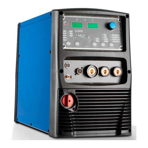
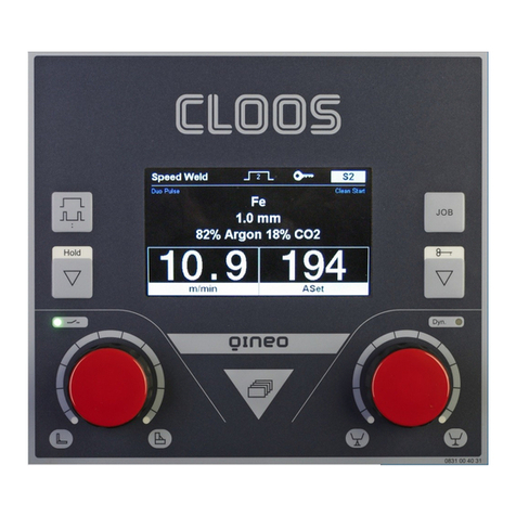
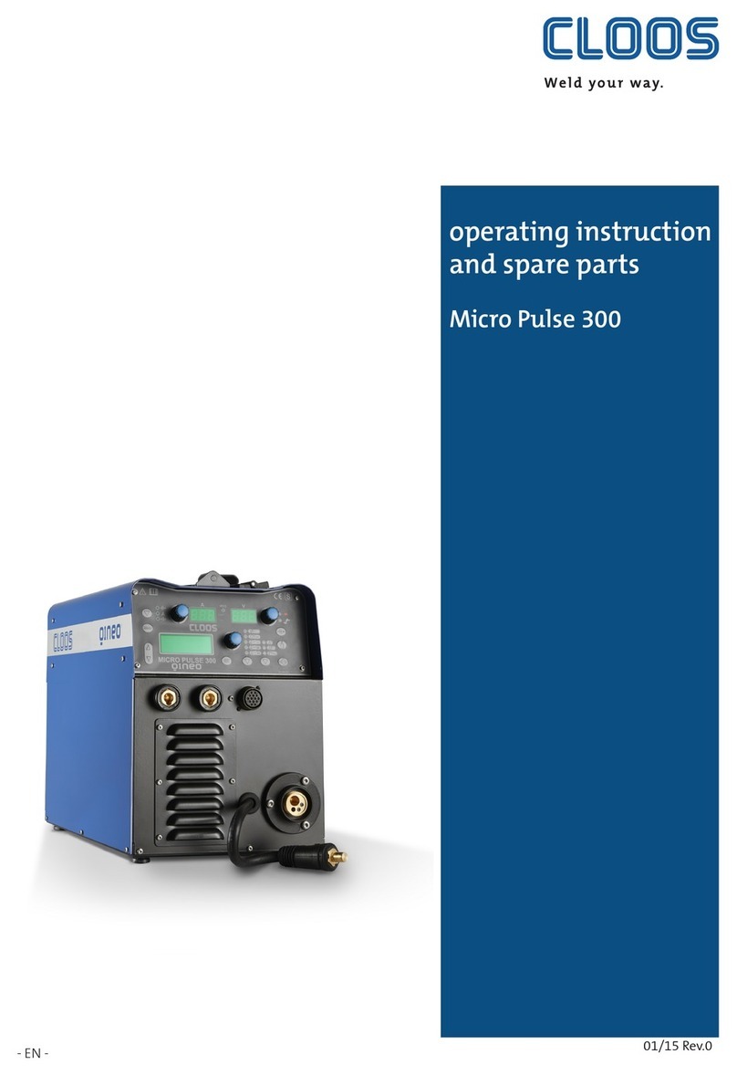
Cloos QINEO User manual

-En-
This is a translation of the original
operating instructions.
WP-L - 02/19 - Rev.1.1
Keep for future use
OPERATING
INSTRUCTIONS
QINEO CHAMP
PrO

Carl Cloos Schweisstechnik GmbH
Carl-Cloos-Strasse 1
35708 Haiger
GERMANY
Telephone +49 (0)2773 85-0
Telefax +49 (0)2773 85-275
E-mail [email protected]
www.cloos.de

CARL CLOOS Schweisstechnik GmbH
Industriestrasse
35708 Haiger/Germany
Tel. +49 (0)2773/85-0
Fax. +49 (0)2773/85-275
mail: info@cloos.de
www.cloos.de
EU declaration of conformity
No. CMM0516QNCH_01
Product description: MIG/MAG welding machine
Model name: QINEO CHAMP, QINEO CHAMP PRO, WD
Serial number: Refer to the nameplate on the back of the device
Manufacturer: CARL CLOOS Schweisstechnik GmbH
Address:
The manufacturer bears sole responsibility for issuing the declaration of conformity.
Low Voltage Directive:
EMC Directive:
RoHS Directive:
- EN 60974-1 Arc Welding Equipment
Part 1: Welding Power Sources
- EN 60974-2 Arc Welding Equipment
Part 2: Liquid Cooling Systems
- EN 60974-5 Arc Welding Equipment
Part 5: Wire Feed Units
- EN 60974-10 Arc Welding Equipment
Part 10: Requirements of Electromagnetic Compatibility (EMC)
Signed for and in the name of:
CARL CLOOS Schweisstechnik GmbH
35708 Haiger, 30/05/16
Signature: Gerald Mies
Identification of signatory: Managing director
Agreement of the product stated with the regulations in the directives applied is verified with conformance to the
following standards and regulations:
Major conversions and add-ons which are not carried out by the manufacturer or the manufacturer’s authorised
representative(s) result in termination of this declaration of conformity.
Industriestrasse 22-36
35708 Haiger
Germany
2014/35/EU
Directive of the European Parliament and of the Council of 26 February 2014 on the
harmonisation of laws of Member States relating to the making available on the market of electrical
equipment designed for use within certain voltage limits; Official Journal of the EU L96, 29/03/2014,
Pages 357 - 374
2014/30/EU Directive of the European Parliament and of the Council of 26 February 2014 on the
harmonisation of laws of Member States relating to electromagnetic compatibility; Official Journal of the
EU L96, 29/03/2014, Pages 79 - 106
2011/65 /EU
Directive of the European Parliament and of the Council of 8 June 2011 on the restriction
of use of certain hazardous substances in electrical and electronic equipment; Official Journal of the EU
L174, 01/07/2011, Pages 88 - 110
The aforementioned products covered by the declaration satisfy the relevant
statutory provisions of the Union:


Contents
Block 1 Operational Safety 11
1. Foreword ..........................................................................................................12
2. Safety symbols in this document ................................................................13
3. Safety specifications for MIG/MAG welding machines...........................14
3.1 Basic safety specifications for the operation of the welding machine.....................14
3.2 Application as directed...................................................................................................................15
3.3 Self protection and personal protection when MIG/MAG welding...........................15
3.4 Electrical danger due to mains current and welding current......................................18
3.5 Particular dangers when MIG/MAG welding.......................................................................24
3.6 Safety precautions in daily operation......................................................................................25
4. Environmental circumstances .....................................................................27
4.1 Storage...................................................................................................................................................27
4.2 Transport ..............................................................................................................................................27
5. Qualification of users ....................................................................................28
Block 2 Basic information Qineo Champ Pro 29
1. Connection overview welding power source............................................30
2. Connection overview optional interfaces..................................................32
3. Connection overview QWD- M4...................................................................33
4. Connection overview QWD-A4.....................................................................33
5. Product description........................................................................................34
6. Commissioning...............................................................................................36
7. Shutdown / Recycling....................................................................................40
8. Technical data .................................................................................................41
Block 3 PREMIUM operating module 43
1. Operating controls .........................................................................................45
2. Main menu ......................................................................................................46
3. MAIN - Synergy................................................................................................47
4. MAIN - Op. (operating modes) .....................................................................47
4.1 2-cycle.....................................................................................................................................................47
4.2 4-cycle.....................................................................................................................................................48
4.3 Super 4-cycle .......................................................................................................................................49
4.4 Spot welding .......................................................................................................................................49
4.5 External..................................................................................................................................................49
5. MAIN process...................................................................................................50
5.1 Electrode................................................................................................................................................50
5.2 TIG............................................................................................................................................................50
5.3 Speed Pulse..........................................................................................................................................50
5.4 Pulse........................................................................................................................................................50
5.5 MIG/MAG Normal.............................................................................................................................50
5.6 Syn off.....................................................................................................................................................51
5.7 Processes with the appendix CW (Cold Weld)......................................................................51
5.7.1 S-Pulse CW............................................................................................................................................51
5.7.2 Normal CW...........................................................................................................................................52
5.8 Rapid Weld ...........................................................................................................................................52

6. MAIN - Function..............................................................................................53
6.1 DuoPulse...............................................................................................................................................53
6.2 CleanStart.............................................................................................................................................53
6.3 Blow through ......................................................................................................................................53
6.4 Wire forward.......................................................................................................................................54
6.5 Wire backward ...................................................................................................................................54
6.6 Gas manually......................................................................................................................................54
6.7 Start manually....................................................................................................................................54
7. MAIN - Progr. (Programming).......................................................................55
7.1 Parameters in the operating modes 2-cycle and 4-cycle.................................................57
7.2 Parameters in the operating mode Super-4-cycle..............................................................57
7.3 Parameters in operating mode Spot Welding / Interval .................................................59
7.4 Setting ranges ....................................................................................................................................60
7.4.1 Input of setting ranges...................................................................................................................60
7.4.2 Prerequisite to use the setting ranges ....................................................................................61
7.4.3 Deactivating the setting ranges.................................................................................................63
7.5 MAIN - Programming - Tandem..................................................................................................63
7.6 MAIN - Programming - Pulse synchronisation ....................................................................63
7.7 "Expert Mode" (single parameter mode)................................................................................64
7.7.1 Main parameters in the "Expert Mode"..................................................................................64
7.7.2 Secondary parameters in the "Expert Mode" .......................................................................65
7.7.3 "DuoPulse parameters" in the "Expert Mode"......................................................................66
8. MAIN - Measured values ...............................................................................67
8.1 Operating data...................................................................................................................................67
8.1.1 Data set switching 1/2 ...................................................................................................................68
8.1.2 Seam counter Setup ........................................................................................................................69
8.1.3 Consumption costs ..........................................................................................................................70
9. MAIN - Display.................................................................................................70
10. MAIN (2) - Config (Configuration)................................................................72
10.1 Config - General.................................................................................................................................72
10.1.1 Display brightness............................................................................................................................72
10.1.2 MHW 405 TQ .......................................................................................................................................72
10.1.3 Control coolant pump and fan....................................................................................................73
10.2 Config - General (2)...........................................................................................................................73
10.3 Config - General (3)...........................................................................................................................74
10.3.1 Config - General - Basic settings.................................................................................................74
10.3.2 Config - General - SD module ......................................................................................................78
10.3.3 Config - General - Options.............................................................................................................78
10.4 Config - Water monitoring............................................................................................................80
10.5 Config - Compensation...................................................................................................................81
10.6 Access rights........................................................................................................................................83
10.6.1 Config - Access management......................................................................................................83
10.6.2 Config - User management and PAK (option)......................................................................85
10.7 Config - PC adaptation....................................................................................................................91
10.8 Config - Clock.......................................................................................................................................91
10.9 Config - Process monitoring.........................................................................................................92
11. MAIN (2) - Diagnostics ...................................................................................93
11.1 Diagnostics Cooling ........................................................................................................................94
11.2 Diagnostics Software versions....................................................................................................94
11.3 Diagnostics I / 0 (Inputs and Outputs)....................................................................................95
11.4 Diagnostics VBC module................................................................................................................96
11.5 Diagnostics QWD..............................................................................................................................97
11.6 Diagnostics PC adaptation ...........................................................................................................98

11.7 Diagnostics Tandem.........................................................................................................................98
11.8 Diagnostics pulsed arc synchronisation.................................................................................99
11.9 Diagnostics System logbook ........................................................................................................99
11.9.1 Diagnostics Robot (from x.11.30 on).....................................................................................101
12. MAIN (2) - Language.................................................................................... 102
13. MAIN (2) - Data backup .............................................................................. 103
13.1 Copy job to SD memory card.....................................................................................................103
13.2 Read job from SD memory card...............................................................................................104
13.3 Copy characteristic curve to SD card.....................................................................................104
13.4 Read characteristic curve from SD memory card ............................................................104
13.5 Copy configuration data to SD memory card....................................................................104
13.6 Read configuration data from SD memory card..............................................................104
14. User log on/off.............................................................................................. 105
14.1 MAIN (2) - Log on............................................................................................................................105
14.2 MAIN (2) - Log off ...........................................................................................................................105
15. Job mode ....................................................................................................... 106
15.1 Save job...............................................................................................................................................106
15.2 Overwrite an existing job...........................................................................................................107
15.3 Copy a job ..........................................................................................................................................107
15.4 Activate job .......................................................................................................................................108
Block 4 Additional information 109
1. RC Plus (Remote Control)............................................................................ 110
2. MHW 405 TQ (2-button torch)................................................................... 111
3. SD module..................................................................................................... 112
3.1 Monitoring channels....................................................................................................................112
3.2 Submenus .........................................................................................................................................116
3.3 Configure monitoring channel................................................................................................117
3.4 Logbook...............................................................................................................................................119
3.5 Combine the application example SD monitoring with QIROX controller..........122
Block 5 Qineo Wire Drive 125
1. Technical data .............................................................................................. 126
1.1 Weight.................................................................................................................................................126
1.2 Dimensions.......................................................................................................................................126
1.3 Ambient conditions ......................................................................................................................126
1.4 Compatibility list............................................................................................................................126
2. QINEO Wire Drive M4.................................................................................. 127
2.1 Connection overview M4............................................................................................................128
3. QINEO Wire Drive A4................................................................................... 129
3.1 Structure and function A4.........................................................................................................130
4. QINEO Wire Drive AR4 ................................................................................ 131
4.1 Connection overview AR4...........................................................................................................132
5. Function ........................................................................................................ 133
5.1 Button "Gas manually"................................................................................................................133
5.1.1 Adjustment of the gas flow rate .............................................................................................133
5.2 Button "Wire forward" or "Wire backward"........................................................................134

6. Commissioning............................................................................................ 135
6.1 Safety instructions for commissioning................................................................................135
6.1.1 Risks due to mechanical hazards............................................................................................135
6.1.2 Risks due to electrical hazards .................................................................................................135
6.2 Reducing insert...............................................................................................................................136
6.2.1 Disassembly reducing insert QWD-M ..................................................................................136
6.3 Installation/change of the wire drive rollers.....................................................................137
6.3.1 QWD-M...............................................................................................................................................137
6.4 Inserting the welding wire ........................................................................................................139
6.4.1 QWD-M...............................................................................................................................................139
6.5 Adjustment of the pressure clamps......................................................................................141
7. Maintenance ................................................................................................ 142
8. Error list ......................................................................................................... 143
9. Disposal and Recycling ............................................................................... 144
Block 6a Error messages 145
1. Error messages............................................................................................. 146
1.1 Error list..............................................................................................................................................147
Block 6b General maintenance instructions 159
1. Maintenance and Care ............................................................................... 160
1.1 Regular testing................................................................................................................................161
1.2 Semi-annual testing.....................................................................................................................162
1.3 Annual testing.................................................................................................................................162
1.4 Special testing .................................................................................................................................163
1.4.1 Optional filter mat in the cooling unit.................................................................................163
1.4.2 Crane suspensions at the wire drive unit...........................................................................163
1.4.3 Electrolytic capacitors of the transistor cascades...........................................................163
Block 7 Automation 165
1. Interfaces....................................................................................................... 166
1.1 QOMI Module (Open Machine Interface)............................................................................166
1.2 Profibus Module (Process Field Bus)......................................................................................166
1.3 ProfiNet Module .............................................................................................................................167
1.4 DeviceNet Module .........................................................................................................................167
1.5 Ethernet-IP Module .......................................................................................................................167
2. QIROX Technology Interface (QTI) ............................................................. 168
2.1 Software compatibility................................................................................................................168
2.2 Assignment of protocol type for Tandem operation......................................................168
2.3 Additional welding processes protocol type 2..................................................................168
2.4 Control of communication between welding power source and robot ...............168
3. Basic configuration Operating mode "Tandem" ................................... 169
3.1 Connection diagram.....................................................................................................................169
3.2 Conditions.........................................................................................................................................169
3.3 Pre-adjustments.............................................................................................................................170

3.3.1 QIROX robots ....................................................................................................................................170
3.3.2 QINEO welding power sources ................................................................................................170
3.4 Job programming QINEO welding power sources..........................................................172
3.4.1 Select operating mode "Tandem" ...........................................................................................172
3.4.2 Adjustment of the synergy variant........................................................................................174
3.4.3 "Active QWD" setting....................................................................................................................175
4. Pulse synchronisation................................................................................. 178
4.1 Configuration...................................................................................................................................178
4.1.1 Synchronisation mode.................................................................................................................179
4.1.2 Phase shift.........................................................................................................................................180
5. Job allocation................................................................................................ 182


11
Operational safety
Block 1 Operational Safety

12
Dear customer,
You have decided to purchase a CLOOS shielding gas welding
machine from the QINEO series. This is a brand-name
product which will meet your highest quality requirements.
Messrs. CLOOS Schweisstechnik GmbH are a company
certified to DIN ISO 9001 and who put great emphasis on
development, manufacture and quality of their products.
The power sources and the accessories in the QINEO series
have been developed, designed and manufactured according
to the generally accepted safety regulations. This is
confirmed by the declaration of conformity and CE marking.
The technical design, texts and photographs of the welding
machines correspond to the development status at the date
of the printing of this documentation.
The contents of the documentation will be adapted to
technical developments.
Subject to alterations.
The copyright law for the complete documentation remains
with the manufacturer.
1. Foreword

13
Operational safety
INFO!
Practical tips and other useful information!
ATTENTION!
The signal word indicates a hazard without risk of a physical
impairment, which, if not avoided, can lead to property
damage.
CAUTION!
Describes a probably dangerous situation which may result
in minor injury or damage to property.
WARNING!
Describes a probably dangerous situation which may result
in severe injury or even death.
DANGER!
Describes an imminent danger which may result in severest
injury or even death.
Hazardous materials !
2. Safety symbols in this
document
INFO!
ATTENTION!
CAUTION!
WARNING!
DANGER!
XnXn

14
Connection, service and repair works must only be carried out
by qualified personnel who have the appropriate professional
training and sufficient experience and knowledge of the
power source and who are able to perform the required works
in accordance with the relevant safety specifications.
(Electrician as per BGV A3, Electrical plants and operating
equipment).
The design and construction of the welding machine
corresponds to DIN EN 60 974 - 1. (Arc welding equipment,
part 1, Welding power sources).
It corresponds to the latest state-of-the-art in technology and
the recognised rules of safety engineering. It must be operated
by trained personnel or users who have been familiarized
with the machine to prevent danger due to inappropriate
handling or operation which is not in accordance with the
specifications.
For the use in Germany the following regulations have to be
considered!
• Safety regulations BGV D1
• Safety regulations BGV A3
• National and regional fire protection rules
• Works on supply voltage, repairs and maintenance must
be carried out by qualified personnel only (electricians as
defined in BGV A3).
• Movable mains supply and welding lines must be protect-
ed against damage.
• Do not install the power source in a working area where
welding with increased electrical hazard takes place.
• The machine must be switched off and disconnected for
all maintenance work.
• All labels and danger signs on the welding machine must
be kept easily legible and must not be covered, coated,
pasted over or removed.
• The operating manual must always be available near the
welding machine. In addition, the regional rules for pre-
vention of accidents and environment must be available
and be adhered to.
If repair work is carried out by unauthorised persons and
safety regulations are not adhered to, any guarantee and
warranty claims become invalid.
3. Safety specifications for MIG/MAG welding machines
WARNING!
3.1 Basic safety
specifications for
the operation of the
welding machine
INFO!

15
Operational safety
The welding machine is exclusively intended for application as
directed. The welding machine must only be used for welding
processes and working ranges scheduled on the power sign.
Every other use is regarded as
not directed.
The manufacturer is not liable for damages occurred hereof.
The power source must never be used for the following works:
• Thawing of pipe lines
• Loading of batteries/accumulators
• Starting of motors
The machine is intended for industrial use and must not
be used in residential buildings. The manufacturer is not
liable for damages due to use in residential buildings. The
power source is subject to the standards IEC 61000-3-4 or
EN 61000-3-2.
• When welding, dry and flame resistant protective clothing,
apron, helmet and gloves as well as solid, well-insulated
work shoes should be worn.
3.3.1. Danger due to electromagnetic fields (EMF)
According to the Accident Prevention Regulations BGV B11
"Electro-magnetic fields" the permissible values of electric
and magnetic fields will not be exceeded with arc welding
systems in the environment of the power source, the feed
lines and the torch.
However, the safety values for persons with active implants
(cardiac pacemakers, defibrillators and similar) might be
exceeded in the environment of welding machines.
Due to the low magnetic fields of arc welding systems,
a safety distance of 1 m to the live parts such as cable
assemblies, cables and torch/arc is recommended. During
MIG/MAG welding, the danger is due to magnetic fields and
during TIG welding due to the high voltage pulses of arc
ignition units.
3.2 Application as directed
CAUTION!
3.3 Self protection and
personal protection
when MIG/MAG
welding
INFO!

16
In practice, various models of active implants are used, the
thresholdvaluesofwhichdependondifferentparameters(type
of implant, operating mode, programming of the implant).
As far as the occupational safety is concerned, an individual
risk assessment is recommended in each individual case. If
this is not possible, the generally valid safety values - which
are based on the most sensible implants - can be applied,
according to standard EN DIN VDE 0848-3-1 "Safety in electric,
magnetic and electromagnetic fields - Protection of persons
with active physical aids".
3.3.2. High frequency electromagnetic compatibility
EMC machine classification in accordance with standard EN
60974-10 (see type plate or the specification of technical
data).
Class B machines meet the EMC requirements in industrial
and residential areas, including residential areas connected
to the public low voltage supply network.
Class A machines are not intended for use in residential areas
where electric energy is drawn from the public low voltage
supply network. It is difficult to guarantee electromagnetic
compatibilityfor classA machinesdue to conducted emissions
and radiated interferences in these areas.
3.3.3. Radiation
Ultraviolet and infrared radiation are released during
welding.
• Protect skin and particularly the eyes. Keep eye drops and
skin cream with a high sun protection factor available.
• Always use safety glasses according to DIN EN 166 and
DIN EN 379 in your welder’s protective shield or helmet.
• Protect other persons in the vicinity of the welding area
from UV rays and spatter by suitable, non-flammable par-
tition walls.
• Always wear safety glasses with side protection when you
are in an area where welding takes place or where slag is
removed.

17
Operational safety
3.3.4. Gases and vapours
• All metal vapours are harmful to health!
• Be careful with alloys which contain lead, cadmium, cop-
per, zinc, nickel, chrome and beryllium.
• Chloric cleaning and degreasing agents can lead to the
formation of the toxic gas phosgene due to the decompo-
sition in the arc (risk of suffocation!).
• Risk of poisoning in narrow places!
• If shielding gas hoses are not tight or the shielding gas
valve gets caught unintentionally, shielding gas may es-
cape to such an extent that the oxygen content of the in-
haled air decreases, symptoms of poisoning appear which
may lead to unconsciousness and suffocation. (Argon and
CO2are heavier than air).
• Sufficient fresh air must be provided! Please check the gas
supplying parts in regular intervals.
• Use fume extraction systems. Pay attention to the national
and regional safety regulations.
3.3.5. Fire prevention (explosion)
• Remove all flammable materials around the welding place
or cover these with a non-flammable or at least hardly
combustible material.
• Hot slag or spatter might cause fires if in contact with
flammable materials.
• Only use shielding gas mixtures suitable for welding con-
sisting of e. g. Argon, Helium, CO2and O2.
Never use flammable gases such as acetylene, propane or
pure hydrogen.
Never weld on drums, tanks,pipes or similar containers unless
they have been thoroughly cleaned and prepared according
to the relevant national and international standards.
Make sure that no toxic, flammable or explosive vapours can
develop.
Ensure that suitable fire-fighting equipment such as water,
sand or fire extinguishers are within easy reach.
CAUTION!
WARNING!
WARNING!
WARNING!
WARNING!
DANGER!
CAUTION!

18
Confined spaces must have a free passage allowing escape in
case of danger.
Please observe the weld area and its surroundings when
welding has finished. Fire may break out later due to
smouldering.
3.3.6. Noise
• Noise may cause permanent damage to your hearing. Dur-
ing welding the admissible noise level might be exceeded
under unfavourable conditions.
• Please make sure that the admissible maximum values
are not exceeded (Security Administrator).
• If the maximum values are exceeded, a suitable ear pro-
tection (earplugs or earmuffs) has to be used.
3.4 Electrical danger due to mains current and welding current
3.4.1. General information
An electric shock can prove fatal. Basically, every electric shock
is extremely dangerous.
• Do not touch live parts within or outside the power
source!
• During MIG/MAG welding, the welding wire, the wire coil,
the drive rollers as well as all metal parts which touch the
welding wire, are live.
• All cables must be tight, undamaged, insulated and suf-
ficiently dimensioned. The negative cable (earth cable) and
the positive cable are locked by turning to the right. Loose
plugs affect the arc and thus the welding behaviour of the
power source to a considerable extent.
• Switch the welding machine off when not in use to pre-
vent any electrical risk.
• Avoid contact with metal parts, wear dry, insulating cloth-
ing and safety shoes.
• Power sources may only be used when all covers are avail-
able and correctly installed.
WARNING!

19
Operational safety
3.4.2. Mains connection
The power supply must be installed by qualified personnel
only!
Please ensure that the mains voltage to be used is identical to
the operating voltage indicated on the machine type plate.
According to the connection regulations the machine has
to be fused and connected by means of a mains cable. You
will find the connection rules inside the power source after
removal of the cover or side panel. The cross section of the
connection cable must be adequate.
The machine must be connected to a three-phase four-wire
system with earth conductor and operated.
Connection to ungrounded networks (e.g. IT networks) or
asymmetrically grounded networks is only permitted with an
appropriate isolating transformer
Item Designation Colour
L1 Phase conductor 1 brown
L2 Phase conductor 2 black
L3 Phase conductor 3 grey
N Earth conductor blue
PE Protective conductor green-yellow
The terminal voltage of the power source can be up to 113 V
DC or 48 V AC !
INFO!
CAUTION!
ATTENTION!
L1
L2
L3
N
PE
CAUTION!

20
For welding power sources with multiple connection,
observe the corresponding wiring on the main and control
transformer (400 V / 480 V / etc.).
Although the power source is "marked S" for welding in
environments with increased electrical hazard, the power
source itself must not be installed in such places (mains
voltage 400V).
Only the welding torch and wire drive unit may be installed
and operated in such places.
Depending on the process used, it may happen that there is
an addition of the two open circuit voltages between the
welding electrodes of two power sources. There is possibly
the risk of danger to life if both potentials are touched at the
same time, see Figure 3.
CAUTION!
Figure 1. Mains voltage main transformer Figure 2. Mains voltage control transformer
ATTENTION!
Figure 3. Added open circuit voltages
This manual suits for next models
2
Table of contents
Other Cloos Welding System manuals
Popular Welding System manuals by other brands

Thermal Dynamics
Thermal Dynamics SIGNATURE PAK 1250XRTM owner's manual

Lincoln Electric
Lincoln Electric Air Vantage 600 owner's manual

Jasic
Jasic VIPERMIG 180i manual
DINSEO
DINSEO DIX GO 1206.M C Operation manual

ESAB
ESAB Migmaster 173 instruction manual

GÜDE
GÜDE GPS-E 40 A Translation of the original instructions
