Weldman POWER MIG 210 LCD User manual

WELDMAN SEMI-AUTOMATIC LCD POWER MIG 210 MIG / MAG / MMA / TIG DC LIFT Page 1
SEMI-AUTOMATIC MIG / MAG / MMA / TIG
POWER MIG 210 LCD
USER MANUAL
ATTENTION:
BEFORE USING THE DETAIL READ THE INSTRUCTIONS. The exact adherence to these instructions will allow for safe use and will
allow you and others to avoid health damage.
AND. SAFETY RULES:
In order to avoid mortal danger observe the following rules:
1. strictly follow these instructions to avoid injury or even death.
2. Construction of the input voltage, a suitable location for the device, the pressure of gas used, etc. All the above must be adapted to the
relevant provisions.
3. Bystanders should not stay in the place of welding.
4. Persons with pacemakers are not allowed in the vicinity of the weld without the prior consent of the doctor.
5. Installation and repair should be performed only by persons authorized to do so.
6. Working in the rain is not permitted.
7. For safety must be correctly understood the content of the specification.
TO REDUCE THE RISK OF ELECTRIC SHOCK TO FOLLOW THESE RULES:
1. Avoid contact with the welding circuit. 1. Avoid contact with the welding circuit.
2. Carry out electrical installations in accordance with applicable standards and regulations of health and safety 2. Carry out electrical installations in accordance with applicable standards and regulations of health and safety
work.
3. Connecting the welding, inspection or repair should be performed following the disconnection 3. Connecting the welding, inspection or repair should be performed following the disconnection
power supply unit.
4. Do not use cables with damaged insulation work and / or loosened connections. 4. Do not use cables with damaged insulation work and / or loosened connections.
5. Make sure that the power cord is not damaged. 5. Make sure that the power cord is not damaged.
6. Do not use the device when the housing is removed. 6. Do not use the device when the housing is removed.
7. Wear protective gloves 7. Wear protective gloves
8. Do not touch the handle both mass and torch. 8. Do not touch the handle both mass and torch.
9. Never immerse the electrode in water for cooling 9. Never immerse the electrode in water for cooling
10. It is forbidden to welding operators located above the ground, with the exception of possible cases 10. It is forbidden to welding operators located above the ground, with the exception of possible cases
application security platforms.
11. Observe deadlines inspection device. 11. Observe deadlines inspection device.
12. Do not use damaged equipment. 12. Do not use damaged equipment.
13. Disconnect the device from the mains when not in use. 13. Disconnect the device from the mains when not in use.
14. The device should be connected only to the installation provided with a grounding wire (PE). 14. The device should be connected only to the installation provided with a grounding wire (PE).
ATTENTION:
In order to avoid starting a fire, explosion, observe the following rules:
• Do not weld near flammable materials.
• Sparks and hot material can cause fire.

WELDMAN SEMI-AUTOMATIC LCD POWER MIG 210 MIG / MAG / MMA / TIG DC LIFT Page 2
• Weld containers or tubes which contain or contain liquid or gaseous combustible substances
• Do not work on materials cleaned a chlorinated solvent, and does not store the device in the vicinity
•Near the place of work to keep a fire extinguisher
ATTENTION:
In order to avoid tipping cylinder gas explosion or gas regulator should observe the following rules:
Overturning a gas cylinder may result in fatal accident
1. You should properly use gas cylinders. 1. You should properly use gas cylinders.
2. Using our recommended by us or gas reducers. 2. Using our recommended by us or gas reducers.
3. Please refer to the instructions for use reducers and properly apply it. 3. Please refer to the instructions for use reducers and properly apply it.
4. Attach the cylinder by means of a suitable belt or chain located on the equipment 4. Attach the cylinder by means of a suitable belt or chain located on the equipment
devices.
5. Keep the bottle away from heat sources and protect from direct exposure 5. Keep the bottle away from heat sources and protect from direct exposure
solar.
6. When opening the valve closer to the gas outlet face. Cut off the gas supply when the welder is not6. When opening the valve closer to the gas outlet face. Cut off the gas supply when the welder is not
used.
7. Do not lean on the welding torch cylinder and do not touch the electrode to the cylinder 7. Do not lean on the welding torch cylinder and do not touch the electrode to the cylinder
ATTENTION:
Welding works are a source of potential danger to life and health:
• Arc can cause damage to the eyes and skin.
• Chips and welding fumes can cause eye damage or burns.
• Noise can cause hearing loss.
In order to avoid injury to yourself and others nearby, it is necessary that the appropriate means of protection:
1. Wear safety glasses (the welding helmet) with appropriate lenses tinted with 1. Wear safety glasses (the welding helmet) with appropriate lenses tinted with
UV filter
2. Wear appropriate protective clothing, 2. Wear appropriate protective clothing,
3. Protection should be extended to other persons in the vicinity of the weld using shields 3. Protection should be extended to other persons in the vicinity of the weld using shields
curtains or non-reflective.
ATTENTION:
Welding fumes threaten the health:
1. Protection measures should be used to avoid the risk of soot or gases 1. Protection measures should be used to avoid the risk of soot or gases
2. Avoid breathing dust 2. Avoid breathing dust
3. Make sure that the welding work is adequate ventilation and that there are 3. Make sure that the welding work is adequate ventilation and that there are
appropriate means for the removal of welding fumes.
4. It should be kept in mind when working on materials, primary gases that arise as a result of their 4. It should be kept in mind when working on materials, primary gases that arise as a result of their
Evaporation are harmful to health.
5. Welder should work in the presence of another person in case of poisoning. 5. Welder should work in the presence of another person in case of poisoning.
II. GENERAL CHARACTERISTICS:
This device series POWER MIG (from now on referred to as welder) was made on the basis of inverter technology, using IGBT components.
Welder is designed for welding methods:
1) MIG / MAG 1) MIG / MAG
2) FLUX 2) FLUX
3) TIG DC LIFT 3) TIG DC LIFT
4) MMA 4) MMA

WELDMAN SEMI-AUTOMATIC LCD POWER MIG 210 MIG / MAG / MMA / TIG DC LIFT Page 3
carbon steel, alloy steel, stainless steel, cast iron and aluminum. Welding equipment has:
- 15 MB torch 3m
- ground terminal (DX25) with a 3 m 16 mm²
- connection cable 4 m to the gas cylinder
Inside the welder is placed wire feeder, which allows the spool to 5kg (200mm) setting all the device parameters is performed by means of a
control panel which is disposed a display and control knobs and buttons. This solution allows quick and easy set-up and read all the welding
parameters and the use of additional functions welder.
Welder is designed both for professional and semi-professional.
III. TECHNICAL DATA:
Duty cycle is based on the
percentage distribution of 10
minutes for the time in which the
machine can weld at rated current
welding without interruption. Duty
cycle of 30% means that, after 3
minutes of operation.
is required 7 minute break to cool
down. Time cooling device can
sometimes reach up to 15 minutes.
Duty cycle of 100% means that the
machine can operate continuously
without interruption.
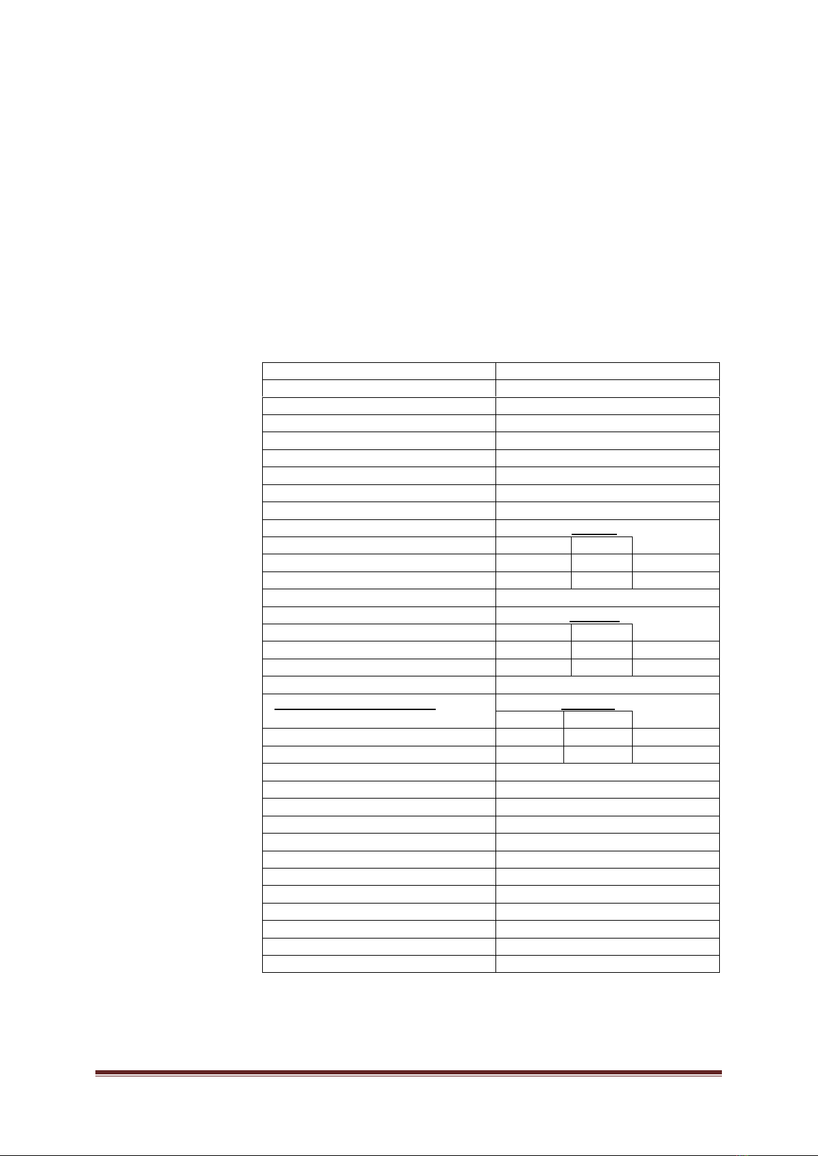
MODEL POWER MIG 210 LCD
GENERAL
POWER SUPPLY VOLTAGE 230V / 50Hz
POWER PROTECTION 20 And
CURRENT INTENSITY POWER 36 And
CURRENT INTENSITY POWER EFF. 16 And
VOLTAGE POWER IDLE 69 V
MIG WELDING PARAMETERS 40 -200 / 16- 24V 40 -200 / 16- 24V 40 -200 / 16- 24V
EFFICIENCY (at 40 ° C) 20% 60% 100%
Welding current 200A 115A 89A
Welding voltage 24V 19,7V 18,5V
MMA WELDING PARAMETERS 10-1 80A / 20,4- 27,2V 10-1 80A / 20,4- 27,2V 10-1 80A / 20,4- 27,2V
EFFICIENCY (at 40 ° C) 20% 60% 100%
Welding current 180A 104A 80A
Welding voltage 27,2V 24,1V 23,2V
TIG WELDING PARAMETERS LIFT 10 -180 / 10,4- 17,2V10 -180 / 10,4- 17,2V10 -180 / 10,4- 17,2V
EFFICIENCY (at 40 ° C) 20% 60% 100%
Welding current 180A 104A 80A
Welding voltage 17,2V 14,1V 13,2V
WIRE DIAMETER FE: 0.6-1.0 AL. and FLUX: 0.8-1.0
SIZE SPOOL 5 kg (200mm)
TYPE WIRE FEED 2-roll
arc ignition TOUCH
MODE HANDLE 2T / 4T
ELECTRODE DIAMETER 1.6 - 4.0
COOLING FAN
INSULATION CLASS H
DEGREE OF PROTECTION IP 21S
DIMENSIONS 73x32x48 cm
WEIGHT 21.5 kg

WELDMAN SEMI-AUTOMATIC LCD POWER MIG 210 MIG / MAG / MMA / TIG DC LIFT Page 4
IV. BUILDING
general view
Control Panel
Lp. Description Lp. Description
1 the left wheel: regulation of the welding current and pressing the control of wire feed speed 2 display 3
right wheel: voltage control welding current MIG / MAG 4
button to return to the first page of the display 5
the center knob: multifunction knob the menu (by pressing confirm selection) 6
button to return to the previous step
Item. Description
1 ground cable conduit mass 2 changes the polarity of the handle and the 1 ground cable conduit mass 2 changes the polarity of the handle and the
seat
The output of positive polarity or negative
3 euros socket welding torch 15 MB MIG / MAG, FLUX
4 control panel
5 type welding torch MB 15 AK

WELDMAN SEMI-AUTOMATIC LCD POWER MIG 210 MIG / MAG / MMA / TIG DC LIFT Page 5
V. INSTALLATION
Welder set on a flat and dry surface with a capacity suitable for the weight in order to avoid its overturning.
The device should be placed in a well ventilated area with free air circulation, away from flammable objects.
Make sure not enter the welder dust, corrosive vapors and moisture.
The unit should be set in such a place, not to get into it from welding spatter.
CONNECTING TO NETWORK
Before the electrical connection:
- check whether the data on the plate correspond to the values of the welding voltage and frequency of the network devices in the workplace
- check that the mains supply for the required input power
- check whether the fuse values are consistent with those given in the technical data
- Check the wiring grounding welding.
Welding wire is supplied with a 230V plug.
ELECTRICAL CONNECTION SHOULD BE CARRIED OUT BY QUALIFIED PERSONNEL OR EXPERIENCED
PREPARATION TO WORK:
1) welding machine before connecting to the network, make sure that the main switch on the rear 1) welding machine before connecting to the network, make sure that the main switch on the rear
the panel is in the OFF position
2) Flux for welding ( without cover gas) operating handle 15 MB AK fastened to the socket euros 2) Flux for welding ( without cover gas) operating handle 15 MB AK fastened to the socket euros 2) Flux for welding ( without cover gas) operating handle 15 MB AK fastened to the socket euros
(3) the reversal of the wire holder into the socket of the negative polarity (-), hollow clamp on the welded material and the plug ground
cable to the socket on the positive polarity (+)
3) MIG / MAG ( gas shield), an operating handle MB AK 15 are fastened to the EURO (3) 3) MIG / MAG ( gas shield), an operating handle MB AK 15 are fastened to the EURO (3) 3) MIG / MAG ( gas shield), an operating handle MB AK 15 are fastened to the EURO (3)
the reversal of the wire holder bay of positive polarity (+), hollow clamp on the welded material and the plug ground cable to the
socket on the negative polarity (-)
4) TIG LIFT WP plug of the control valve 26 to fix a socket 4) TIG LIFT WP plug of the control valve 26 to fix a socket 4) TIG LIFT WP plug of the control valve 26 to fix a socket
negative polarity (-), hollow clamp on the welded material and the plug ground cable to the socket on the positive polarity (+)
5) welding MMA hollow clamp are fastened at the welded material while the 5) welding MMA hollow clamp are fastened at the welded material while the 5) welding MMA hollow clamp are fastened at the welded material while the
connecting cables to the follow the instructions of the manufacturer of the electrodes: the most common plug wire from the electrode
holder fastened to the outlet of the positive polarity (+) and connect the ground cable to the socket of the negative polarity (-)
6) be prepared protective clothing (apron, boots and hood / welding helmet) 6) be prepared protective clothing (apron, boots and hood / welding helmet)
The above steps should be performed only when the welding device is disconnected from the power supply.
GAS CONNECTION TO WORK gas shielded MIG / MAG:
• gas cylinder secured against tipping
• Remove protection and for a moment to open the gas valve to remove debris
• gas regulator mounted on the bottle
• connect wire welder (rear exit gas) with a cylinder
• unscrew the gas valve before starting the welding and spin at the end of

WELDMAN SEMI-AUTOMATIC LCD POWER MIG 210 MIG / MAG / MMA / TIG DC LIFT Page 6
VI. WELDING
As soon as the welder is ready to go, we proceed to setting the operating parameters
MIG / MAG and FLUX
PREPARATION FOR WELDING
During preparation for work MIG / MAG after the general steps you should also follow the steps below:
welding torch
In the case of preparing a welder to work MIG / MAG welding torch before connecting to welding should pay attention to choosing the right
wire diameter, and then check whether it has been established the appropriate guide wire wire (FE: 0,6-0.8 wire blue wire, wire
1.0-1.2 red wire; AL .: 0.8 blue conductor wire, wire cable red 1.0) and the contact tip of the torch.
Installation Teflon liner for aluminum welding
holder Euro MIG / MAG:
AND. Remove the retaining nutAND. Remove the retaining nut
B. Pull the insert with a steel handleB. Pull the insert with a steel handle
C. Insert a Teflon liner for aluminumC. Insert a Teflon liner for aluminum
D. Install the mounting nutD. Install the mounting nut
E. It should be noted that the pad E. It should be noted that the pad
protrude from the holder so
that after insertion of the handle reached the wire
feed roller
Attaching the wire
• open the side cover welder
• ensure that the rollers in the dispenser are correctly attached and are in accordance with the diameter and the type of the wire
(steel wire - Roll V grooves, aluminum wires - the roller with grooves U)
• set up the spool of wire 200 mm (max 5 kg), and secured against falling (left-hand thread on the nut mounting spool)

WELDMAN SEMI-AUTOMATIC LCD POWER MIG 210 MIG / MAG / MMA / TIG DC LIFT Page 7
• cut off the deformed tip of the wire on the spool and round it
• release the pressure roller and insert the wire into the sleeve in back of the tray and the guide wire on the driving roller to a fitting,
welding torches
• reset the pressure roller and check if the wire is properly placed in the drive roller
•Remove gas nozzle and current nozzle out of the holder
• enable the welder, then press the trigger in the handle until the wire
•set up a current nozzle and the gas nozzle
• adjust the pressure adjustment knob and check that the wire does not slide in the groove
• close the side cover
SETTING THE PARAMETERS
Control Panel
As soon as the welder is ready to go, we proceed to set the operating parameters on the panel:
1. Welding mode selection screen 1. Welding mode selection screen
multipurpose knob (5) to select one of the function 9 (8
relates to a welding process and the Settings 1) by
pressing the knob (5) accept selection
2. External screen settings 2. External screen settings
It indicates the wiring, the composition of shielding
gas, depending on the welding method, and then
pressing the knob (5) accept selection
3. Diameter of said screen 3. Diameter of said screen
It allows you to select the correct
diameter of the electrode / wire,
pressing the knob (5) accept selection
4. Screen the thickness of the weld material 4. Screen the thickness of the weld material
to set the proper thickness of the welded material
pressing the knob (5) accept selection

WELDMAN SEMI-AUTOMATIC LCD POWER MIG 210 MIG / MAG / MMA / TIG DC LIFT Page 8
5. Screen welding parameters 5. Screen welding parameters
and) MIG / MAGand) MIG / MAG
the operator can adjust the speed of feeding a wire (1) and welding voltage (3), the inductance (5) by pressing the knob and
rotating can change the underlying operating parameters: pre-gas and wire feed post gas, operation of the handle (2T / 4T /
welding point), set and save the operating parameters and settings spool gun for welding aluminum Green field indicates the
recommended range of welding current
b) TIG weldingb) TIG welding
the operator can adjust the welding current
c) welding MMA
the operator can adjust the welding current, Arc Force
and Hot Start
6. Screen factory settings 6. Screen factory settings
It enables reading settings (language, parameters, brightness
information) and return to factory settings
7. alarm screen 7. alarm screen
inform the overloading and excessive temperature inside the welder.
The welding process is automatically stopped, but the fan will run.
When the temperature decreases, the screen turns off the alarm and
the welder is ready for use.

WELDMAN SEMI-AUTOMATIC LCD POWER MIG 210 MIG / MAG / MMA / TIG DC LIFT Page 9
WELDING (MIG)
• turn on the main switch on the rear panel of the welder
•unscrew the valve on the gas cylinder, and set the appropriate gas flow to the pressure regulator
•We set the wire feed speed (1) and the desired voltage value of the welding current (2)
• we start welding
• after welding turn off the gas valve on the cylinder
• after welding leave the machine turned on for a short period of time the aim of cooling fan
WELDING (FLUX)
• turn on the main switch on the rear panel of the welder
•We set the wire feed speed (1) and the desired voltage value of the welding current (2)
• we start welding
• after welding leave the machine turned on for a short period of time the aim of cooling fan
•remove slag from the weld
MMA WELDING METHOD
PREPARATION FOR WELDING
ARC FORCE (PRESSURE ARC)
ARC FORCE involves shortening the arc with an increase in the value of the welding current. This allows easier ignition of the arc when
welding starts and keeping it in operation. Optimizes the transmission drops from the electrode material, preventing the extinguishing of the
arc in the case of contact electrodes with welded material.
Controls ARC FORCE (pressure of the arc):
turning the right knob to adjust Arc Force 0-10 for electrodes: minimum value - the value of the central
electrode rutile - basic electrode maximum values - cellulosic electrodes
ARC HOT (HOT START)
Hot Start increases the value of current at the arc start to heat the material and the electrode, which optimizes the process.
ANTI STICK (prevents adhesion)
Function is to reduce the welding current by preventing sticking of the electrode to the work piece during arc start and heats it at the time of
sticking. An important feature for inexperienced operators.
WELDING (MMA)
• After wiring Let us welding device
• We set a desired value of welding current (1)
• We start welding maintaining appropriate work rules
• after welding leave the machine turned on for a short period of time the aim of cooling fan
• We remove the weld slag

WELDMAN SEMI-AUTOMATIC LCD POWER MIG 210 MIG / MAG / MMA / TIG DC LIFT Page 10
TIG welding
PREPARATION FOR WELDING
Cleaning before welding
TIG welding is very sensitive to surface contamination of the metal. Because of that, before the welding process must be removed from the
surface of the welded lubricants, paints, coatings and oxidized.
Welding - arc ignition (touch)
1) Welding starting end should touch the surface of the tungsten electrode welded, by pressing the trigger in the handle TIG and
increasing the distance 2-3mm will touch arc ignition (LIFT ARC)
2) The value of the welding current is increased to a set value 2) The value of the welding current is increased to a set value
3) We raise and rotate the handle to the normal working height
4) Completion of the work takes place by lifting the handle until the extinction of the arc
VII. POTENCE Irregularities in Jalna WORK Y: POTENCE Irregularities in Jalna WORK Y: POTENCE Irregularities in Jalna WORK Y:
symptoms Cause Procedure
The yellow LED lights up
The voltage is too high (≥15%) Turn off the power, check the installation and restart the welder
when the supply voltage is in the proper condition
The voltage is too low (≤15%)
Poor ventilation thermal protection Increase ventilation
Too high temperature circuit Indicator automatically turns off when the
temperature decreases
Using more than the recommended load
Lack of a wire (feeder motor is
running)
For poorly tightened pressure Tighten the clamp correctly
Contaminated guide wire holder Clean the wire guide
A predetermined groove roll does not correspond to the
diameter of the wire
Brought into line with the roll diameter and wire
Blocked the wire in the nozzle current Replace the current nozzle
No wire feed (feed motor not
running)
Damaged engine Pass the welder to the site
Faulty control system Pass the welder to the site
Irregular wire feed
Current defective nozzle Replace the nozzle current on new
The groove feeding roller is dirty, damaged
or not the diameter of the wire Replace the roll or roller to choose the diameter of the
wire used
Not to bow strikes Lack of proper contact wire clamp
mass Improve contact terminal
Arc too short Welding voltage too low Increase welding voltage
Wire feed speed too high Reduce the wire feed speed
Arc too long and
irregular
Welding voltage too high Reduce the welding voltage
Wire feed speed too low Increase the speed of wire feed

WELDMAN SEMI-AUTOMATIC LCD POWER MIG 210 MIG / MAG / MMA / TIG DC LIFT Page 11
VIII. RECOMMENDED WELDING
for carbon steels using a mixed gas (82% Ar / 18% CO₂) for carbon steel using CO₂
gas (100% CO₂) for stainless steel using a mixed gas (98% Ar / 2% CO₂)
IX. MAINTENANCE
Before maintenance, disconnect the welding device from the mains and allow to cool handle. Maintenance work daily:
- check the welding cables and connections
- check and clean the wire feed roller
- check the status of consumables (gas nozzle, the nozzle current)
- replace worn or damaged parts of the monthly
maintenance operations:
- clean the inside of compressed air welder
- check the electrical connections inside the welder
- check items related to the wire feeding

WELDMAN SEMI-AUTOMATIC LCD POWER MIG 210 MIG / MAG / MMA / TIG DC LIFT Page 12
X. WARRANTY:
The manufacturer guarantees the correct functioning of the equipment and is committed to the free exchange of parts that spoil as a
result of poor quality material or manufacturing defects within 12 months from the launch date equipment, certified warranty. The cost of
sending the unit to the manufacturer and the manufacturer to the user during the warranty period covers the user device.
Devices that have been sold in EU member states as consumer goods, are covered by the 24 month warranty period, the cost of
sending the unit to the manufacturer and the manufacturer to the user during the warranty period covers the device manufacturer in accordance
with the European Directive 1999/44 / EC. The warranty card is only valid if accompanied by a receipt or purchase invoice. Difficulties arising
from misuse, negligence or breach of the device are not covered by the warranty. The manufacturer is not liable for any direct or indirect
damages.
Warranty Card.
Model:
no:
Sale date: Dealer:
DELKARACJA CONFORMITY
Importer DELTA-TECH Sp. z oo with its seat in Lublin Street Stanislaw Lem 26 on the basis of the declaration of the manufacturer,
declare with full responsibility that the device complies with the following directives: EN 60974-1: 2012 LVD 2014/35 / EU, the EMC
2014/30 / EU
The symbol, which means sorting of waste electrical and electronic equipment. It is forbidden to
suppress the equipment as mixed municipal solid waste, the responsibility of the user is directed
to an authorized waste collecting centers.
Table of contents
Other Weldman Welding System manuals
Popular Welding System manuals by other brands

Lincoln Electric
Lincoln Electric PF44 Operator's manual

Cebora
Cebora POWER SPOT 5700 instruction manual

Victor
Victor CUTMASTER A40 operating manual

EWM
EWM MT221-301G F2 operating instructions

Lincoln Electric
Lincoln Electric HANDY MIG IM756-A Operator's manual

Zenit Powertools
Zenit Powertools MMA-200/2 instruction manual

Costway
Costway ET10011US user manual

WELDKAR
WELDKAR WK TIG 2025 AC/DC Pulse instruction manual

Cebora
Cebora WIN TIG DC 220M instruction manual

MasterCraft
MasterCraft WG2063 Operating instructions & parts manual

CEMONT
CEMONT SPEEDY 130 Safety instruction for use and maintenance

Leister
Leister GEOSTAR G5 LQS operating instructions