WeldTec C25 STANDARD User manual

TEC WELDING PRODUCTS, INC.
P.O. Box 1870 •San Marcos, CA 92079 •Phone 760-747-3700
www.tectorch.com www.weldtec.com
WATER COOLING SYSTEMS
OWNER’S MANUAL
C45
C35
C45
PREMIUM -DUAL COOL (4 Gallon)
C35
DELUXE (3 Gallon)
C25
STANDARD (2 Gallon)
MODEL C25 STANDARD
C35 DELUXE
C45 PREMIUM -DUAL COOLTM

TEC WELDING PRODUCTS, INC.
P.O. Box 1870 •San Marcos, CA 92079 •Phone 760-747-3700
www.tectorch.com www.weldtec.com
1) INTRODUCTION
1.1 DESCRIPTION
The WeldTec®water cooling systems are
designed for cooling TIG, MIG and plasma
welding and cutting torches. The systems may
also be used for other cooling applications
such as spot welding equipment, casting
equipment, induction heating equipment, etc.
Check BTU rating needs for other applications.
The cooling systems are built using proven
industrial quality components designed to
give long trouble free performance.
1.2 FEATURES
The units consists of a stainless steel tank,
pump, motor, high volume cooling fan and
aluminum finned radiator. The pump draws
water from the tank sending it to the equipment
to be cooled. The returning water is discharged
bank into the tank for recirculation.
All units are available with an optional gear
pump with a built-in bypass which returns the
excess pump output back to the tank. This
keeps the pump cool and provides longer
pump life.
The clear fill port allows the operator to see
the coolant flow while the unit is operating.
A filter is located in the pick up hose to help
prevent debris from damaging the pump.
1.3 SAFETY
CAUTION -Read and understand the operation
manuals for all equipment being used with
the cooler unit.
The installation and maintenance of this
equipment must by done by qualified -
knowledgeable persons only.
IMPORTANT -The operating voltage, phase
and frequency is marked at thefront of the
unit. Only connect the unit to the voltage
indicated. For 115 volt service use the
grounded 115 volt 3 prong plug provided.
DO NOT remove the ground prong. The 230
volt unit is not shipped with a plug. Install an
appropriate grounded plug. This connection
should be made by a qualified electrician.
2) INSTALLATION
Inspect the shipping carton and cooler unit
for any shipping damage. Shipping damage
claims must be made with the delivering carrier.
2.1 HOSE CONNECTIONS
Connect the welding equipment hoses to the
"water to torch" and "water return" connections.
The "water to torch" connection is the output
line from the pump. The "water return" connection
is the return line from the welding / cutting
equipment back to the tank.
DO NOT use a water on-off solenoid valve
on the power supply if there is one provided.
The water / coolant must flow through the
equipment continuously while it is being used
and during idle periods. Be sure all connections
are snug but avoid over tightening. Welding
connections are self sealing and do not require
Teflon tape to seal.
2.2 FILLING THE TANK
Remove the cover of the fill port and fill the
tank with the EXACT number gallons for the
specific model. DO NOT OVER FILL. Water
or coolant warms up as it is used to cool the
equipment and will expand, if over filled, the
expanding fluid will leak out the top of the tank.
Only use distilled, deionize water or special
coolant. DO NOT -use tap water or well water.
Replace filler cap, check all connections
and test run the unit for several minutes.

DO NOT OPERATE THE COOLER UNIT
WITH THE COVER REMOVED.
ELECTRICAL SHOCK CAN KILL,
MOVING PARTS CAN CAUSE
SERIOUS INJURY.
TEC WELDING PRODUCTS, INC.
P.O. Box 1870 •San Marcos, CA 92079 •Phone 760-747-3700
www.tectorch.com www.weldtec.com
If the cooler will be used in freezing
conditions a non-automotive anti-freeze
should be added. Follow the anti-freeze
directions for proper mixture based on the
lowest expected temperatures. Automotive
anti-freeze contains additives which will harm
the pump, lines and equipment causing
permanent damage. Use of automotive
anti-freeze voids the cooler warranty.
Propylene glycol type anti-freeze is
recommended for safety reasons.
3) OPERATION
ADJUSTABLE PUMP PRESSURE
The pump is equipped with an adjustable
pressure screw. The factory setting is 50 psi
which will yield 1.7 gpm of flow. Some
equipment may require higher pressure
settings. Consult the manufacturers guidelines
for maximum pressure ratings. To adjust
the pressure setting unplug the cooler, locate
the adjusting screw on the side of the pump.
Turning the adjusting screw clockwise will
increase the output pressure and counter
clockwise will decrease the output pressure.
A pressure test gauge should be used to
accurately set the output pressure. Do not
exceed the maximum pressure rating for the
equipment being cooled. CAUTION -most
welding equipment requires flow volume, not
high pressure for proper cooling. Check the
flow requirements of the equipment being
cooled for the proper fluid flow needs.
4) MAINTENANCE
CAUTION -Do not attempt any repairs or
maintenance while the unit is connected
to the input power supply. Unplug the unit
before making any adjustments or repairs.
Consult the equipment manuals for
maintenance instructions for that specific
equipment.
Keep the unit clean and free from accumulated
dust and debris. Blow off the unit and radiator
fins with compressed air every six months or
more frequently if needed. If the unit is fitted
with a dust filter, blow off and wash the filter
in soapy water, rinse, dry and replace.
To replace the coolant, pump all coolant from
tank and flush with clean water. Flush out the
torch lines at the same time. Replace the
coolant, distilled, or deionize water and fill
with the exact gallons required for the tank
size. Replace coolant yearly. Check all lines
and hose clamps and adjust or replace as
needed.
The gear type pump will give long trouble free
service. Pump wear is noticeable by a decrease
in output pressure or flow rate. The wear will
usually take place over a lengthy period
allowing time to make repairs or replace the
pump before complete failure occurs. A repair
kit is available for field repair that contains
internal pump gears, seals, etc. The entire
pump can be quickly changed by means of
the clamp connection.
The vane type pump will fail if the internal
vanes are chipped or broken by debris in
the lines, usually without warning. It is not
field repairable, so a spare pump will save
down time and can be quickly changed if
unexpected failure occurs.
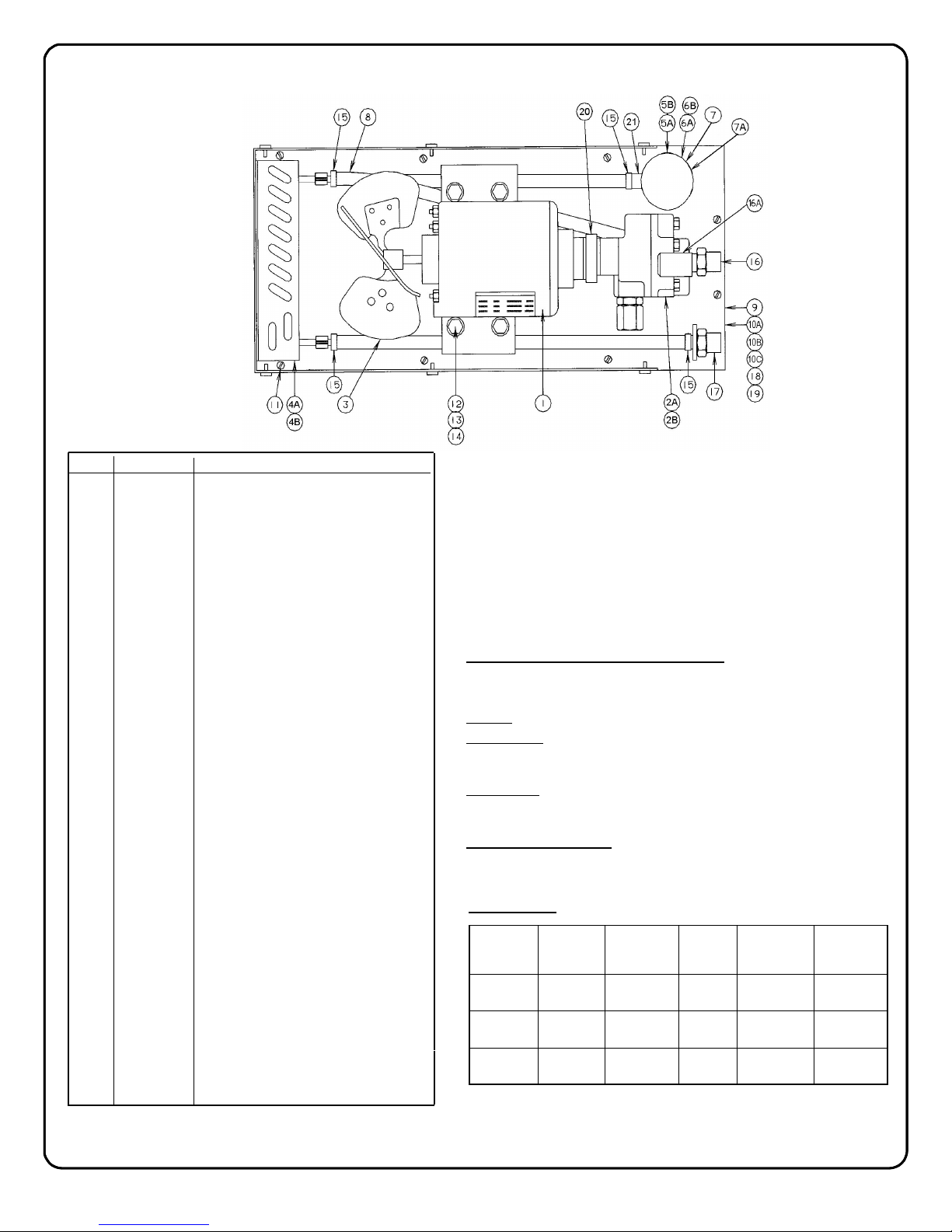
When ordering spare or replacement parts be
sure to give the cooler model, item part number
and complete description of the parts required.

Model Data:
SPECIFICATIONS
REVISION H
MODEL
MOTOR
INPUT
VOLTAGE
AMPERES
INPUT
FULL LOAD PHASE
FREQUENCY
(HZ)
COOLANT
TANK
CAPACITY
C25 115V 5.6 Single 50/60 2.0 gals
C35 115V 5.6 Single 50/60 3.0 gals
C45 115V 5.6 Single 50/60 4.0 gals
Pump Specifications and Capacity:
Factory pressure setting 50 PSI, adjustable 2-100 PSI.
Built-in bypass to tank (gear pump only).
Output: 1.7 gallons per minute @ 50 PSI.
Dimensions: C25 18” L x 9 1/4” W x 12 1/2” H.
C35 18” L x 9 1/4” W x 14” H.
C45 18” L x 9 1/4” W x 16” H.
Dry Weight: C25 Net 31 lbs.
C35 Net 33 lbs.
C45 Net 35 lbs.
Torch/gun connections:
Standard: 5/8-18 LH water adapter.
ITEM PART NO. DESCRIPTION
1C 3000
2A C 1110
2B C 102RP-V
N/S C 11969
3C 3075
4A C 0900-2
4B C 0900-3
5AC 1502-1
6AC 1502
8C 0904
9C 0901-1
10A C 0905-1
11 C 1000
12 C 1001
13 C 1003
14 C 1004
15 C 0903
16 C 1005
18 C 1006
19 C 1007
20 C 3003
21 C 1502-3
N/S C 1012
N/S C 1008
N/S C 1010
N/S C 0902
N/S C 1011
N/S C 3007
N/S C 3008
10C C 0905-2
10B C 0905-3
N/S C 0902-1
16A C 1005A
17 C 1002
COPYRIGHT 2013 - 2018SPECIFICATIONS SUBJECT TO CHANGE WITHOUT NOTICE.
TEC WELDING PRODUCTS, INC.
P.O. Box 1870 •San Marcos, CA 92079 •Phone 760-747-3700
www.tectorch.com www.weldtec.com
N/S - Not Shown
PARTS DIAGRAM
Cooling System
Electric Motor 1/3 HP 115/230V-50/60 Hz
Gear Pump - Oberdorfer (Optional)
Vane Pump - WeldTec® (Standard)
Gear Pump Repair Kit
Fan
Radiator Coil Unit C25, C35
Radiator Coil Unit C45
Fill Port Cap (Push On Cap)
Fill Port (Push On Cap Port)
Cap Retaining O-ring (Push On Cap)
Fill Port Cap (Screw On Cap)
Fill Port (Screw On Cap Port)
Fill Port Mounting O-ring (Both)
Hose, 3/8 I.D. typ.
Top Plate
Stainless Steel Tank C25
Stainless Steel Tank C35
Stainless Steel Tank C45
Sheet Metal Screw
Hex Bolt
Flat Washer
Nut
Stainless Steel Hose Clamp
Water Adapter
3/8 Street Elbow 90°
Hose Nipple
Tank Gasket
Tank Feet Pads (4 Pack)
Clamp (Gear Or Vane Pump)
Nylon Hose Nipple
Plastic Parts Storage Box (C35 Only)
Strainer - Pick Up Hose
Power Cord and Plug 115V-60Hz
Stainless Steel Cover
Hose Barb - 3/8
Coupling Key (Gear Pump)
Coupling Key (Vane Pump)
Plastic Grill
C 1503-1
C 1503
5B
6B
C 1502-2
7A
7C 1503-5
This manual suits for next models
2
Table of contents