2
Powerline Ethernet Adaptor
Chapter 2 – Installation & Uninstallation
Connection of Powerline Ethernet Adapter
2.1 Installing Powerline Device
1. If you have the SINGLE PACKAGE of Powerline,Connect the supplied RJ45 Ethernet cable
from your PC's Ethernet port to the Powerline Ethernet Adapter's LAN Ports or connect the
supplied RJ45 Ethernet cable from your xDSL/Cable Modem's Ethernet port to the Powerline
Ethernet Adapter's LAN Ports.
2. If you have the TWIN PACKAGE of Powerline, connect the supplied RJ45 Ethernet cable
from your PC's Ethernet port to the Powerline Ethernet Adapter's LAN Ports and connect the
supplied RJ45 Ethernet cable from your xDSL/Cable Modem's Ethernet port to the Powerline
Ethernet Adapter's LAN Ports.
3. Connect the Powerline Ethernet Adapter to your wall-mounted power outlet.
4. Check if the PLC LED of Powerline Ethernet Adapter is ON, the Powerline Ethernet Adapter
is connected and suitable for Internet Connections.
5. Check if the PLC LED is OFF, the Powerline Ethernet Adapter isn’t connected and suitable
for Internet Connections. Please follow next step to have it connected and suitable for
Internet Connections.
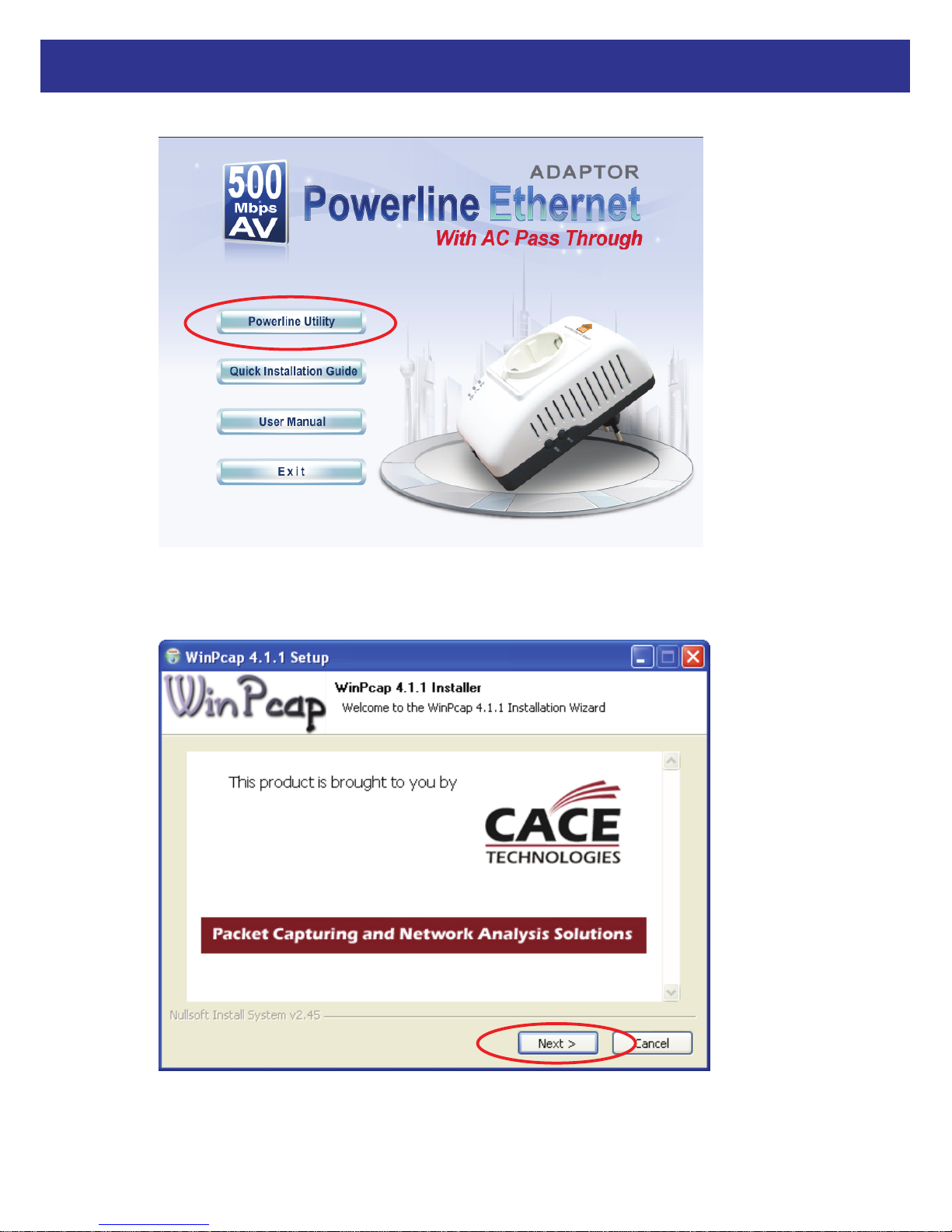
2.2 Installation of Powerline Utility
The Configuration Utility enables the users to identify HomePlug devices on the Powerline
network, measures data rate performance, ensures privacy and performs diagnostics by setting
user defined secure Powerline networks.
Users are requested to verify that no other Encryption Management Utilities are installed prior to
the installation of this utility. Other utilities should be uninstalled before installing this utility.
1. In order to install, insert Configuration Utility CD-ROM into the computer’s CD-ROM drive.
The program shall run automatically. Alternatively this can also be done manually by double
clicking the autorun.exe file on the CD.