manuals.online logo
Brands
  1. Home
  2. •
  3. Brands
  4. •
  5. Wellborn Cabinet
  6. •
  7. Indoor Furnishing
  8. •
  9. Wellborn Cabinet SSDSC User manual

Wellborn Cabinet SSDSC User manual

Wellborn Cabinet, Inc. • 38669 Hwy. 77 • Ashland, AL 36251 • Phone (256) 354-7151 • FAX (256) 354-7022
InstallatIon InstructIons
24” Deep SSDSC & SSDSCDVD
KIT INCLUDES:
(1) Dovetail Sliding Shelf or CD/DVD Sliding Shelf
(4) B7905 – #8 x 5⁄8 Truss Head Screws
(1) C2183 – Set of Full Extension Soft Close Slides
(8) B7934 – 11.5mm Euro Screws
(4) C2312 – SS Brackets
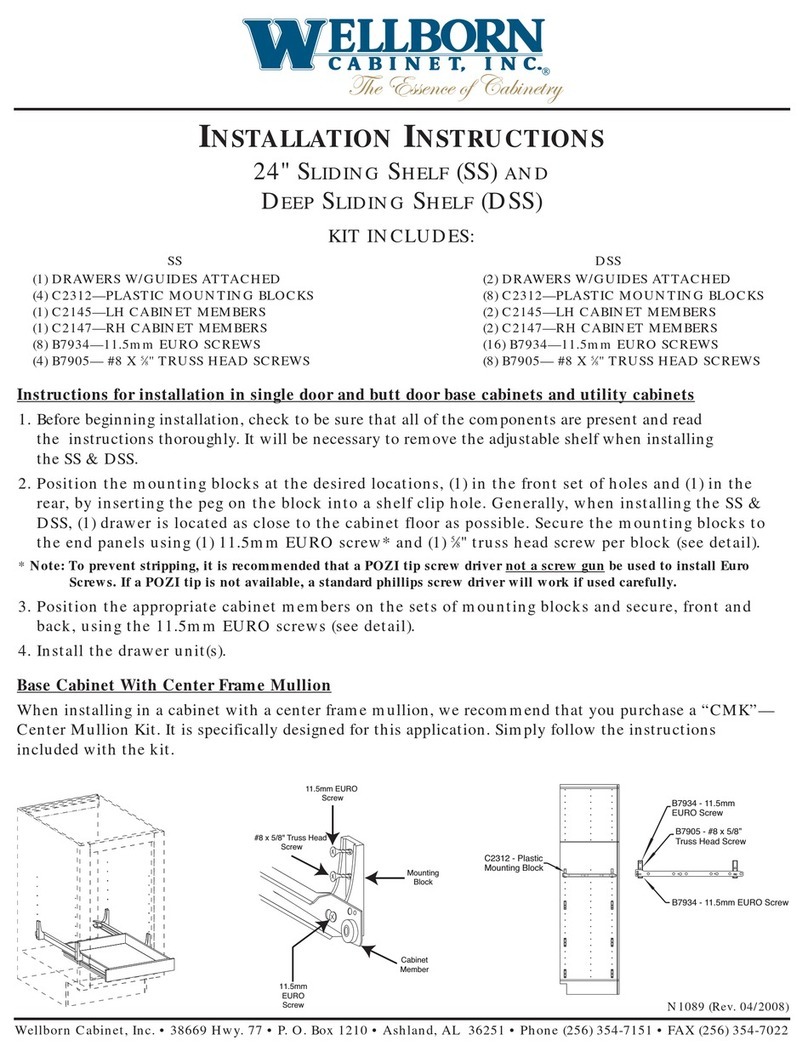
Instructions for Single Door & Butt Door Base & Utility Cabinets
Installing the drawer slides:
1. Before beginning installation, check to be sure all components are present and read the
instructions thoroughly. If you are installing multiple Sliding Shelves it may be necessary
to remove or relocate any adjustable shelves that are installed in the cabinet.
2. Install the (4) SS Brackets at the desired locations inside the cabinet. This is accomplished
by placing the peg on the back of the SS Bracket into the shelf pin hole at the desired
location and installing an 11.5mm Euro screw* through the top hole in the bracket and into
the corresponding shelf pin hole.
* Note: To prevent stripping, it is recommended that a POZI tip screw driver not a screw gun be used to install
Euro Screws. If a POZI tip is not available, a standard phillips screw driver will work if used carefully.
3. Complete installation of the SS Brackets by installing a #8 x 5⁄8 truss head screw through the
center hole of each bracket and into the cabinet end panel.
4. Attach the Full Extension Drawer Guides to the SS Brackets at the appropriate location by
holding each guide in place and installing an 11.5mm Euro screw through the hole in the
guide and into the lower hole in the SS Bracket. For best results, it is recommended that
you utilize the 4th hole from the front and the last hole at the rear in the lower row of holes
(see diagram below).
Installing the SSDSC or SSDSCDVD Sliding Shelf:
5. Start by pulling each Drawer Guide about ½ – 2⁄3 of the way out. Place the Sliding Shelf on
top of the guides leaving about 4” between the back of the Sliding Shelf and the “hook” at
the rear of the guide.
6. Close the Sliding Shelf allowing it to slide on top of the guides so that the locking
mechanisms located on the under side of the Sliding Shelf engage the front of the guides
and the “hooks” at the rear of the guides go into the holes in the rear of the Sliding Shelf.
It is essential that these connections be made so that the Sliding Shelf is supported and
functions properly.
See CMK (Center Mullion Kit) Installation Instructions on back. N1523 (Rev. 08/2011)
Wellborn Cabinet, Inc. • 38669 Hwy. 77 • Ashland, AL 36251 • Phone (256) 354-7151 • FAX (256) 354-7022
N1523 (Rev. 08/2011)
24” Deep SSDSC & SSDSCDVD
InstallatIon InstructIons (continued)
Instructions for Base Cabinets with Center Frame Mullion
When installing the SSDSC or SSDSCDVD Sliding Shelf in a base cabinet with a center frame mullion, it is
recommended that you purchase a “CMK” Center Mullion Kit. The “CMK” is specifically designed for this
application. Follow the instructions with the “CMK” to install it inside the cabinet directly behind the frame
center mullion then follow the instructions for installing the Sliding Shelves.
Center Mullion Kit (CMK) Installation Instructions
Locate (2) Top/Bottom Plates and determine the front of each by checking the distance from the end to the
groove. It is approximately 1½” from the front to the edge of the groove.
Assemble the framework by inserting the ends of the Vertical Sticks into the grooves in the Top/Bottom Plates
and installing (4) screws into the predrilled holes located in each end of the Top/Bottom Plates.
Determine the location for each rollout and follow the instructions included with the kit for installing the
C2312 Rollout Brackets and the drawer slide cabinet members to the cabinet end panels and the Center
Mullion Kit. The C2312 Rollout Brackets
and drawer slides should now be installed
on the interior of the cabinet end panels and
in corresponding locations on the Center
Mullion Kit framework.
Position the Center Mullion Kit assembly in
the center of the cabinet directly behind the
cabinet frame mullion. DO NOT FASTEN
TO THE FLOOR AT THIS TIME.
Install a rollout on each side of the Center
Mullion Kit. This will center the kit in
the cabinet. Hold the Center Mullion Kit
in place while operating each rollout to
make sure they function properly. With the
rollouts in the retracted position, fasten the
framework to the floor of the cabinet using
(2) #8 x 1¼” screws.
B7923
#8 x 1 1/4
Flat Phillips Hd.
(4) req'd
Vertical
stick
Top/Bottom Plate
B7923 - #8 x 1 1/4
Flat Phillips Hd.
(2) req'd
C2312 Rollout Bracket
Included with Shelf Kits
Front is longer
than back (approx. 1 1/2")
Parts List
(2) Top/Bottom Plate
(2) Vertical Stick
(6) B7923 - #8 x 1 1/4 FPH Screw
Instructions:
Locate (2) Top/Bottom Plates and determine the front of each by checking the distance from the end to the groove. It is approximately 1 1/2"
from the front to the edge of the groove.
Assemble the framework by inserting the ends of the Vertical Sticks into the grooves in the Top/Bottom Plates and installing (4) screws into the
predrilled holes located in each end of the Top/Bottom Plates.
Determine the location for each rollout and follow the instructions included with the SS Kit for installing the C2312 Rollout Brackets and the
drawer slide cabinet members to the cabinet end panels and the Center Mullion Kit.
The C2312 Rollout Brackets and drawer slides should now be installed on the interior of the cabinet end panels and in corresponding locations
on the Center Mullion Kit framework.
Position the Center Mullion Kit assembly in the center of the cabinet directly behind the cabinet frame mullion. DO NOT FASTEN TO THE
FLOOR AT THIS TIME.
Install a rollout on each side of the Center Mullion Kit. This will center the kit in the cabinet. Hold the Center Mullion Kit in place while operating
each rollout to make sure they function properly. With the rollouts in the retracted position, fasten the framework to the floor of the cabinet using
(2) #8 x 1 1/4" screws.
Top/Bottom
Plate

This manual suits for next models

1

Other Wellborn Cabinet Indoor Furnishing manuals

Wellborn Cabinet ESTATE series Assembly instructions

Wellborn Cabinet

Wellborn Cabinet ESTATE series Assembly instructions

Wellborn Cabinet DSS User manual

Wellborn Cabinet

Wellborn Cabinet DSS User manual

Popular Indoor Furnishing manuals by other brands

LOEHR L2 ENO Assembly instructions

LOEHR

LOEHR L2 ENO Assembly instructions

realspace Magellan Performance 216-230 Assembly instructions and warranty information

realspace

realspace Magellan Performance 216-230 Assembly instructions and warranty information

fantastic furniture Twilight manual

fantastic furniture

fantastic furniture Twilight manual

ThunderDog TCE15 Assembly instructions

ThunderDog

ThunderDog TCE15 Assembly instructions

LDI Safco Anywhere 5090 Assembly instructions

LDI

LDI Safco Anywhere 5090 Assembly instructions

Suncast BMSASHELFK1 Assembly instructions

Suncast

Suncast BMSASHELFK1 Assembly instructions

Lorell LLR68569 manual

Lorell

Lorell LLR68569 manual

Costway HY10039 user manual

Costway

Costway HY10039 user manual

Monarch Specialties I 1872 Assembly instruction

Monarch Specialties

Monarch Specialties I 1872 Assembly instruction

DURAVIT N1 4267 Mounting instructions

DURAVIT

DURAVIT N1 4267 Mounting instructions

Philips Ledino 57923/48/16 Specifications

Philips

Philips Ledino 57923/48/16 Specifications

LF Style Selections 8865GYMV manual

LF

LF Style Selections 8865GYMV manual

stackAshelf Storage Cabinet PSC24 instruction sheet

stackAshelf

stackAshelf Storage Cabinet PSC24 instruction sheet

Next 179793 Assembly instructions

Next

Next 179793 Assembly instructions

Costway HV10471 manual

Costway

Costway HV10471 manual

Abt SDAV1 5031 Assembly instructions

Abt

Abt SDAV1 5031 Assembly instructions

Restol Thea AHW-1P Fitting-Up Instruction

Restol

Restol Thea AHW-1P Fitting-Up Instruction

Sanus Systems F32A-S1 Brochure & specs

Sanus Systems

Sanus Systems F32A-S1 Brochure & specs

manuals.online logo
manuals.online logoBrands
  • About & Mission
  • Contact us
  • Privacy Policy
  • Terms and Conditions

Copyright 2025 Manuals.Online. All Rights Reserved.