manuals.online logo
Brands
  1. Home
  2. •
  3. Brands
  4. •
  5. WESLOCK
  6. •
  7. Indoor Furnishing
  8. •
  9. WESLOCK Molten Bronze 7625 User manual

WESLOCK Molten Bronze 7625 User manual

INSTRUCTIONS FOR INSTALLING YOUR WESLOCK PRODUCT
PARTS INCLUDED
REQUIRED TOOLS
SCAN THE CODE FOR
INSTALATION VIDEOS
GLOSSARY OF TERMS
Wood Screws (x8)
Molten Bronze Collection
Please reference www.weslock.com for the most current instructions.
Entry Handle Set
7625 & 7925 Collection
Do not insert key, or unlock handle before installation. Doing so may result in removal of the cylinder assembly.
Technical language used in this document
For mounting strikes & faceplates.
Measuring Tape
Or other measuring tool
Screwdriver
Phillips and flat blade
Wood Chisel
*Only if prepping a new door
Writing Utensil
*Only if prepping a new door
DOOR PREP INSTRUCTIONS 2 WESLOCK.COM
Interior Knob/Lever
Assembly
Interior knob / lever, rosette
& spindle.
XL 3” Wood Screws (x2)
For mounting strike (optional).
MORTISE
Entry Keys (x2)
For unlocking
the deadbolt.
Deadbolt Latch
Engages strike with door closed.
Strikes (x6)
Install on door frame.
Interior Deadbolt
Assembly
Exterior Deadbolt
Assembly
Exterior Grip Assembly
Exterior handle & thumb piece.
Assembly Screws (x2)
For mounting interior deadbolt
assembly. 3”
Foot Screw Cap Assembly
Faceplates (x4)
For covering a mortise latch.
* Only use one (1-3/4” 0R 2-1/4”)
screw based on thickness of door.
Iron Door Latch Casing
* Slide over thumbpress latch for
iron door application.
MORTISE
Thumb Press Latch
MORTISE
Engages strike with door closed.
Assembly Screws (x2)
Pre-installed on Exterior Grip Assembly
for mounting interior knob / lever
assembly. 1-1/4”
CROSS BORE
EDGE BORE
THUMB PRESS LATCH
DEADBOLT LATCH
* For Non-Mortise applications
see below parts.
* For Non-Mortise applications
see below parts.
* For Non-Mortise applications
see below parts.
FACEPLATES (X4) DEADBOLT LATCH THUMB PRESS LATCH
* Non-Mortise (Drive-In) Application
NON-MORTISENON-MORTISE
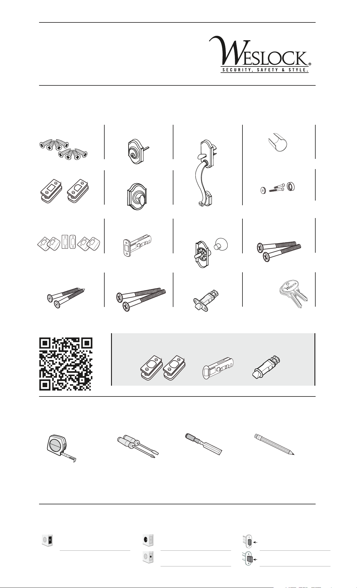
IDENTIFY THE LATCH TYPE FOR YOUR DEADBOLT AND THUMBPRESS LATCH
This will determine how you install the latch assembly in section 7.
DETERMINE THE BACKSET OF YOUR DEADBOLT LATCH AND THUMBPRESS LATCH
The length of your latch assembly will be determined by your backset measurement.
To change right or left hand setting (factory setting is right hand) of the exterior side of the entry
handle. The nylon block must be installed and is required for proper functionality of spindle.
MORTISE
ADJUSTING THE HANDING OF YOUR ENTRY HANDLE
MEASURE THE DOOR IF MEASUREMENT = 23/8”
Latch leaves the factory with this setting.
No adjustment is necessary.
KEEP
ADJUSTMENT
PIN IN PLACE
GRASP ADJUSTMENT
PIN ON BOTH SIDES
LIFT UP AND SLIDE
BACK TO 2-3/4” SLOT
1
1
2
Slide adjustment pin back to 23/4”slot.
Measure distance between center of
crossbore and edge of door.
IF MEASUREMENT = 23/4”
*Adapted
BACKSET LENGTH CENTER
LINE
Measure distance between center of
crossbore and edge of door.
BACKSET LENGTH CENTER
LINE REMOVE EXTENSION KEEP EXTENSION IN PLACE
No adjustment is necessary. Leave
extension attached to latch assembly.
Pry extension to remove it from the latch
assembly, using a at blade screwdriver.
B. Replace Spindle & Nylon BlockA. Remove Nylon Block & Spindle
CShaped Steel Spindle
Black Nylon Block
Using a screwdriver, slide the nylon block
out of it’s channel and remove from assembly.
With thumb and forefinger grab spindle, pull up
and rotate 180°.
238
/234
/
238
/234
/238
/234
/
238
/234
/
STEP 1 STEP 2
Reinsert nylon block on opposing side of
assembly, adjacent to repositioned spindle.
STEP 3
MORTISE
NO MORTISE
NO MORTISE
LATCH
ASSEMBLY
LATCH
ASSEMBLY
LATCH
ASSEMBLY
FACEPLATE
MORTISE
LATCH
ASSEMBLY
FACEPLATE
MORTISE
NO MORTISE
NO MORTISE
LATCH
ASSEMBLY
LATCH
ASSEMBLY
LATCH
ASSEMBLY
FACEPLATE
MORTISE
LATCH
ASSEMBLY
FACEPLATE
MORTISE
NO MORTISE
NO MORTISE MORTISE
SNAP-ON
FACEPLATE
LATCH
ASSEMBLY
LATCH
ASSEMBLY
LATCH
ASSEMBLY
LATCH
ASSEMBLY
FACEPLATE
MORTISE
LATCH
ASSEMBLY
FACEPLATE
MORTISE
SNAP-ON
FACEPLATE
LATCH
ASSEMBLY
Deadbolt latch must be extended prior to installation.
INSTALLATION
PUSH FIRMLY ON
KNOB/LEVER TO
INSTALL
2
REMOVE LOCK
SCREWS PRIOR
TO INSTALL
1
7B. Insert Non-Mortise Latches 7C. Install Exterior Deadbolt and
Grip Assemblies
A.
Insert deadbolt
tailpiece into cam
in deadbolt latch.
B.
Align notches on
grip housing with
proper grooves
(2-3/8 or 2-3/4) on
latch. Slide on.
At same time,
align and insert
foot screw
through
pre-drilled hole.
7D. Install Interior Deadbolt and
Knob/Lever Assemblies
7E. Install Strikes
7A. Insert Mortise Latches
WESLOCK WARRANTY INFORMATION
WESLOCK warrants to the purchaser that the products shall be free from defects in material workmanship for the LIFETIME of the product.
Provided the product was purchased from an authorized WESLOCK dealer, Weslock's sole obligation under this warranty shall be to repair or replace
product which WESLOCK determines to be defective. After such product is returned to WESLOCK by the purchaser with proof of purchase and with
shipping charges prepaid, will this warranty be honored. Homeowner - if the product was installed as original equipment on a new home, you must
provide the name of the builder, the date the home was built and your move-in date. If a mechanical defect has occurred, it is your right by this
warranty to contact Customer Service in Tulsa, Oklahoma at (800) 575-2658 to arrange the return of the lock. This warranty DOES NOT cover
products which malfunction due to improper installation or misuse. Please register your product at Weslock.com.
THANKS FOR CHOOSING US. WE HOPE YOU ENJOY YOUR NEW WESLOCK DOOR HANDLE.
Traditionale Collection
WARRANTY TERMS MECHANICALFINISH
Limited Lifetime Limited Lifetime
YOUTUBE
FACEBOOK
TWITTER
WEBSITE
Browse our video library,
or leave us comments at;
See what we’re up to, or
ask us a question at;
To learn about promotions,
and other news, follow us at;
For our full product catalog,
and video instructions, go to;
PHONE NUMBER
youtube.com/Weslock
DoorHardware
facebook.com/Weslock
DoorHardware
twitter.com/Weslock1
www.weslock.com
1-800-575-2658
EMAIL
[email protected]
or
[email protected]
FAX NUMBER
1-918-294-3869
Online Direct
BOLT
ADDITIONAL CUSTOMER RESOURCES
MORTISE NON-MORTISE
MORTISE
NO MORTISE
NO MORTISE
LATCH
ASSEMBLY
LATCH
ASSEMBLY
LATCH
ASSEMBLY
FACEPLATE
MORTISE
LATCH
ASSEMBLY
FACEPLATE
MORTISE
NO MORTISE
NO MORTISE
LATCH
ASSEMBLY
LATCH
ASSEMBLY
LATCH
ASSEMBLY
FACEPLATE
MORTISE
LATCH
ASSEMBLY
FACEPLATE

This manual suits for next models

1

Popular Indoor Furnishing manuals by other brands

OLG EkoSystem SSD Assembly instruction

OLG

OLG EkoSystem SSD Assembly instruction

Teknik CUBE RECEPTION CHAIR MODULAR UNIT Instruction

Teknik

Teknik CUBE RECEPTION CHAIR MODULAR UNIT Instruction

Homelegance 1660BKT Assembly instruction

Homelegance

Homelegance 1660BKT Assembly instruction

Delta Children Convertible Bookcase Assembly manual

Delta Children

Delta Children Convertible Bookcase Assembly manual

Rauch M2574 Assembly instructions

Rauch

Rauch M2574 Assembly instructions

Tot Mate TM2313R Assembly instructions

Tot Mate

Tot Mate TM2313R Assembly instructions

Jysk GAMBORG manual

Jysk

Jysk GAMBORG manual

Camaflexi CAMAFLEXI TALL BUNK BED TWIN installation manual

Camaflexi

Camaflexi CAMAFLEXI TALL BUNK BED TWIN installation manual

Furniture of America Valencia CM-AC209 Assembly instructions

Furniture of America

Furniture of America Valencia CM-AC209 Assembly instructions

LAZBOY Quinn Use and care guide

LAZBOY

LAZBOY Quinn Use and care guide

AMX RDA-ENC4 Specifications

AMX

AMX RDA-ENC4 Specifications

Forte Mindi MIDK42 Assembling Instruction

Forte

Forte Mindi MIDK42 Assembling Instruction

LUNDHALSEY VISIONLINE Assembly instructions

LUNDHALSEY

LUNDHALSEY VISIONLINE Assembly instructions

Cattelan Italia JEREZ DRIVE Assembling instructions

Cattelan Italia

Cattelan Italia JEREZ DRIVE Assembling instructions

SIHOO M76A user manual

SIHOO

SIHOO M76A user manual

STYLEX Metrum Disassembly and Recycling Document

STYLEX

STYLEX Metrum Disassembly and Recycling Document

adeptus 56114 Assembly instructions

adeptus

adeptus 56114 Assembly instructions

BRW ms5/7/7 Fitting-Up Instruction

BRW

BRW ms5/7/7 Fitting-Up Instruction

manuals.online logo
manuals.online logoBrands
  • About & Mission
  • Contact us
  • Privacy Policy
  • Terms and Conditions

Copyright 2025 Manuals.Online. All Rights Reserved.