West Mountain Radio RIGblaster standard M8 User manual

West Mountain Radio
http://www.westmountainradio.com
18 Sheehan Avenue, Norwalk, CT 06854 tel 203 853 8080 fax 203 299 0232
IF YOU CAN'T FIND IT HERE GO TO OUR SUPPORT PAGE:
http://www.westmountainradio.com/support.htm
RIGblaster standard
models M8, M4, RJ
rig to sound card interfaces
OWNERS MANUAL
4TH EDITION

If your mic. works perfectly, you may continue to the next step.
3. CONNECT A SERIAL CABLE: (SKIP THIS STEP FOR VOX OPERATION)Use
a standard modem cable connected between an available serial port on your computer
and the RIGblaster (do not use a null-modem cable).
Boot up your computer with the RIGblaster in the ‘‘auto’’ mode. Watch the ‘‘digital’’ light
on the RIGblaster and the PTT transmit indicator on your radio. During the boot up
sequenceyoushouldseethelightsturnontogetherforseveralseconds,twice. Afterboot
uptheyshouldbeoff. Thistestconfirmsthatthecable,thecomputer,andtheRIGblaster
are working properly together. All the hardware is working!
If this test is correct continue to the next step.
4. AUTO SERIAL CONTROL SET UP AND TEST: (SKIP THIS STEP FOR VOX
OPERATION) Start the program that you have installed and have working. Go to this
software’s configuration menu (consult the software documentation) and configure the
softwaretousetheCOMport thatyouhaveyourserialcablepluggedinto.Youmayalso
need to set the software to use either DTR or RTS lines; the RIGblaster monitors both.
SettheRIGblaster tothe‘‘auto’’mode.Putyoursoftwareintransmit(TX)andcheckthat
the ‘‘digital’’ light comes on and that your radio automatically switches to transmit (you
should not see any RF output until you complete the next step).
Continue to the next step only if you have this working.
5.CONNECTTRANSMIT AUDIOCABLE:
ConnectaSTEREOaudiocablefromyour
sound card line output (laptop headphone output) to the RIGblaster's audio input. You
may plug your computer speakers back into the RIGblaster’s audio output so that they
still operate.
6. SET THE AUDIO LEVEL TO YOUR RIG: Use your normal mic. gain setting with
your speech compressor off and the transmitter RF drive all the way up.
Confirm that the RIGblaster’s audio level control is turned all the way up (full clockwise
as viewed from the back) (DO NOT USE FORCE! You can damage this control).
Open your Windows sound control panel (double click the yellow speaker icon) and un-
mute or select the wave output and master output. Set the virtual sliders for master and
wave to one notch down from the top. Also set the virtual balance sliders to the center.
Ifyourcomputer speakersare hookedupand theyhavea volumecontrolknob, turnthat
knob most of the way, but not all the way, down.
Set the RIGblaster channel selector switch to both channels and the vox/auto switch to
auto. Consult the section in this manual on setting transmit audio to get the cleanest
signal.
RIGblaster rig to sound card interface
ThankyouforbuyingtheRIGblaster. Wearesureyouwillfinditprovidesmanyhours
of amateur radio enjoyment. Please read and follow these instructions carefully for
a fast and easy installation.
INSTALLATION INSTRUCTIONS
(PROCEED IN ORDER, STEP BY STEP!)
1.INSTALLSOFTWARE ANDSTART RECEIVING:YoudonotneedtheRIGblaster
toreceivesoleaveitinthebox. UseourCDor check for newerversionsofthesoftware
on the internet. If you do not have a preference for which program or mode you would
like to try first, we recommend that you start with WinPSK or DIGIpan.
Hookup areceiveaudiocableaccordingtothe diagramin thismanual. We recommend
that the speaker output from your radio goes to the line input on your computer for the
receive audio connection. Other connections may used but they may require proper
grounding . One grounding precaution is make sure that your computer is plugged in
tothesamegroundedoutletasyourradio. Donot trytorunyourcomputerononecircuit
in your house and your radio on another; you are asking for problems.
Read your software documentation carefully and you should be up and receiving in
minutes. Most start-up problems are software related!
Afteryougetyoursoftwarereceiving,nextcheck thetransmitaudio. Youshouldbeable
toheartransmit sound from thesoftware. Thisisanimportant testofyoursoundcard’s
properoperation....no transmit sound...notransmit! Donotproceed further untilyoufix
this.
Ifyouhaveany problem withthesoftwareyou try initially,simplytry another program. If
severalprogramsdonot work, you probablyhaveasound card setupproblem. Sound
card problems are supported by the hardware manufacturer. Please do not contact us
if you have a sound card problem, we probably cannot help.
Continue to the next step only after you have confirmed that you can receive and have
transmit sound. See the software documentation if you have problems.
2. CHECK AND SET THE RIGblaster JUMPERS: Jumpers are not installed for
operationasshippedoutofthebox;theyarepackedseparately. Installthejumpers.See
the section later in this manual for jumper installation details.
Next, hook up the RIGblaster mic. cable, connect the power supply, and plug in your
stockmic(theone that camewiththeradio). Confirm that EVERYTHINGonthe original
mic. worksperfectly,includingon-the-airaudioreports. If thestockmic.worksperfectly,
this confirms that the jumpers are installed correctly. If you were using another mic.
install it and check it also.
PAGE 2PAGE 1

SETTING THE AUDIO LEVEL TO YOUR RIG:
Before using the RIGblaster you must have your radio set up properly for normal SSB
operation. Changingyourmicrophonegainorspeechprocessorsettingsonyourrigafter
setting up the RIGblaster will require that you re-adjust the RIGblaster or computer.
To have the best possible signal, you need to understand how your rig is adjusted.
Modern rigsmayhaveseveraladjustments for transmit audio,including;mic.gain, mic.
equalization and/or transmit shift, speech compression and ALC (automatic level
control). The objective of setting these adjustments is to have clean clear audio and a
minimum amount of splatter or RF bandwidth.
Theprimaryadjustmentisyourmic.gain. Thissetsamountoftheaudioamplificationfor
the microphone. The speech compressor basically makes loud speech softer and soft
speech louder, reducing the range between soft and loud. If your rig has transmit shift
or equalization of the audio you can also adjust the tone quality of your audio. An ALC
circuit is provided to minimize the possibility of too much audio over driving the rig and
causing flattopping or splatter. You should understand the interaction of these circuits,
andtheiradjustments. Consideryourmicrophoneandpersonalvoicecharacteristics. To
get the best audio from your station and work the most DX you need to set your radio
carefully. Turning everything up for maximum smoke will NOT make you more
intelligible....you will just be distorted.
Thebasicideaofadjustingyourrigistonotoverdriveit,andtoachievebestintelligibility.
Do not simply use your power output meter, but in addition use the ALC and speech
compression metering too.
Turn off your speech compressor and watch the ALC meter. Set the mic. gain BELOW
the correct maximum ALC indication on your loud speech. Your particular speech
characteristics and operating habits must to be considered.
Adjustyourtransmitshiftand/ortransmitaudioequalization(tonecontrol)forthebeston
theair reports. Youshould considerthe tonecharacteristicsofyourvoice,yourmic.and
yourrig’s audio. Once you have set your tone equalization you may have to re-adjust the
mic. gain.
If you use speech compression do not over do it. You should use a moderate amount.
Remember that you will sound more natural without it and your shack noises will not be
picked up as much. Re-check your ALC indication with the compressor on. You should
ALWAYSbeunderthe maximum correctALCindication. Withcompression you should
indicate more ALC activity but not necessarily higher.
Nowthatyouhave the rig set upproperlyforvoice you can set theaudiodrivelevel from
your computer to your rig. Do not the change these settings.
Turn off your speech compressor. Set the Windows volume control (double click the
speaker icon in your system tray) and the wave volume as high as needed to drive your
rigproperly. Thissettingmay also mayberegulatedwith the RIGblaster's‘‘audio level’’
Put your software in transmit. Your RIGblaster digital light should be green and your
radioshouldindicatePTT activation. Audioshouldbe driving yourrigandyou should be
transmitting. Theaudiolevelwillprobablybemuchtoohigh.Turndownthe waveoutput,
mastervolumeandRIGblasteraudiolevelasnecessary. Youmustachievelessthanfull
RF output using your normal mic. setting, with the RF drive set to maximum.
You should be able to achieve a happy balance between controls when all they are all
set properly. Remember that the multiple audio controls are cascaded and all interact.
If any one of the controls turned down too much it will give the appearance of NO
TRANSMIT AUDIO.
If you are using PSK software make sure the transmit audio frequency is between 500
Hz and 2500 Hz. otherwise you will be outside the limits of your radio and you will be
unable to transmit properly.
Ahelpfulwaytomonitor the transmit audiobeingfedto the RIGblaster is tolistentoit at
the audio output jack with headphones or computer speakers.
7. WORK LOTS OF DX AND HAVE FUN: You are on the air! Try all the modes, not
just one; experiment!
THISCOMPLETESTHEBASIC INSTRUCTIONSECTIONOFTHISMANUAL......
FOR MORE INFORMATION PLEASE READ FURTHER AND VISIT OUR WEB
SUPPORT PAGE: http://www.westmountainradio.com/support.htm
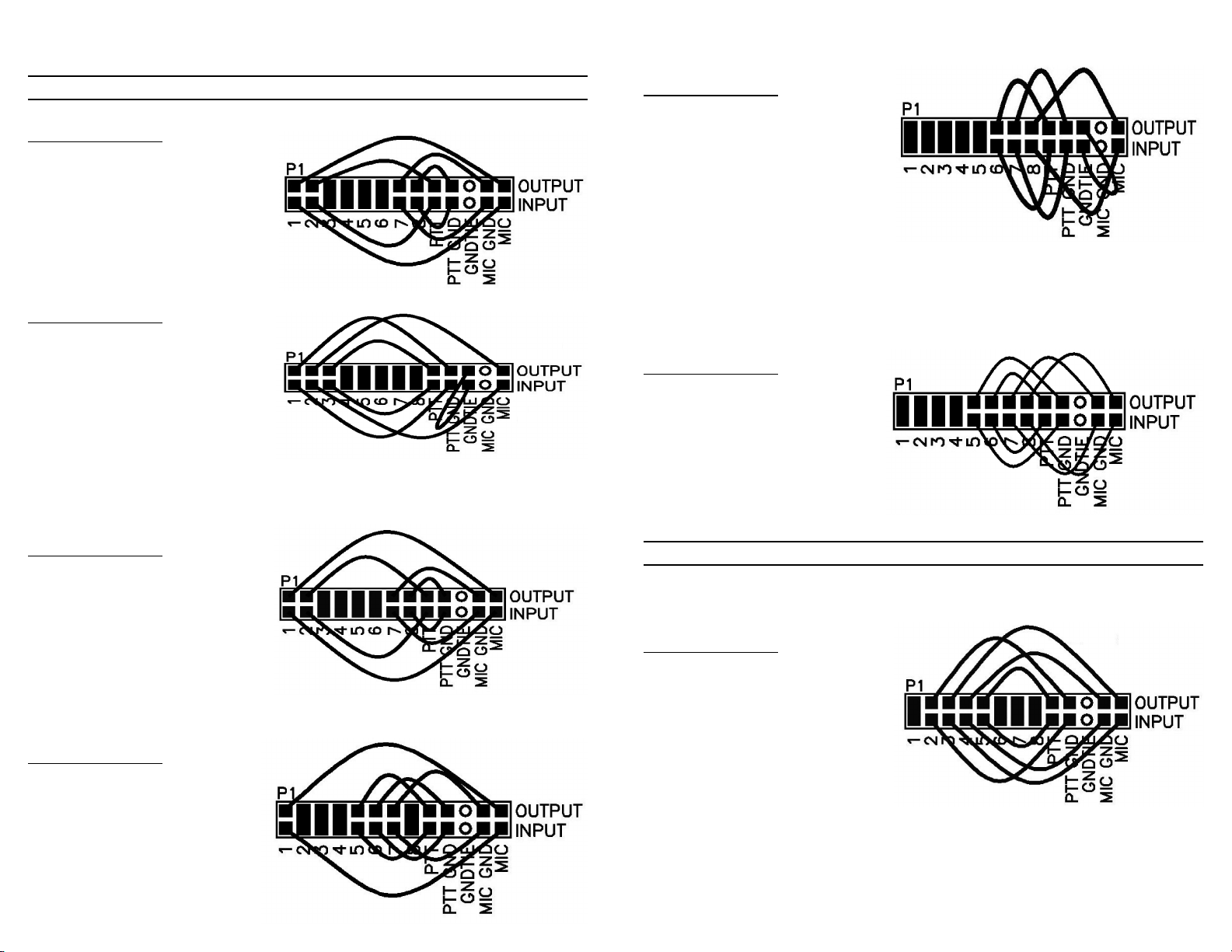
RIGblaster JUMPER INSTALLATION NOTES:
The jumper diagrams and charts in the back of this manual should be checked against
the microphone wiring diagram in your radio’s owners manual. Simply make sure that
mic. audio, mic. ground, PTT, and ptt ground are on the same pins. It is possible to
damageyourradio,butonlybyinadvertently shortingout anyDCvoltagethatmay beon
the mic. jack. Pay particular attention to this before turning on your radio.
The diagrams only depict the actual appearance of the jumper block in the RIGblaster.
Theblackrectanglesdepict wherethe bluetwo-pin jumpersgo. Theblacksquareswith
the wires depict where the black and white wire jumpers go. The circles denote no
jumpers or connections.
Remember that if your stock microphone checks out perfectly, including on the air
reports, you have the jumpers installed correctly and you are done with the jumpers.
AftercompletingthejumperInstallationyoumayputthecoveron. Carefullyaligntherear
panelover the connectorsand thecontrolmakingsurethatthesidescrewholeslineup.
Be careful not to put pressure on the switch levers with your thumbs when putting the
cover on. The screws are sheet metal type and must be driven in firmly with a fresh
properlyfitting#2phillipsheadtip.Theywillbetightatfirstandthenwillgoeasier,donot
overtighten them when they reach bottom.
PAGE 4PAGE 3

The channel selector switch allows you to choose left, right, or both channels of your
soundcard. Youwillusuallygettwiceasmuchaudiowiththeswitchinthe"both"position
because the channels are mixed together. You may use this switch to select the
appropriatechannelwhenusingsoftwarethatprocessesreceivesignalsononechannel
while transmitting on the other. The normal setting is "both".
Thevox/autoswitchselectsthemodeof PTTcontrolandtheaudioswitching. Intheauto
mode the mic. is always connected normally and the computer audio is selected
automaticallywhentheRIGblasterreceivesaPTTcontrolcommandfromthecomputer's
serialport. If thecomputeris transmittingyoumayoverrideit bypushingthePTTswitch
onyourmic.andtalking. IntheVOXmodethecomputeraudioisconnectedtoworkyour
rig'sVOXcircuit. In theRIGblastersVOX modeyoucannot use VOX,MOXor footswich
to activate your mic., only the mic. PTT button.
The "digital" LED shows green whenever the computers' audio is routed to your radio's
mic. jack. It turns green in the auto mode with serial control activation, or it is always on
whenintheVOXposition. Wheneveryoupushthemic.PTTbuttonitwillgooutindicating
that your mic is connected.
ThepowerLEDshowsthat12Vdcisapplied.TheRIGblasterhasnoon/offswitchasthe
powerconsumptionislessthan0.2wattsintheautoposition. Itwillrunforabout60years
forthepriceofapowerswitch. TheRIGblasterhasextensivepowersurgeprotectionand
it is not necessary to turn it off.
We included your choice of 3M Bumpon protective feet or double sided adhesive pads.
You may want to stick the RIGblaster down, up or sideways with the pads.
TROUBLESHOOTING
If you installed the RIGblaster following the steps in this manual you need not go back
toapreviousstep. Theproblemisisolatedtothestepthatyoufoundtheproblemon.Most
problems are software related and you need to consult your softwares' documentation.
If you would like further help, see our support page, for the latest help and
suggestions: http://www.westmountainradio.com/support.htm
Please understand that the RIGblaster will not work if the software and computer does
not work. Makesure that youhave yoursoftware operating properlybefore connecting
the RIGblaster and expecting it to work. You must read the documentation that comes
withthesoftware!Sofwareinstructions arenotincludedinthis manual. Wedidnotwrite
the software and we cannot support the software. The best thing to do if you have
softwareproblemsit totryandifferentsoftware package. Ifyouhaveproblemswithtwo
or more sound card programs you probably have a problem with you Windows sound
card software installation not your hardware.
Enjoy operating and work lots of DX!
Dan Gravereaux, N1ZZ and Del Schier, K1UHF
PAGE 6PAGE 5
control. Set all of these controls so none of them are near all of the way up or down.
Remember that all of the adjustments are all cascaded (in series), and they all interact.
Transmit. Set your RF drive to maximum while adjusting the multiple audio level
adjustments for about 50% power. You should not exceed the AM, FM or RTTY power
ratings of your radio. After setting make sure you ALC meter is below maximum.
Note that if you run your sound card at maximum and the RIGblaster level turned way
down you will have distortion from your sound card and a poor quality signal.
VOX OPERATION
To set up for vox operation, instead of automatic serial control, you need to understand
the switching within the RIGblaster. In the auto mode your mic. is connected by default
and it will work normally with your radio's VOX. In the RIGblaster's VOX mode your mic.
is disconnected and your computer audio is hooked up. Therfore, your computer audio
may activate your rig's VOX circuit.
TosettheVOXlevelcontrolsyouneedtosetallthelevelsasdescribedpreviously. Turn
yourrig'sVOXon. Setthelevel,delayandanti-tripcontrolssothatitworkswellwithyour
mic. Thesame settingsshouldworkwiththe computersince thecomputer audioshould
be matched, almost exactly, to the same level as your voice from your mic.
SWITCHES, CONNECTIONS, INDICATORS AND FEET
Thebackpanel:YouwillfindayellowDCpowerconnectorforthesuppliedACadapter.
The RIGblaster needs approximately 12 Vdc. The center pin is positive. You may run
it directly from 10 to 16 Vdc but you need tp keep the grounding physically close to the
radio's mic circuit ground. This will avoid ground currents that may spoil your transmit
audio.
The DB25 serial connector is for two way PTT control from a standard modem cable
connected to a serial port.
Theaudioleveladjustmentpotentiometer givesagreatrangeof adjusmenttomatch the
nominal output of the computer to your radio's mic. jack. Clockwise facing the back is
maximum audio level.
The audio input and outputs accept standard 1/8" stereo mini plugs. These jacks are
wiredinparalell and theoutputmay be usedtomonitor the audiofromthe computer that
is fed to the RIGblaster's input jack.
The Modular RJ45 jack accepts the supplied RIGblaster mic. cable that feeds the mic.
jack on your radio.
The Front panel: The mic. jack varies according to the RIGblaster model; the M8 has
a standard 8-pin screw on jack, the M4 has a standard 4-pin screw on jack and the
RJ has a modular RJ45 8-wire jack. This is where you connect your mic.

Basic station hookup diagram.
TRANSMIT AUDIO: Supplied 3.5 mm, 1/8”
stereo phone plug patch cord from computer’s
line* output to RIGblaster’s audio in.
PTT, KEYING & SWITCHING: Supplied DB9M
to DB9F serial cable connected between the
RIGblaster’s serial jack and computer’s com
port. (not needed for VOX)
RECEIVE AUDIO: Supplied 3.5mm, 1/8” stereo
phone plug patch cord from radio’s speaker or
line out to computer’s line* input.
MICROPHONE: Mic. cable supplied with
RIGblaster. Connection goes to front of
RIGblaster for RJ45 modular radios.
COMPUTER SPEAKER RE-CONNECT:
Cable from computer speaker re-connects
to RIGblaster’s audio output
* For laptop computers use the computer’s mic. input in place of
the line input and use the headphone output in place of the line
output.
Note: This diagram is a basic sound card station hookup and does not show a
keying connection for CW and/or FSK. That connection is user supplied and
requires an 1/8” mini jack to connect the key out of the RIGblaster to the radio’s
straight key input and/or FSK keying terminals.

RJ MODEL RIGblaster ONLY or RJ adaptor kit with M8
Icom Modular RJ45 jumper connections
IC706 (all versions) and Icom FM radios
Pin # Connection
1 Direct connection
2 PTT common (Ground)
3 Microphone audio
4 Mic. common (Ground)
5 Push to talk, PTT
6 Direct blue shunt jumper
7 Direct blue shunt jumper
8 Direct blue shunt jumper
Note: Icom manual diagram has the pin numbers inverted.
Kenwood and SGC 2020 jumper connections
Pin # Connection
1 Microphone audio
2 Push to talk, PTT
3 Direct blue shunt jumper
4 Direct blue shunt jumper
5 Direct blue shunt jumper
6 Direct blue shunt jumper
7 Mic. common (Ground)
8 PTT common (Ground)
Kachina jumper connections
Pin # Connection
1 Ground (Mic/PTT)
2 Microphone audio
3 Push to talk, PTT
4 Direct blue shunt jumper
5 Direct blue shunt jumper
6 Direct blue shunt jumper
7 Direct blue shunt jumper
8 Direct blue shunt jumper
Note: There is a wire jumper on the GNDTIE pins for common mic. and PTT ground.
PAGE 7
Typical Older Yaesu microphone jumper connections
Pin # Connection
1 Direct blue shunt jumper
2 Direct blue shunt jumper
3 Direct blue shunt jumper
4 Direct blue shunt jumper
5 Direct blue shunt jumper
6 Push to talk, PTT
7 PTT and Mic. common
8 Microphone audio
Note:If yourradio's manualshowsonly1groundpinonthemic.connectoryouhavethis
style. Notice the wire jumper on our GNDTIE pins.
Typical Newer Yaesu jumper connections
Only original mics. for FT1000MP/MK V, FT920, FT990, FT847 etc.
Pin # Connection
1 Direct blue shunt jumper
2 Direct blue shunt jumper
3 Direct blue shunt jumper
4 Direct blue shunt jumper
5 PTT common (Ground)
6 Push to talk, PTT
7 Mic. common (Ground)
8 Microphone audio
MICROPHONE JUMPER CHARTS
M8 MODEL RIGblaster ONLY
PAGE 8
Icom jumper connections
Pin # Connection
1 Microphone audio
2 Direct blue shunt jumper
3 Direct blue shunt jumper
4 Direct blue shunt jumper
5 Push to talk, PTT
6 PTT common (Ground)
7 Mic. common (Ground)
8 Direct blue shunt jumper
Typical Alinco jumper connections
Pin # Connection
1 Microphone audio
2 Push to talk, PTT
3 Direct blue shunt jumper
4 Direct blue shunt jumper
5 Direct blue shunt jumper
6 Direct blue shunt jumper
7 Mic. common (Ground)
8 PTT common (Ground)

Typical Yaesu Modular RJ45 jumper connections
FT817, FT900 AND MOST FM MOBILE RIGS
Pin # Connection
1 Direct connection
2 PTT common (Ground)
3 Push to talk, PTT
4 Microphone audio
4 MIC Ground/Common
6 Direct blue shunt jumper
7 Direct blue shunt jumper
8 Direct blue shunt jumper
M4 VERSION ONLY or M4 adaptor kit with M8
Typical Ten Tec jumper connections
Pin # Connection
1 Microphone audio
2 PTT and Mic. com/gnd
3 Push to talk, PTT
4 Direct connection
5 not used
6 not used
7 not used
8 not used
Note: There is a 2 pin jumper on the GNDTIE pin as Ten Tec uses a common mic.
and PTT ground.
Typical 4 PIN Kenwood (TS530/830) jumper connections
Pin # Connection
1 Microphone audio
2 Push to talk, PTT
3 PTT Ground/Common
4 MIC Ground/Common
5 not used
6 not used
7 not used
8 not used
PAGE 9
RIGblaster Warranty
The Compact Disc of Radio Amateur Software Collection is
excluded from any and all warranties by West Mountain Radio.
Note that the programs have been provided as shareware or
freeware by the software authors to the amateur radio commu-
nity for their use and enjoyment. The CD is to be used at your
own risk.
The RIGblaster is warranted against failure due to defects in
workmanship or materials for one year after the date of pur-
chase from West Mountain Radio. Warranty does not cover
damage caused by abuse, accident, misuse, improper or ab-
normal usage, failure to follow instructions, improper installa-
tion, alteration, lightning, or other incidence of excessive volt-
age or current. If failure occurs within this period, return the
RIGblaster or accessory to West Mountain Radio at your
shipping expense. The device or accessory will be repaired or
replaced, at our option, without charge, and returned to you at
our shipping expense. Repaired or replaced items are war-
ranted for the remainder of the original warranty period. You
will be charged for repair or replacement of the RIGblaster or
accessory made after the expiration of the warranty period.
West Mountain Radio shall have no liability or responsibility to
customer or any other person or entity with respect to any
liability, loss, or damage caused directly or indirectly by use or
performance of the products or arising out of any breach of this
warranty, including, but not limited to, any damages resulting
from inconvenience, loss of time, data, property, revenue, or
profit, or any indirect, special incidental, or consequential
damages, even if West Mountain Radio has been advised of
such damages.
Except as provided herein, West Mountain Radio makes no
express warranties and any implied warranties, including fit-
ness for a particular purpose, are limited in duration to the
stated duration provided herein.
This manual suits for next models
2
Table of contents