2833 West Chestnut Street | Washington, PA 15301 | Toll Free: 800-245-4964 | www.westpenn-wpw.com
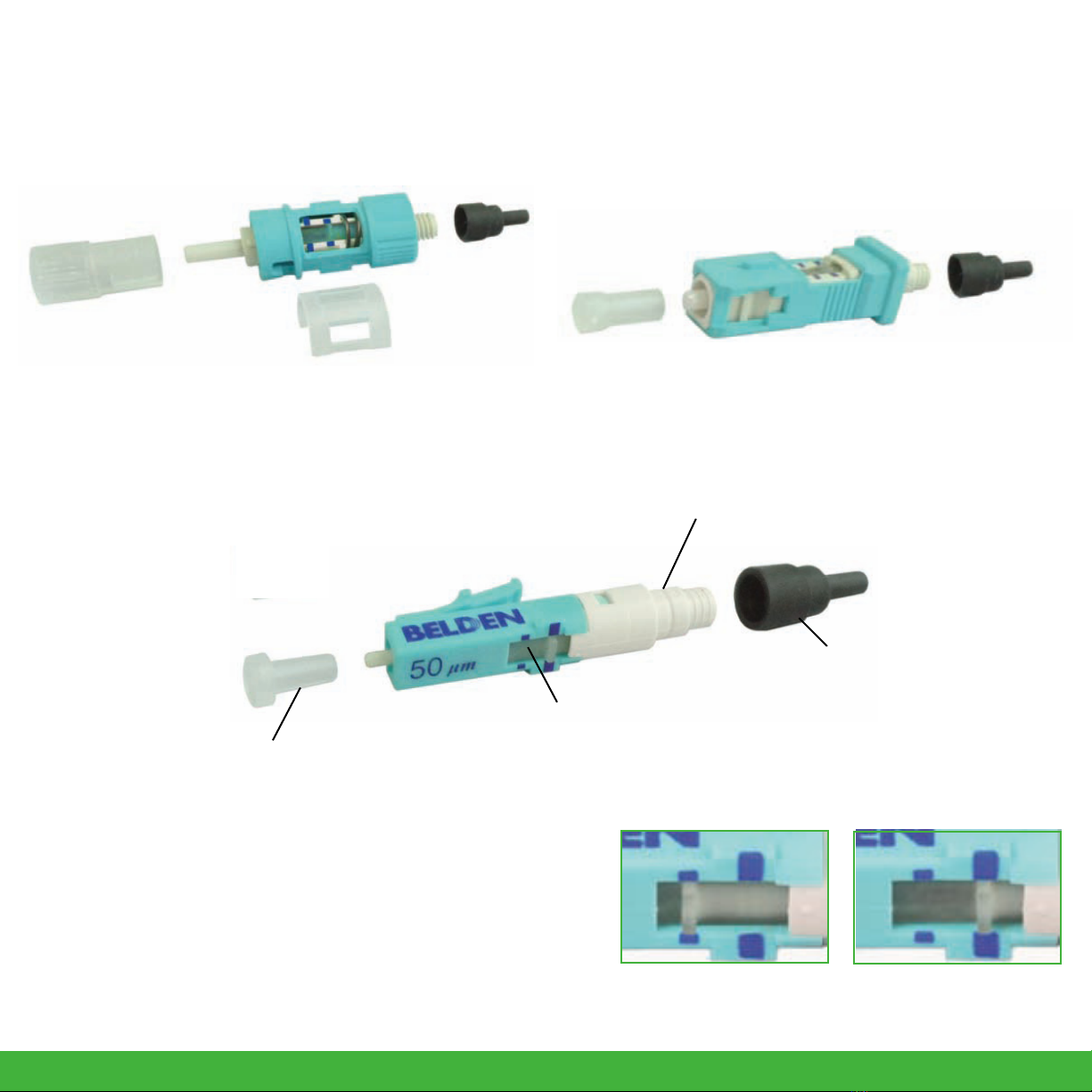
Boot
Closed Position
Section A - What’s New and What You Need to Know
is Guide Includes:
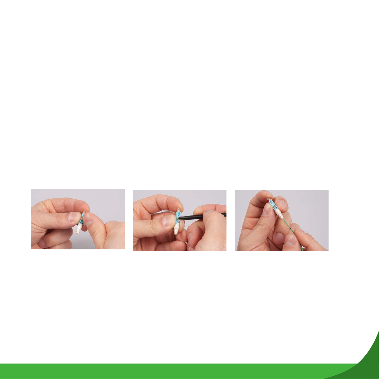
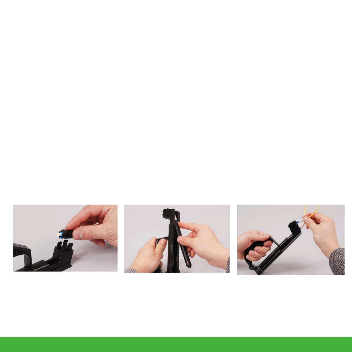
• Installation procedures for Brilliance LC, SC and ST connectors.
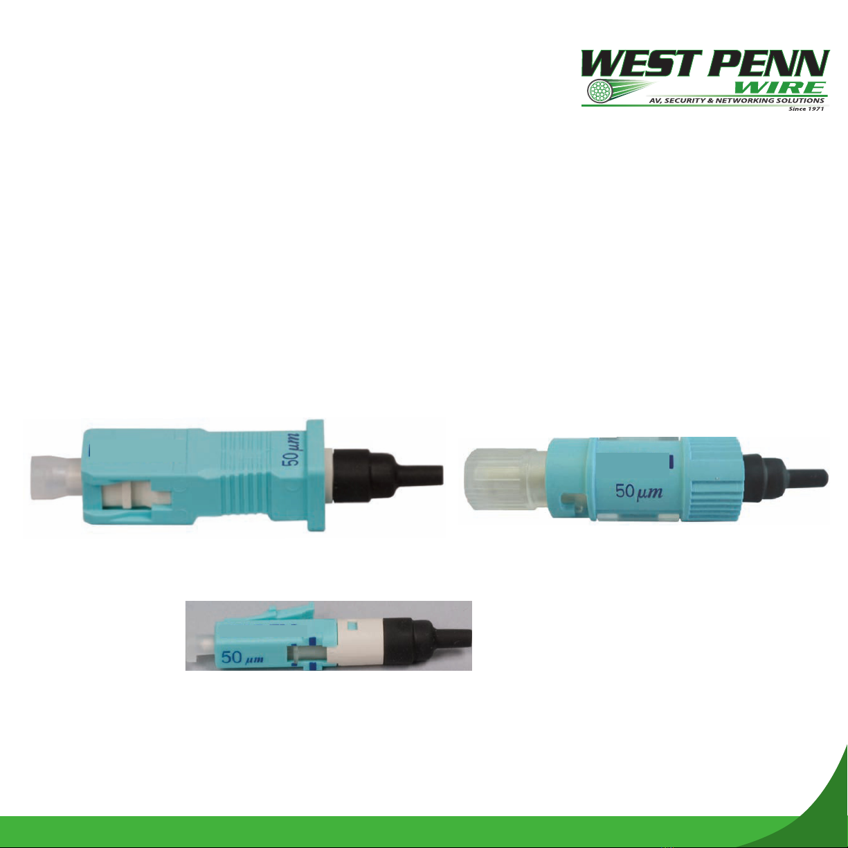
• A section describing components, features and accessories.
• Cleaning procedures.
• A troubleshooting guide and tips.
CAUTION:
• When installed on a live system, invisible laser radiation may be present.
• Do not stare into connector endface or view directly with optical instruments.
• Wear safety glasses when working with optical ber.
• Dispose of all scrap ber in the waste bottle to a void getting ber slivers.
• Do not touch cleaver blade.
Key Success Parameters
• Cleanliness:
- Keep exposed ber components clean as well as your environment.
- Keep dust caps on and avoid dust creating activities.
- Clean endface with alcohol wipes and then dry wipe as per cleaning procedures
• Cleave Quality:
- Field clea ver can produce inconsistant results, verify cleave quality with a microscope aer each cleave.
- Precision cleavers are recommended and will improve clea ve quality. However, it is important to
validate cleaver performance ever y 25 connectors or less.
• Installation Quality:
- Test connector performance at ever y 100 connector installations or less.
- Use VFL and Support Handle for best results during termination.
2833 West Chestnut Street | Washington, PA 15301 | Toll Free: 800-245-4964 | www.westpenn-wpw.com