
Section BXB‐19A‐20A 030‐101713 Rev. B R
61406IARB
‐ KNOCK‐OUT REMOVAL NOTE ‐
Always remove knock‐outs (in the Boxer cabinet mounted
above the battery box) where holes are desired before mounting
the battery box or cabinet, regardless of the type of knock‐out and
regardless of the order of the mounting steps. All knock‐outs
should be knocked out from the inside of the cabinet, except for
the small 0.575” knock‐outs (which should be knocked out from
the outside of the cabinet) or the concentric knock‐outs.
3.5.1 Removing Knock‐outs in the Top Cabinet
Regardless of the mounting type, prior to mounting and joining
the cabinets together, remove knock‐outs where access holes
will be needed in the boxer cabinet which will be installed above
the battery box.
There are five 0.575” diameter knock‐outs in the floor of the
Boxer cabinet where the battery box attaches to the cabinet
(hole patterns of both units match). Remove these small
knock‐outs (see Paragraph 3.5.1 and the KNOCK‐OUT NOTE
therein)prior to joining and mounting the cabinets. Verify all
other needed knock‐outs are removed in the cabinet where
cable access holes will be desired, including the knock‐out for
the battery cable, if not already removed.
3.5.2 Joining the Boxer Cabinet and the Battery Box
Regardless of the mounting type, attach the Boxer cabinet to
the battery box prior to mounting or installing the conjoined
units. To join the units, follow the steps below:
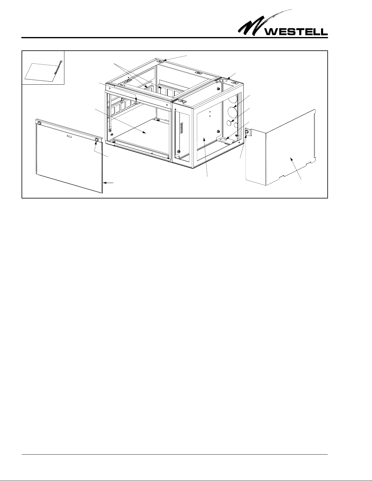
1. Open and prepare both Boxer units. Open the door of the
main Boxer cabinet and remove both access panels of the
battery box for easier handling and mounting hole access.
2. Locate and open parts/hardware kit. Find the bag of hard
ware and parts located inside the battery box. Open the
bag and spread out the parts for easy access.
3. Remove knock‐outs in the Boxer cabinet. If not already
done, remove any required knock‐outs in the cabinet (see
Paragraph 3.5.1 and the KNOCK‐OUT NOTE at this time).
4. Install stiffener bar. Install the L‐shaped stiffener bar to
the rear bottom surface of the cabinet. To do this, loosen
the AC outlet box in the lower rear right corner, orient the
bar so the mounting holes face down, slip the bar (length
wise) behind the outlet box, and place it in the back of the
cabinet where the rear wall meets the bottom surface.
Align the holes in the bar with the holes in the cabinet, and
secure the bracket to the bottom of the cabinet with the
provided hardware. Retighten the AC outlet box.
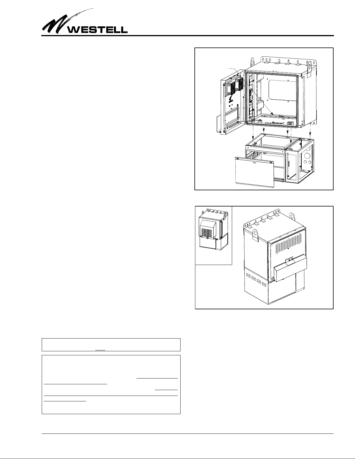
5. Set cabinet on battery box. Lift the Boxer cabinet and place
it on top of the battery box. Slide the cabinet to align the
five holes in the top surface of the battery box with the
matching holes in the bottom of the Boxer cabinet.
6. Attach cabinet to battery box. After aligning all holes, se
cure the units together by inserting, threading and
tightening a bolt (plus a washer) through each set of
aligned holes.
3.5.3 Mounting on a Concrete Pad
Follow the steps below to mount the Boxer battery box on a
concrete pad. The battery box (or an optional skirt) is required
when mounting the main Boxer cabinet on a concrete pad. Or
der and use the optional A90‐BXA19‐PT1 Pad Mount Template
Kit for mounting on a concrete pad. Use the numbered steps be
low and the instructions in Figure 7 to mount the conjoined
Boxer cabinet and battery box on a concrete pad. These instruc
tions are guidelines; you must design, dig, mix, pour, and install the
concrete pad per local building codes and practices. Note the fol
lowing additional concerns for concrete pad installations:
SVerify all required cabinet knock‐outs have been removed
(see the KNOCK‐OUT NOTE and Paragraph 3.5.1).
SSelect a mounting location that is dry, grade level or high
er, and will support a 48” X 42” wide concrete pad (min).
SIf placing the concrete pad next to an adjacent structure,
Westell suggests a 24” distance between the cable access
door panel and any structure to allow for easy cable access.
‐ CONCRETE PAD MOUNT NOTE ‐
For concrete pad mounting, prepare and pour the concrete pad
(and install the accompanying conduit or ductwork) per local
codes and company practices, insert anchors in the wet concrete
where holes at the bottom of the battery box are located (holes
are 0.344” in diameter), and allow the concrete to dry, prior to
mounting the Boxer units.
‐ CONCRETE PAD HEIGHT NOTE ‐
The pad location must be grade‐level or above ‐ it must not be be
low grade‐level. The location must be able to support the com
bined weight of both Boxer cabinets and all internal equipment.
Always follow local installation codes, procedures, and practices.
Concrete Pad Mounting Steps
1. Determine exact concrete pad location. Determine, select,
and prepare the location for the concrete pad, per compa
ny practice and local codes. When determining the size of
the pad, allow for 12” of concrete to extend out from each
side of the battery box (so the pad is a total of 2 feet wider
and 2 feet longer than the battery box).
2. Prepare template. Perform Steps 1‐3 of Figure 7.
3. Prepare the pad for conduit or ductwork. Dig and frame
the pad location per company practice. Once the pad is
framed for concrete, but before pouring gravel or con
crete, install any cable conduit or ductwork that is desired
to be routed through the concrete and which will enter the
battery box from the bottom.
4. Prepare the pad for concrete (add gravel). Fill and com
pact the pad site with gravel, per company practice.
5. Prepare and join both Boxer units. If not already done,
perform the steps in Paragraph 3.5.2 to open both Boxer
units, to locate the bag of hardware in the battery box, to
remove knock‐outs, and to join the units.
6. Pour concrete, place the template, then set insulator pad
and battery box on dry concrete. Perform Steps 4‐7 of


 user manual")


