
Section BXM‐161‐7HE‐20A
030‐101765 Rev. B
R
9
1311IARB
VProper lengths and types of communications cables
VProper lengths and types of power cables and fittings
VCable management supplies (ties, clips, markers, etc.)
VPower installation and testing equipment
VESD protection
3.5 Removing the Knock‐outs
Knock‐outs should be removed prior to mounting the cabinet.
See Figure 9 or Table 1 for knock‐out sizes, quantities, and loca
tions, and follow the steps below to remove the knock‐outs.
1. Open the cabinet door. If knock‐outs will need to be re
moved, using a 216 tool or can wrench or the provided
pin‐in‐hex wrench, open the large front door of the Box
er‐16 cabinet to access the knock‐outs.
2. Remove knock‐out(s). Prior to mounting the cabinet, per
company practice, remove as many appropriately‐sized
knock‐outs at the bottom of the cabinet as needed for the
specific application (consider ground, power, and com
munication cable access needs, venting, and whether
optionally mounting a battery box with the cabinet).
3. Install rubber grommets or conduit fittings. Install either
a heavy‐duty rubber grommet or the conduit fitting of
choice (liquid‐tight recommended) in each selected
knock‐out hole. If an optional vent is desired, the provided
vent cap can be installed in one of the smaller knock‐outs.
4. Close the cabinet door. Once the knock‐outs are removed,
lock the door using the 216 tool or can wrench, to minimize
possible product damage and personal injury.
3.6 Mounting the Cabinet
The Boxer‐16 cabinet is typically mounted outdoors, above
ground, on an H‐frame, a wall, post, a concrete pad, or a pole.
An optional mounting kit is available to support pole mounting
(from 8” to 20” in diameter). Concrete pad mounting is typically
used when used with an optional Boxer battery box or skirt. An
optional pad mount template kit is available for easy and conve
nient cement anchor placement. All mounting hardware (not
provided) must be capable of supporting the weight of the Box
er‐16 cabinet plus the weight of any equipment mounted in it.
For convenience, lift hooks or ears are provided for temporary
lifting purposes (do not use lift ears from which to hang the cabi
net in permanent installations). Run all cables to the mounting
location, perform any trenching, trench cable placements, and
backfilling prior to the cabinet mounting, and clear the installa
tion area of any debris, vegetation, and unneeded equipment or
obstacles.
‐ KNOCK‐OUT REMOVAL NOTE ‐
Always remove knock‐outs where holes are desired before
mounting cabinet or securing the battery box, regardless of the
knock‐out type and regardless of the order of the mounting steps.
All knock‐outs should be knocked out from the inside of the
cabinet, except for the small 0.575” knock‐outs (which are to be
knocked out from the outside of the cabinet) and except for the
concentric knock‐out (from either direction, per hole size).
‐ WEIGHT NOTE ‐
The Boxer‐16 cabinet weighs 80 pounds. The weight of the inter
nal equipment installed in the Boxer‐16 should not exceed 90
pounds. The mounting surface, structure, and hardware must be
able to support the combined weight (170 pounds).
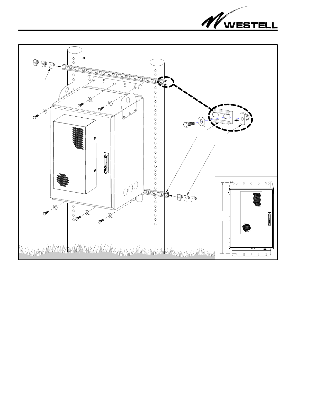
3.6.1 Mounting on an H‐Frame
To mount the Boxer‐16 on an H‐frame, the top and bottom
mounting brackets are used. Follow company practice or the
steps below to mount the Boxer‐16 cabinet on an H‐frame. See
Figure 15 for an H‐frame mounting drawing. If the installation
includes the battery box, attach the battery box to the cabinet
prior to mounting the conjoined units to the H‐Frame.
1. Determine exact mounting location in H‐frame. Select and
mark the exact horizontal and vertical final mounting loca
tion within the H‐frame. The spacing between the top and
bottom horizontal‐rail mounting holes should be 39” (on
centers). Westell recommends a height of 30” from the
ground. In addition to leaving a comfortable installer
working height, leave adequate space under Boxer‐16 for
cable access, as well as in front of the cabinet to allow the
door to open, and at the sides in the event of any multiple
installations.
2. Remove knock‐outs. See the steps in Paragraph 3.5 (Re
moving the Knock‐outs) to remove the knock‐outs where
any cable access holes (or holes for mounting the optional
battery box) are desired.
3. Prepare the H‐frame mounting hardware. Bring the ap
propriate rail nuts (to secure the cabinet to the H‐frame)
to the installation site. The mounting hardware must be
able to support the weight of the cabinet plus the weight of
the added internal equipment. Insert at least three rail
nuts into each rail (compress the spring on the nuts as
needed) and place them at the desired mounting location.
4. Lift cabinet. Lift the cabinet to the mounting height. If us
ing lift equipment, use two cables or straps of equal length,
one connected to each lift ear, for a balanced symmetrical
lift. The lift ears are provided at the top of the cabinet, one
at each side wall, and each lift ear has a 2” hole in it.
5. Attach cabinet to H‐frame rails. Align the holes in the cabi
net's top mounting bracket with the holes in the inserted
rail nuts in the H‐frame rails, then insert and install an ap
propriate bolt through each set of aligned holes. Westell
recommends a minimum of 3 mounting bolts per mount
ing flange (top and bottom). Tighten hardware appro‐
priately. Repeat for the bottom mounting bracket and H‐
frame rail. Verify the cabinet is in the proper horizontal
position, make any needed adjustments, then securely
tighten all mounting hardware.
6. Test installation firmness. Test the installation by attempt
ing to move the cabinet. Correct any looseness, if
detected. Tighten all bolts again.
7. Determine next step. If ground, power, and communica
tions cables and internal equipment will not be connected
and mounted at this time, proceed to the next step to final
ize the cabinet installation. If ground, power, and
communications cables and internal equipment will be


 user manual")


