manuals.online logo
Brands
  1. Home
  2. •
  3. Brands
  4. •
  5. Westell
  6. •
  7. Enclosure
  8. •
  9. Westell VirtualEdge VEUE-30 User manual

Westell VirtualEdge VEUE-30 User manual

Equipment Issue A
030-101705 Rev. C, August 2009
Section VEU-E30-20A
R
CopyrightE2009 Westell, Inc. All rights reserved. Westellrand VirtualEdgerare registered trademarks of Westell, Inc.
LGXris a registered trademark of Furukawa Electric North America, Inc.
Nylatchris a registered trademark of Hartwell-Dzus, Inc. Page 1 of 4
0908IARC
VirtualEdgerVEUE-30 12-Port Wall-mount Universal Enclosure
CONTENTS PAGE #
1. GENERAL 1. . . . . . . . . . . . . . . . . . . . . . . . . . . . . . . . . . . .
2. INSTALLATION 1. . . . . . . . . . . . . . . . . . . . . . . . . . . . . . .
3. CUSTOMER & TECHNICAL SERVICES 4. . . . . . . . .
4. WARRANTY & REPAIRS 4. . . . . . . . . . . . . . . . . . . . . . .
5. SPECIFICATIONS 4. . . . . . . . . . . . . . . . . . . . . . . . . . . . .
1. GENERAL
1.1 Document Purpose
This document describes Westell’s VirtualEdgerVEUE-30 se-
cure-access, 12-port, wall-mount universal enclosure designed
for flexible services hand-off to subscribers. The VEUE-30 is
shown in Figure 1.
1.2 Document Status
When this practice is updated, the reason will be stated here.
Revision B added optional splice trays. Revision C updates
Ta b l e 1 .
1.3 Product Purpose and Description
The VEUE-30 VirtualEdge Universal Enclosure (VEUE) is a
wall-mountable, compact, two-door, secure-access universal
enclosure that serves as an interface for an ethernet hand-off
point by the Telco to terminate any 10Base-T, 100Base-T,
Cat5E, fiber, or Coax services (or a combination thereof), typi-
cally at the CPE point of demarcation. The service terminated
is determined by the coupler type used inside the enclosure,
and the enclosure accommodates up to 12 field-provided cou-
plers that can be installed in one of three, detachable,
4-position, LGXr-type panels. Cable access to either the pad-
lockable Customer side of the enclosure or the key-lockable
Network side is made through either top, bottom, or side-wall
rubber grommets. Also on the Network side is a two-piece
spool for fiber cable storage (removable if space is a concern).
A removable divider wall between the compartments doubles
as a mounting plate for the three LGX-type panels.
To enable a greater variety of service and interface offerings, ser-
vice providers are putting more fiber into customer premises, via
either Fiber-to-the-Premise or placing more fiber multiplexers
and IP aggregation devices closer to subscribers. In business
markets, the strong demand for Transparent LAN and Virtual
Private Network services, where the customer’s LAN is ex-
tended over the Service Provider Network to provide native
Ethernet service, creates numerous applications for Westell’s
VirtualEdge Enclosures.
1.4 Product Mounting
The VEUE-30 is typically mounted to a wall or equipment
backboard at the customer premises hand-off point.
1.5 Product Features
The VEUE-30 offers the following features.
Figure 1. VEUE-30 Wall-mount Enclosure
SSeparate access for Network and subscriber
SSecure access demarcation
SHinged, key-locking, Network door allows full access for
Network-side technicians
SNetwork-side two-piece spool for surplus fiber cable
SInterior fiber containment lips for fiber management
SInterior, slide-out, compartment divider wall with 3 de-
tachable LGX-type panels facilitates access to and
connections for both Network and Customer sides
S12 empty coupler positions for flexible hand-off (fiber,
DS3, Ethernet)
SAccepts two splice trays (up to 24 splices)
SSmaller, hinged, padlockable and screw-locking front
door for Customer side access
SCable access via eight rubber grommets
SPredrilled, keyhole-shaped, mounting holes in rear wall
SCable tie-downs on enclosure’s back wall
SWing-nut clamp to secure fiber cable strength members
SGround lug
STransparent LAN Services
S10/100M Ethernet Services
SGigE Optical hand-off
SOptional LGX-type panels available (one with 6 SC cou-
plers, one with 6 BNC couplers)
2. INSTALLATION
Installation consists of inspecting the equipment for damages,
following proper safety precautions, gathering the required
tools and equipment, determining the mounting location,
mounting the enclosure, and making the appropriate ground-
ing, power, and wiring connections. The following paragraphs
provide detailed instructions for performing these procedures.
Section VEU-E30-20A 030-101705 Rev. C R
20908IARC
Figure 2. VEUE-30 with Customer Door Open
Customer Door
Rubber Grommet
(1 of 4 on Cust. Side)
Large Network Door
Divider Wall
Latch for
Padlock
Key Lock
Rubber Grommet
(1 of 4 on Network Side)
- INSPECTION NOTE -
Inspect the unit for damages prior to installation. If the equip-
ment was damaged in transit, report the damage to the trans-
portation company and to Westell (see Part 6).
2.1 Following Safety Precautions
- CAUTION -
Risk of electric shock. Voltages up to 140 VDC (with reference to
ground) may be present on telecommunications circuits.
- PRECAUTIONARY STATEMENT -
Never install telephone wiring during a lightning storm.
Never install telephone jacks in wet locations unless the jack
is specifically designed for wet locations.
Never touch uninsulated telephone wires or terminals unless
the telephone line has been disconnected at the network
interface.
Use caution when installing or modifying telephone lines.
This equipment is intended to be used behind devices that
provide primary lightning protection.
2.2 Gathering Tools and Supplies
The following tools and supplies are recommended to mount
the enclosure.
jAwl or drill with assorted bits
jScrewdrivers (slotted-head and/or Phillips-head)
jWood screws, or other appropriate wall fasteners
jMarking utensil
jLevel (optional)
2.2.1 Wall-Mounting the Enclosure
Mount the enclosure per local company practice, or if none ex-
ist, per the instructions below. This enclosure is typically
wall-mounted at the customer premises. Westell recommends
mounting the enclosure to a backboard, concrete surface, or
other noncombustible surface. The enclosure has a rear wall
with five keyhole-shaped mounting holes, for easier mounting.
1. Open the larger Network door with the provided key, lift and
place the enclosure against the wall in the desired mounting
location (level it if desired), then with a marking utensil, mark
Lift VEUE30 and use its rear wall as a template to mark the mounting hole locations.
Use mounting screws with head diameter less than the mounting’s keyhole slot diameter.
Figure 3. Wall-Mounting the VEUE-30
Wall or backboard
Noncombustible
Network Door
Open
Keyhole mounting slots (4)
Wood Screws
(not provided) Compartment
wall divider
the mounting hole locations. For easier access to all keyhole-
shaped mounting holes, also unscrew then pull out the
removable, interior, compartment wall divider.
- MOUNTING NOTE -
Leave enough space on both sides of the enclosure (approxi-
mately 3 inches) to allow the doors to open.
2. After marking the mounting screw-hole locations, set aside
the enclosure. Drill appropriately-sized pilot holes (to ac-
commodate the mounting screws being used) at the marked
locations before the next step. Hardware for mounting the en-
closure to the wall is not included. Do not make the holes too
large, to help insure a snug fit.
3. Partially install all screws, leaving approximately ¼-inch pro-
truding for hanging the mounting from the keyhole-shaped
holes provided in the rear wall.
4. Lift the enclosure again, align the mounting holes on the en-
closure rear wall with the partially-installed screws, and hang
the enclosure on the protruding screws.
5. Tighten all screws in place. Close and lock the door if installer
connections will not be made at this time.
- GROUNDING NOTE -
Always follow local safety precautions and standard operating proce-
dures for grounding the equipment when installing, upgrading, repairing
or maintaining equipment. Any instructions or information contained
herein is subordinate to local codes, operating procedures or practices.
2.3 Making Ground Connections
The enclosure is shipped from the factory with a ground lug (in
a bag of parts) capable of accepting #6 ground wire for wall-
mount applications. The installer should locate the ground lug
and hex-nut from the bag of parts shipped with the panel and
install the lug (using the provided screw) on the post located on
the left outside wall of the enclosure (see Figure 4), securing
the ground lug via the threaded hole in the enclosure. The in-
staller then makes the ground connection to the ground lug
using a #6 ground wire and then grounds the enclosure to an
earth ground or according to local installation procedures for
grounding and bonding equipment.
2.4 Installer Connections
After mounting the enclosure, installer connections may be
performed. Figure 4 and Figure 5 show the interior removable
compartment divider wall where the couplers will be installed.
Section VEU-E30-20A
030-101705 Rev. C
R
3
0908IARC
Figure 4. VEUE-30 with Network Door Open
Network Door
Left, Network Side Right, Customer Side
Flange to protect
Rubber
Grommet
Cable
One half of
Compartment
Divider Wall
Fiber Spool
LGX-type panels
Tie-down
Fiber
Containment
Lip
Wing-nut clamp for
cable strength members
Rubber-backed
(2 each wall)
Ground lug
on outside wall
LGXr-type
panel
Figure 5. Detaching the Divider Wall and Panels
Door
removed
in this
view
Divider wall screw
Divider wall
Divider wall guide
Cable
tie-down
Lip
Mounting bracket, equipped with optional splice tray (see Inset A)
INSET A
2 splice trays can
be mounted on the
posts of the optiomal
splice tray mounting
bracket. Mount the
A90-VECMSPTY01
A90-VECMSPTY00
A90-VECMSPTY01
tray first.
A90-VECMSPTY01’s mounting bracket
Nylatchrfastener
LGXr-type panel with
empty Keystone-type ports
2.4.1 Making Network Connections
The Facility or Network side wiring and termination connec-
tions are made in the left-side compartment of the enclosure.
1. Open the large Network-side door (Figure 4) with the key.
2. For easy hand access, optionally remove the interior compart-
ment divider wall (see Figure 5) by loosening the two
Phillips-head screws at the front of the divider and sliding or
pulling out the divider wall.
3. Install the couplers of choice (up to 12) into the empty Key-
stone coupler holes provided in the three LGXr-type panels
mounted on the wall divider. If desired, the panels also can be
detached by removing (pull out on plungers) the Nylatchrfas-
teners. Couplers used vary per the application and company
practice. To re-attach the panel, simply press the Nylatch fas-
teners into their corresponding mounting holes, then press on
the plungers.
4. If removed, re-install the compartment divider wall, which is
now equipped with the couplers of choice. Tighten the screws
that hold the divider wall in place.
5. Select which of the four cable access hole(s) on the Network
side will be used for Network cable entrance. The cable may
enter the enclosure through any of the rubber grommets pro-
vided in the cable access holes. At the selected grommeted
cable access hole, carefully cut one or two slits through the
rubber grommet with a sharp object or knife, placing the
slit(s) within the +" shaped indentation in the grommet.
Make the slit just large enough to allow the fiber, wire, or
cable of choice to fit through the grommet.
6. Route all Network fiber, wires, or cables through the grom-
met. Make the grommet slit larger if needed.
7. Prepare the cable per any company practice and cable type.
8. Per company practice, after pulling the proper length of cable
inside the enclosure, use the cable tie-downs located on the
back wall near each cable access hole and the rubber-backed
washer and wing-nut to secure the cable(s) at the point of en-
closure entrance. Per company practice and cable type,
expose the cable’s strength members or Kevlar, slip them un-
der the tie-downs and then under the loosened wing-nut and
rubber-backed washer, then firmly tighten the wing-nut
(wing-nut serves as a cable strength member clamp). Any Ke-
vlar also may be wrapped around the tie-downs and stud.
9. Perform any required splicing, per company practice. Up to 2
optional fiber splice trays (for up to 24 splices) can be mounted
inside the VEUE-30 (see Table 2 for ordering information). To
mount the trays: 1) Remove the 2-piece fiber spool, 2) install the
bracket equipped with the A90-VECMSPTY01 splice tray to the
posts [Figure 5] on the enclosure’s rear wall, 3) re-install the
2-piece spool, and 4) mount the trays to the bracket after splicing
is performed by aligning the holes in the tray(s) with the mount-
ing posts provided for them on the bracket.
10. Manage any cable slack or lengths of surplus cable by wrap-
ping or looping it around the provided cable management
spool (take-up reel). Tuck any loose loops of cable or fiber be-
hind the wide cable containment lips located at the top and
bottom walls of the enclosure.
Section VEU-E30-20A 030-101705 Rev. C R
40908IARC
11. Insert all Network cables (or pigtails) into their proper cou-
plers on the Network side of the compartment divider wall.
12. If no Customer connections are to be made at this time, secure
the divider wall by tightening the two locking screws.
13. After all connections are made, secure/lock the large exterior
Network door.
2.4.2 Making Customer Interface Connections
The Customer wiring and termination connections are made in
the right-side compartment of the enclosure.
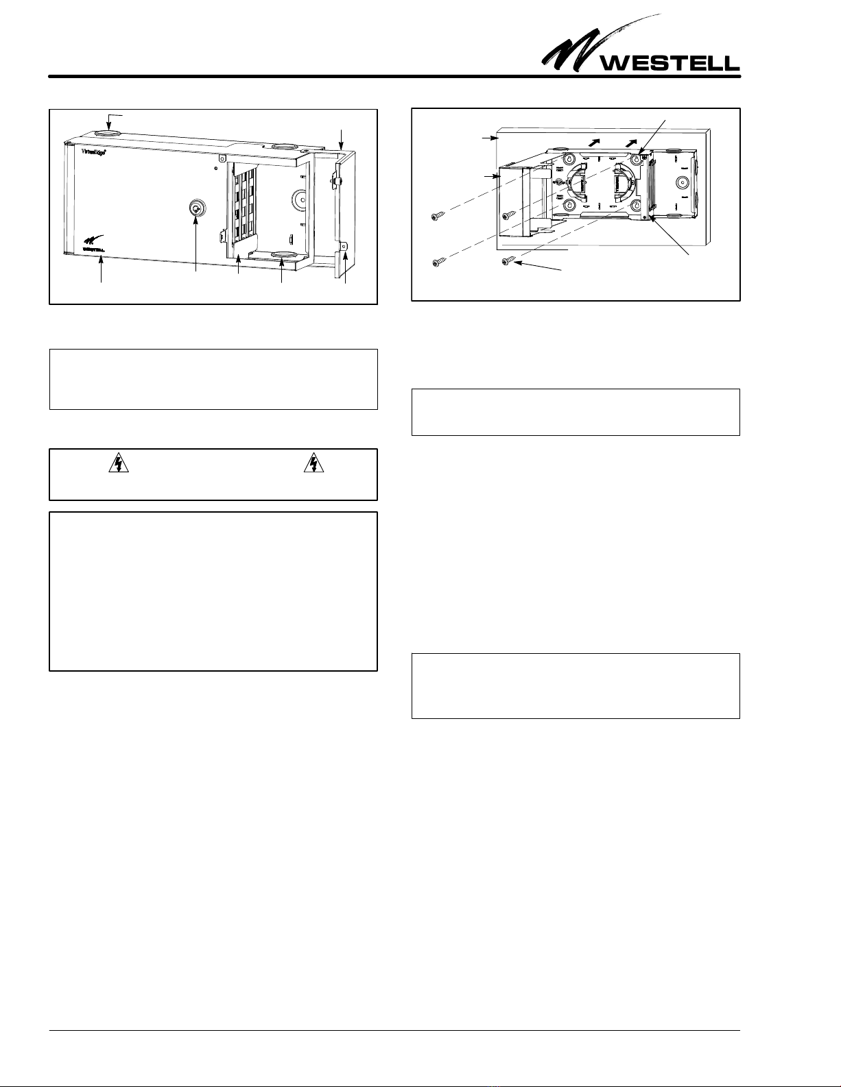
1. Open the Customer-side door (see Figure 2) by unscrewing
the two screws and removing any optional padlock.
2. Using any of cable access holes, with a sharp object or knife
carefully cut one or two slits through the rubber grommet pro-
vided in the cable access hole. Make the slit just large enough
to allow the wires and cables to fit through the grommet.
3. Route all Customer wires or cables through the grommet.
4. Attach or secure each Customer’s cable plug or connector to
the appropriate customer-side coupler on the LGX-type pan-
el mounted on the compartment divider wall.
5. Per company practice, use the tie-downs located on the wall
near each cable access hole to secure the cable(s) as it enters
the enclosure.
6. After all Customer connections are made, secure and lock all
doors.
3. CUSTOMER & TECHNICAL SERVICES
3.1 Customer Assistance. For technical or customer assistance
is required, contact Westell by calling or using one of the follow-
ing options:
Voice: (800) 377-8766
email: [email protected]
For additional information about Westell, visit the Westell
World Wide Website at http://www.Westell.com.
3.2 Part Numbers. This equipment is identified by a part num-
ber (A90-VEUE30), which consists of an issue letter of the
equipment (A), the assembly type (90), and the specific model
number (VEUE30). When a change is made to the product
which changes the form, fit, or function of the product, the issue
letter is incremented by one. Please indicate the issue level and
model number when making inquiries about the equipment.
3.3 Part Numbers
4. WARRANTY & REPAIRS
4.1 Warranty. Westell warrants this product to be defect free
at shipment time, and warrants the product to be fully func-
tional for the time period specified by the terms and conditions
governing the product sale. Equipment repairs/modifications
by unauthorized persons will void the warranty.
4.2 Repair and Return. Westell will repair or replace this unit
without cost during the warranty period if the unit is defective
for any reason other than abuse, improper use, or improper
installation. To return defective equipment, first request a Re-
turn Material Authorization (RMA) number from Westell by
calling or using one of the options shown below. Once an RMA
number is obtained, return the defective unit (freight prepaid),
along with a brief problem description, to the address we will
provide to you when you contact us.
Voice: (630) 375-4457
email: [email protected]
Replacements will be shipped in the fastest manner consistent
with the urgency of the situation. Westell will continue to repair
or replace faulty equipment beyond the warranty period for a
nominal charge. Contact Westell for details.
5. SPECIFICATIONS
To order units, call the telephone number shown in Paragraph
3.1 and please specify the part number shown in Table 2. The
physical specifications are shown in Table 1.
Physical Feature U.S. Metric
Height 7.25 inches 18.4 cm
Width (closed) 18 inches 45.7 cm
Depth (including locks) 5.5 inches 14 cm
Weight (approx.) 7.5 pounds 3.4 Kilograms
Operating Temp. -40°to +167°F-40°to +75°C
Humidity 5 to 95% (non-condensing)
Table 1. Physical Specifications
Part # Description
A90-VEUE30 VirtualEdger12-port wall-mount universal enclosure
with interior 2-piece fiber spool, 3 LGXr-type panels (4
ports each), full-size Network door and smaller
customer door.
A90-VECE30 VirtualEdger12-port wall-mount universal enclosure
with interior 12-splice fiber tray, 2-piece fiber spool, 3
LGX-type panels (4 ports each), 4 SC couplers, fiber
pigtail, fiber cable compression fitting, and full-size
door.
Other Panels, and Panel Accessories and Options*
A90-VE118BNC6 LGX-type panel with 6 BNC couplers
A90-VE118SCU6 LGX-type panel with 6 SC/UPC couplers
A90-VE118SCA6 LGX-type panel with 6 SC/APC couplers
A90-VE118SCA8 LGX-type panel with 8 SC/APC couplers
A90-VECMSPTY00 Fiber splice tray with holders for 12 splices
A90-VECMSPTY01 Same as above tray (12 splices)
but with a mounting bracket.
023-700200 Fiber cable, 4 SC male connector to stub (2 meters)
A90-VECPL5E10 CAT 5e RJ48 Keystone
style coupler (Qty = 10)
A90-VECPLBNC10 BNC COAX coupler
(Qty = 10)
A90-VECPLSC1 Fiber coupler with SC
connectors (Qty = 1)
A90-VECPLLC1 Fiber coupler with LC
connectors (Qty = 1)
A90-VECPL5EIDC10 CAT 5e coupler with IDC termination on Network side
(Qty = 10)
*A variety of cables and fiber jumpers also are available. Call Westell for details.
Table 2. Ordering and Option Information

Other Westell Enclosure manuals

Westell DSAWM-214ALCI2 User manual

Westell

Westell DSAWM-214ALCI2 User manual

Westell OmniPak 8 User manual

Westell

Westell OmniPak 8 User manual

Westell DTWA528-04 Series User manual

Westell

Westell DTWA528-04 Series User manual

Westell Boxer BXM1619-7HE User manual

Westell

Westell Boxer BXM1619-7HE User manual

Westell A90-DCP10X10 User manual

Westell

Westell A90-DCP10X10 User manual

Westell Boxer BXB19-A User manual

Westell

Westell Boxer BXB19-A User manual

Popular Enclosure manuals by other brands

HP BladeSystem c-Class troubleshooting guide

HP

HP BladeSystem c-Class troubleshooting guide

Salsbury Industries 51000 Series installation instructions

Salsbury Industries

Salsbury Industries 51000 Series installation instructions

Icy Dock MB672SKGF user manual

Icy Dock

Icy Dock MB672SKGF user manual

Winter ONE V12 user guide

Winter

Winter ONE V12 user guide

PEERLESS Mounts FPECMI-01 Installation and assembly

PEERLESS Mounts

PEERLESS Mounts FPECMI-01 Installation and assembly

Pulsar AWO513 Assembly instruction

Pulsar

Pulsar AWO513 Assembly instruction

Sharkoon REBEL C50 RGB manual

Sharkoon

Sharkoon REBEL C50 RGB manual

COUGAR CONQUER manual

COUGAR

COUGAR CONQUER manual

ZALMAN MS800 manual

ZALMAN

ZALMAN MS800 manual

Noble Niche 301 installation instructions

Noble

Noble Niche 301 installation instructions

Icy Box IB-3740-C31 manual

Icy Box

Icy Box IB-3740-C31 manual

Lakes Bathrooms Coastline Series Installation & maintenance instructions

Lakes Bathrooms

Lakes Bathrooms Coastline Series Installation & maintenance instructions

ADTRAN T200 FNID Installation and Maintenance

ADTRAN

ADTRAN T200 FNID Installation and Maintenance

Akitio Thunder3 Duo Pro Setup guide

Akitio

Akitio Thunder3 Duo Pro Setup guide

Code Blue CB 4 Series Administrator's guide

Code Blue

Code Blue CB 4 Series Administrator's guide

Antec Solution SLK1650 User's user manual

Antec

Antec Solution SLK1650 User's user manual

StarTech.com S352BU33HR user guide

StarTech.com

StarTech.com S352BU33HR user guide

Electro-Voice Marquis KD9 Instruction booklet

Electro-Voice

Electro-Voice Marquis KD9 Instruction booklet

manuals.online logo
manuals.online logoBrands
  • About & Mission
  • Contact us
  • Privacy Policy
  • Terms and Conditions

Copyright 2025 Manuals.Online. All Rights Reserved.