manuals.online logo
Brands
  1. Home
  2. •
  3. Brands
  4. •
  5. Westell
  6. •
  7. Recording Equipment
  8. •
  9. Westell RJ48C-28I2 User manual

Westell RJ48C-28I2 User manual

Equipment Issue 2
030‐101676 Rev. C, December 2010
Section RJ4‐8C0‐202
R
1012I2RC
ECopyright 2010 Westell, Inc. All rights reserved.
200 MECHANICSRis a registered trademark of Westell, Inc. Page 1 of 4
RJ48C‐28I2 and RJ48C‐28BAI2 Jack Interface Panels
CONTENTS PAGE #
1. GENERAL 1....................................
2. INSTALLATION 1...............................
3. TESTING 2.....................................
4. CUSTOMER & TECHNICAL SERVICES 2.........
5. WARRANTY & REPAIRS 4.......................
6. SPECIFICATIONS 4.............................
1. GENERAL
1.1 Document Purpose
This document describes the Westell RJ48C (Issue 2) Series of
Jack Interface Panels. An RJ48C jack panel is shown in
Figure 1. See Table 3 for specific model numbers and descrip
tions.
1.2 Document Status
Revision C of this practice updates Paragraphs 1.3, 2.2.1,
Figure 3, deletes the previous Figure 4, Table 2, and Table 5,
and adds the current Table 2 and Figure 4 through Figure 6.
Revision B of this practice updated all text and drawings which
describe or show the mounting ears (additional holes added).
Revision A replaced 030‐101336 for the models shown in
Table 3 and updated the company contact information. Prac
tice 030‐101336 replaced practice 057‐017701. Whenever this
practice is updated, the reason will be stated in this paragraph.
1.3 Product Purpose and Description
The RJ48C‐28I2 and RJ48C‐28BAI2 28‐position T1 jack pan
els provide easy Customer Interface (CI) connections for
operation in 1.544Mbps High‐capacity Digital Services (Hi‐Cap)
applications. Provided at the front of the jack panel are 28
RJ48C jacks for customer connections. At the rear are two,
64‐pin, male, Amphenol connectors for Customer or Network
connections. Two, 64‐pin, female, Amphenol‐type cables are
needed (provided with the RJ48C‐28I2 model only) to inter
face the panel with the nearby shelf assembly. See Table 3 for
ordering information for the panels and various cables.
1.4 Mounting Location
The jack panel may be mounted in a 19” or 23” relay rack or on
a wall. The panel occupies 2 Rack Units (RUs) or 3.5” of verti
cal space and is mounted above or below a 31MA228 or
DSA‐2280I3 shelf assembly. It also may be mounted facing the
circuit‐card side or the wire‐side of the shelf assembly.
1.5 Product Features
The jack panel offers the following features.
SMounts in a 19” or 23” relay rack (2 RUs) or on a wall
SDetachable and reversible mounting ears allow wall or rack
mounting, and either flush or projected rack orientations
STwo, 64‐pin, male connectors at the rear of the panel allow
Customer Interface (CI) or Network Interface (NI) con
nections to the nearby shelf assembly
Figure 1. Isometric View of RJ48C Jack Panel Interface
Ears shown mounted in most projected position.
S28 RJ48C jacks at front panel
STwo, 64‐pin, female, 3' amphenol cables (RJ48C‐28I2 only)
SHoles, tie‐downs, and cable ties for cable management
SGround lug (inside of side wall)
SUL 1863 compliant
2. INSTALLATION
Installation consists of inspecting the equipment for damages,
following proper safety precautions, attaching the mounting
ears in the correct position for the desired mounting type,
mounting the jack panel in a rack or on a wall, and connecting
cables per company practice.
‐ INSPECTION NOTE ‐
Visually inspect the unit for damage prior to installation. If the
equipment was damaged in transit, immediately report the damage
to the transportation company and to Westell (see Part 6).
‐ PRECAUTIONARY STATEMENT ‐
Never install telephone wiring during a lightning storm.
Never install telephone jacks in wet locations unless the jack is
specifically designed for wet locations.
Never touch uninsulated telephone wires or terminals unless the
telephone line has been disconnected at the network interface.
Use caution when installing or modifying telephone lines.
2.1 Jack Panel Installation
There are two mounting types; one is rack mounting and the
other is wall mounting. See Table 1 for a step‐by‐step installa
tion procedure and refer to Figure 3 if needed.
2.1.1 Rack Mounting
The jack panel can be mounted in both 19” and 23” relay racks.
The panel ships with the ears attached in the 23” rack mount
position. The mounting ears may be detached from the panel,
reversed, and re‐attached for 19” rack mounting.
2.1.2 Wall Mounting
The jack panel may be mounted on a wall. It is recommended
that local company practices be followed for wall mounting and
that ½‐inch or ¾‐inch plywood be mounted to the wall prior to
installing the panel. For best cable access and hand mobility, at
tach the 64‐pin cables and secure cable ties prior to mounting
Section RJ4‐8C0‐202 030‐101676 Rev. C R
21012I2RC
to the wall. The mounting ears may be detached (panel is
shipped with ears in the 23” rack mount position, as shown in
Figure 3), re‐positioned, and re‐attached for wall mounting ap
plications.
Step Mounting Task/Description
1. Unpack/inspect. Unpack the unit and determine if it has been
damaged. See return instructions in Paragraph 5.2.
2. Get tools. Gather all mounting hardware and tools.
3. Determine mounting type and ear position. The panel is shipped
with the ears attached for projected mounting in a 23” relay rack (see
Figure 3). If flush mounting in a 23” rack is desired, or if either 19”
rack or wall mounting is desired, remove, re‐adjust, and re‐attach
the ears in the desired position, as explained below.
4. Attach ears per correct mounting type. First detach the ears by
removing the two screws that secure each ear.
For projected 23” rack mounting, do not remove the ears.
For a flush 23” rack mounting, move the ears further forward on the
side of the panel. Align the holes in the ear's short flange with the
front‐most set of holes on the side of the panel, insert and thread the
screws through the aligned holes, then tighten the screws.
For 19” rack mounting, flip the removed ears so that the long flange
of the L‐shaped ear is against or abuts the side of the panel. If flush
mounting within the rack is desired, align the front‐most holes in the
ear's long flange with the front‐most set of holes in the side of the
panel. If a projected mounting position in the rack is desired, align
the holes in the ear's long flange with the rear‐most set of holes in
the side of the panel. When the holes are aligned, insert and thread
the screws through the aligned holes. Tighten the screws.
For wall mounting, any ear position (or hole set) may be selected,
per company practice and application and for the best cable access.
Align the selected ear holes with the selected holes in the side of the
panel, then thread and tighten the screws.
5. Ground panel. Use ground lug on inside wall to ground the panel.
6. For wall mounting only, attach 64‐pin cables then mount to wall.
Remove the 64‐pin connector covers at the back of the panel. Install
the 64‐pin cables at the back of the panel. Route cables through the
large cable access hole in the side of the panel, if needed. Secure
cables with cable ties. Last, mount panel to wall per local practice.
7. For rack‐mounting, mount to rack then attach 64‐pin cables.
Mount the panel to the desired 2RU rack position. Remove the 64‐pin
connector covers at the back of the panel. Install the 64‐pin cables at
the back of the panel. Route cables through the large cable access
hole in the side of the panel if needed. Secure cables with cable ties.
8. Install RJ48C cables. Install all required RJ48C cables at the front
of the panel, per company practice, and label all connections.
Table 1. Step‐by‐Step Installation
2.2 Installer Connections
2.2.1 Signal Connections
Connections are made at the front of the panel to the RJ48C
jacks, and at the rear of the panel at 64‐pin connectors. See
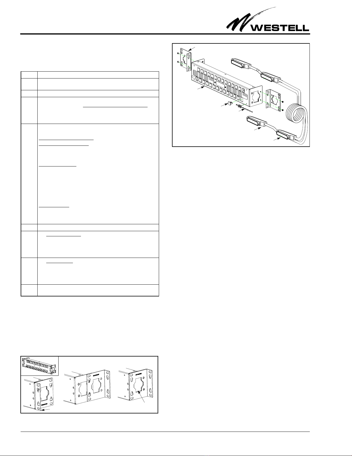
Figure 2. 19” Rack‐Mount Ear Positions on Panel
Ear in flush, 19”,
rack‐mount position.
Ear in most‐projected, 19”,
rack/wall mount position.
Ear in shallow‐projected, 19”,
rack/wall mount position.
Hole for rear
cable access
Figure 3. Exploded View of RJ48C Jack Interface Panel
*Ears shown here in shipped position (projected, 23” rack‐mounting)
(reverse or flip ears for 19” rack mounting, as shown in Figure 2)
RJ48C
Jack Interface
Panel
Jack
Cover*
Cable
tie*
RCV
XMT
Two, 64‐pin, 3',
female‐ended cables
are provided with the
RJ48C‐28I2 model
*Mounting ears, cable ties, tie‐holders,
jacks, and jack covers provided*
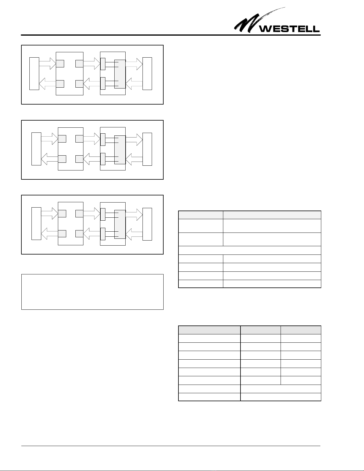
Table 2 for the jack panel's jack and connector pin‐outs. The
RJ48C Jacks on the front of the Jack panel provide the customer
interface. The 64 pin connectors on the rear of the panel provide
the interface to the network. The 64 pin connector labeled XMT
is signal from the network to the customer equipment (AZ).
The 64 pin connector labeled RCV is signal from the customer
equipment to the network (ZA).
2.2.2 Power and Ground Connections
No power connections are required. A chassis ground is pro
vided via metal to metal contact.
3. TESTING & TROUBLESHOOTING
3.1 Testing
Initial testing consists of performing the procedures indicated
for the plug‐ins installed in the shelf assembly. If trouble is en
countered, verify all installer connections to the assembly, that
no fuse is blown, and that modules are properly inserted.
This equipment should not be field repaired. If the equipment
is suspected of being faulty, replace it with another unit and re
test. If the replacement appears to operate correctly, the
original may be faulty and may be returned to Westell for repair
or replacement (see Paragraph 5.2).
3.2 Troubleshooting
If trouble is encountered, verify all connections to the panel
and to the assembly. If trouble persists, replace the suspect unit
and repeat procedures outlined. These procedures are not de
signed to effect repairs or modifications. Any tests beyond
those outlined herein, or repairs made beyond replacing a
faulty unit, are not recommended and may void the warranty.
4. CUSTOMER & TECHNICAL SERVICES
If technical or customer assistance is required, contact Westell
by calling or using one of the following options:
Voice: (800) 377‐8766
email: [email protected]
For additional information about Westell, visit the Westell
World Wide Website at http://www.westell.com.
Section RJ4‐8C0‐202
030‐101676 Rev. C
R
3
1012I2RC
RJ48C
Jack
RJ48C
Pin #
64‐Pin Connectors RJ48C
Jack & Pin #
RJ48C
Pin #
64‐Pin Connector
RCV XMT RCV XMT
J1
Pin 5 T Pin 33
J15
Pin 5 T Pin 47
Pin 4 R Pin 1 Pin 4 R Pin 15
Pin 1 R1 Pin 33 Pin 1 R1 Pin 47
Pin 2 T1 Pin 1 Pin 2 T1 Pin 15
J2
Pin 5 T Pin 34
J16
Pin 5 T Pin 48
Pin 4 R Pin 2 Pin 4 R Pin 16
Pin 1 R1 Pin 34 Pin 1 R1 Pin 48
Pin 2 T1 Pin 2 Pin 2 T1 Pin 16
J3
Pin 5 T Pin 35
J17
Pin 5 T Pin 49
Pin 4 R Pin 3 Pin 4 R Pin 17
Pin 1 R1 Pin 35 Pin 1 R1 Pin 49
Pin 2 T1 Pin 3 Pin 2 T1 Pin 17
J4
Pin 5 T Pin 36
J18
Pin 5 T Pin 50
Pin 4 R Pin 4 Pin 4 R Pin 18
Pin 1 R1 Pin 36 Pin 1 R1 Pin 50
Pin 2 T1 Pin 4 Pin 2 T1 Pin 18
J5
Pin 5 T Pin 37
J19
Pin 5 T Pin 51
Pin 4 R Pin 5 Pin 4 R Pin 19
Pin 1 R1 Pin 37 Pin 1 R1 Pin 51
Pin 2 T1 Pin 5 Pin 2 T1 Pin 19
J6
Pin 5 T Pin 38
J20
Pin 5 T Pin 52
Pin 4 R Pin 6 Pin 4 R Pin 20
Pin 1 R1 Pin 38 Pin 1 R1 Pin 52
Pin 2 T1 Pin 6 Pin 2 T1 Pin 20
J7
Pin 5 T Pin 39
J21
Pin 5 T Pin 53
Pin 4 R Pin 7 Pin 4 R Pin 21
Pin 1 R1 Pin 39 Pin 1 R1 Pin 53
Pin 2 T1 Pin 7 Pin 2 T1 Pin 21
J8
Pin 5 T Pin 40
J22
Pin 5 T Pin 54
Pin 4 R Pin 8 Pin 4 R Pin 22
Pin 1 R1 Pin 40 Pin 1 R1 Pin 54
Pin 2 T1 Pin 8 Pin 2 T1 Pin 22
J9
Pin 5 T Pin 41
J23
Pin 5 T Pin 55
Pin 4 R Pin 9 Pin 4 R Pin 23
Pin 1 R1 Pin 41 Pin 1 R1 Pin 55
Pin 2 T1 Pin 9 Pin 2 T1 Pin 23
J10
Pin 5 T Pin 42
J24
Pin 5 T Pin 56
Pin 4 R Pin 10 Pin 4 R Pin 24
Pin 1 R1 Pin 42 Pin 1 R1 Pin 56
Pin 2 T1 Pin 10 Pin 2 T1 Pin 24
J11
Pin 5 T Pin 43
J25
Pin 5 T Pin 57
Pin 4 R Pin 11 Pin 4 R Pin 25
Pin 1 R1 Pin 43 Pin 1 R1 Pin 57
Pin 2 T1 Pin 11 Pin 2 T1 Pin 25
J12
Pin 5 T Pin 44
J26
Pin 5 T Pin 58
Pin 4 R Pin 12 Pin 4 R Pin 26
Pin 1 R1 Pin 44 Pin 1 R1 Pin 58
Pin 2 T1 Pin 12 Pin 2 T1 Pin 26
J13
Pin 5 T Pin 45
J27
Pin 5 T Pin 59
Pin 4 R Pin 13 Pin 4 R Pin 27
Pin 1 R1 Pin 45 Pin 1 R1 Pin 59
Pin 2 T1 Pin 13 Pin 2 T1 Pin 27
J14
Pin 5 T Pin 46
J28
Pin 5 T Pin 60
Pin 4 R Pin 14 Pin 4 R Pin 28
Pin 1 R1 Pin 46 Pin 1 R1 Pin 60
Pin 2 T1 Pin 14 Pin 2 T1 Pin 28
Table 2. Jack Panel Connector and Jack Pin‐outs
Section RJ4‐8C0‐202 030‐101676 Rev. C R
41012I2RC
RJ48C
RJ48C
A−Z
Z−AZ−AZ−A
A−ZA−Z
Figure 4. Application 1: Using Panel with a DTMA528
Network
CPE
P1
P2
P4
P3
XMT*
RCV**
DTMA528-28I4 RJ48C-28I2
Figure 5. Application 2: Using Panel with a 31MA228
Network
P1
P2
P4
P3
31MA228
Figure 6. Application 3: Using Panel with a DSA‐2280I3
Network
P2
P1
P3
P4
DSA-2280I3
**Connect the RCV 32‐pair connector to P3 on the DTMA528‐28I4
*Connect the XMT 32‐pair connector to P4 on the DTMA528‐28I4
**Connect the RCV 32‐pair connector to P3 on the 31MA228
*Connect the XMT 32‐pair connector to P4 on the 31MA228
**Connect the RCV 32‐pair connector to P4 on the DSA‐2280I3
*Connect the XMT 32‐pair connector to P3 on the DSA‐2280I3
1
2
4
5
CPE
XMT*
RCV**
RJ48C
RJ48C-28I2
1
2
4
5
CPE
XMT*
RCV**
RJ48C-28I2
1
2
4
5
Z−AZ−AZ−A
A−ZA−ZA−Z
Z−AZ−AZ−A
A−ZA−ZA−Z
Z−AZ−AZ−A
A−ZA−ZA−Z
Jack
Jack
Jack
‐ APPLICATION NOTE ‐
Figure 4 through Figure 6 illustrate an application of the jack panel
with three different Westell mountings. The A‐Z arrows indicate the
signal path from the network to the customer equipment. The Z‐A
arrows indicate the signal path from the customer equipment to the
network.
5. WARRANTY & REPAIRS
5.1 Warranty
Westell warrants this product to be free of defects at the time
of shipment. Westell also warrants this product to be fully func
tional for the time period specified by the terms and conditions
governing the sale of the product. Any attempt to repair or
modify the equipment by anyone other than an authorized
Westell representative will void the warranty.
5.2 Repair and Return
Westell will repair or replace any defective Westell equipment
without cost during the warranty period if the unit is defective
for any reason other than abuse, improper use, or improper
installation. To return defective equipment, request a Return
Material Authorization (RMA) number from Westell by using
one of the contact options below. After obtaining an RMA
number, return the defective unit (freight prepaid) and a brief
problem description, to the address we will provide to you when
you contact us.
Voice: (630) 375‐4457
email: [email protected]
Replacements will be shipped in the fastest manner consistent
with the urgency of the situation. Westell will continue to repair
or replace faulty equipment beyond the warranty period for a
nominal charge. Contact Westell for details.
6. SPECIFICATIONS
6.1 Regulatory/Agency Specifications
The jack panel is designed to meet the following regulatory,
safety, or environmental specifications or requirements:
SUL 1863
6.2 Ordering Specifications
To order units, call the telephone number shown in Part 4and
please specify a specific model number shown in Table 3.
Model # Description
RJ48C-28BAI2
CLEI* Code: NDMMHEFARA
19” or 23”, Rack/Wall Mount, 28‐position, RJ48C
Jack Interface Panel, with ears
RJ48C-28I2
CLEI* Code: NDMMHEDARA
Same as above panel, but also with two, 3‐foot,
64‐pin, female, amphenol, 023‐800315 cables
Options
023‐800315 3 foot, 64‐pin, female to female cable
A90‐9727010 10 foot, 64‐pin, female to female cable
A90‐9727020 20 foot, 64‐pin, female to female cable
A90‐9727050 50 foot, 64‐pin, female to female cable
*CLEI is a trademark of Telcordia Technologies.
Table 3. Ordering and Option Information
6.3 Physical Specifications
The physical specifications are shown in Table 4.
Physical Feature U.S. Metric
Height 3.5 in. 8.9 cm
Width (without ears) 17 in. 43.2 cm
Width (between rack hole centers) 18.3 in. 46.5 cm
Depth (w/o ears) 2.75 in. 7 cm
Weight (RJ48 jack panel) 2 lbs (approx.) 0.9 kg
Operating Temperature 32°to 122°F0°to 50°C
Connector type, rear AMP 554759‐1 64‐pin male
Connector type, front RJ48C
Table 4. Physical Specifications

This manual suits for next models

1

Other Westell Recording Equipment manuals

Westell VirtualEdge VE-2848C-K6 1-RU User manual

Westell

Westell VirtualEdge VE-2848C-K6 1-RU User manual

Westell 520-10SWI3 User manual

Westell

Westell 520-10SWI3 User manual

Popular Recording Equipment manuals by other brands

Entrematic Ditec COM400MKB instructions

Entrematic

Entrematic Ditec COM400MKB instructions

1010music Toolbox user manual

1010music

1010music Toolbox user manual

Data Video TLM-170V instruction manual

Data Video

Data Video TLM-170V instruction manual

Kruger&Matz KM9900 owner's manual

Kruger&Matz

Kruger&Matz KM9900 owner's manual

IMG STAGE LINE DELTA-160R instruction manual

IMG STAGE LINE

IMG STAGE LINE DELTA-160R instruction manual

Multi Channel Systems USB-ME16-FAI-System manual

Multi Channel Systems

Multi Channel Systems USB-ME16-FAI-System manual

Data Video HS-2000 Hand Carried Studio instruction manual

Data Video

Data Video HS-2000 Hand Carried Studio instruction manual

SM Pro Audio SM IN5 operating manual

SM Pro Audio

SM Pro Audio SM IN5 operating manual

BOSSCO Digital Delay DE-200 Service notes

BOSSCO

BOSSCO Digital Delay DE-200 Service notes

Stealth Tronic Stronic UR225-135 user manual

Stealth Tronic

Stealth Tronic Stronic UR225-135 user manual

foc.us MR-HD100 user guide

foc.us

foc.us MR-HD100 user guide

AVPro Edge AC-MAX-24 user manual

AVPro Edge

AVPro Edge AC-MAX-24 user manual

Clear One XAP TH2 Installation & operation manual

Clear One

Clear One XAP TH2 Installation & operation manual

One Audio ONEbox.micro Audio setup guide

One Audio

One Audio ONEbox.micro Audio setup guide

red lion G3CN manual

red lion

red lion G3CN manual

MC Crypt 304999 operating instructions

MC Crypt

MC Crypt 304999 operating instructions

FRO­NIUS RI FB PRO/i operating instructions

FRO­NIUS

FRO­NIUS RI FB PRO/i operating instructions

EMU Xtreme Lead-1 manual

EMU

EMU Xtreme Lead-1 manual

manuals.online logo
manuals.online logoBrands
  • About & Mission
  • Contact us
  • Privacy Policy
  • Terms and Conditions

Copyright 2025 Manuals.Online. All Rights Reserved.