Westell 520-10SWI3 User manual

Equipment Issue 3
030-101591 Rev. B, June 2008
Section 520-10S-WI3-203
R
0806I3RB
ECopyright 2008 Westell, Inc. All rights reserved.
*CLEI is a trademark of Telcordia Technologies. Westellrand 200 MECHANICSrare registered trademarks of Westell, Inc. Page 1 of 19
Westellr520-10SWI3 Digital Network Interface Unit (NIU)
CLEI* Code: T1L4HKFDAA
CONTENTS PAGE #
1. GENERAL 1. . . . . . . . . . . . . . . . . . . . . . . . . . . . . . . . . . . .
2. APPLICATIONS 2. . . . . . . . . . . . . . . . . . . . . . . . . . . . . . .
3. CIRCUIT/FUNCTIONAL DESCRIPTION 5. . . . . . . . .
4. LOCAL PROVISIONING 5. . . . . . . . . . . . . . . . . . . . . . .
5. LOOPBACK 12. . . . . . . . . . . . . . . . . . . . . . . . . . . . . . . . .
6. OPTIONS & FRONT PANEL FEATURES 16. . . . . . . .
7. INSTALLATION 17. . . . . . . . . . . . . . . . . . . . . . . . . . . . . .
8. TESTING & TROUBLESHOOTING 18. . . . . . . . . . . . .
9. CUSTOMER & TECHNICAL SERVICES 18. . . . . . . .
10. WARRANTY & REPAIRS 19. . . . . . . . . . . . . . . . . . . . . .
11. SPECIFICATIONS 19. . . . . . . . . . . . . . . . . . . . . . . . . . . .
1. GENERAL
1.1 Document Purpose
This document describes the Westellr520-10SWI3 Digital
Network Interface Unit (NIU), shown in Figure 1.
- NOTE -
Hereafter, the 520-10SWI3 Network Interface Unit will be referred to
as the 520-10SWI3".
1.2 Document Status
This Revision B practice updates the company contact infor-
mation. Revision A created this document and replaced the
previous 783-300001 document. Whenever this practice is up-
dated, the reason will be stated in this paragraph.
1.3 Product Purpose
The 520-10SWI3 is the ultimate solution in terminating a DS1
High Capacity Digital Service (HCDS) at the customer prem-
ises. The 520-10SWI3 is a multifunctional unit that can be
configured as an Office Repeater, a Line Repeater, or as an
NIU. The 520-10SWI3 is typically located on the network side
of the demarcation point between the Network (NET) and the
Customer Premises Equipment (CPE). One of the primary
functions of the 520-10SWI3, in any configuration, is signal
loopback. Loopback enhances maintenance operations by al-
lowing the network to remotely sectionalize problems,
resulting in improved customer service. The universal func-
tionality of the 520-10SWI3 results in simpler and faster
installations of DS1 services as well as providing general sav-
ings in inventory.
1.4 Product Mounting
The 520-10SWI3 is a 200 MECHANICSrmodule that mounts
in a 200- or 400-mechanics-type mounting (or equivalent
Figure 1. Isometric View of 520-10SWI3 NIU
mounting that matches the module’s pin-out plan). It is typical-
ly mounted in a DTWA series mounting or other 200
MECHANICSrshelf.
1.5 Product Features
The 520-10SWI3 offers the following features.
S200 MECHANICSr(front panel is half the width of a
standard 400-type mechanics unit)
SPowered from 60 mA span current or locally from a 48
Vdc, 24 Vdc or 24 Vac external source
SInband and manual loopback activation and deactiva-
tion
SCompatible with AMI and B8ZS line formats
SLightning and power cross protection at the network
ports
SPin-type test jacks for measuring span current
SBantam jacks for Monitor/Cut-Thru access
SFront panel LEDs for:
SPWR (Power)
SLPBK (Loopback)
SFuse Alarm
SNET LOS (Network Loss of Service)

Section 520-10S-WI3-203 030-101591 Rev. B R
20806I3RB
SCPE LOS (CPE Loss of Signal)
SESF (Extended Superframe Format)
SOFR (Office Repeater Mode)
SRPTR (Line Repeater Mode)
SNIU (Network Interface Unit Mode)
SLocal Provisioning Capability and LEDs for:
SOperating Mode (OFF RPTR, Line RPTR or NIU)
SCPE − RCV LBO (0 or 7.5dB)
SNET − XMT LBO (0 or 7.5dB)
SCustomer Loss of Signal Indication
SRemote Provisioning Capability and LEDs for:
SRepeater Power
SCLOS ID
SESF Only Code Detection
SNetwork-side Regeneration
SCPE-side Regeneration
SLoopback Timeout Enable/Disable
SOffice Repeater Features
SSpan Power Supply 60mA constant current
SSpan Power Disable Option
SNET (XMT to NET) Signal Regeneration
SSingle or Dual Loopback with Arming
SOffice Repeater Loopback 16-bit binary code
SLine Repeater Features
SLOCAL, SPAN or THRU Power Options
SAuto Simplex Loop Closure upon cable open
SBidirectional Signal Regeneration
SSingle or Dual Loopback with Arming
SRepeater Loopback 16-bit binary code
SNIU Features
SLOCAL, SPAN or THRU Power Options
SAuto Simplex Loop Closure upon cable open
SSingle or Dual Loopback with Arming
SESF Only Loopback Recognition Option
SNIU Inband/ESF Data Link Loopback code
SComplies with Bellcore GR-1089
SComplies with UL1459
2. APPLICATIONS
The 520-10SWI3 can be used in several application(s) as de-
scribed in the following paragraphs. The 520-10SWI3 can
operate as an office repeater, a line/extension repeater or as an
NIU. The universal functionality allows craft personnel to
install the unit at the Central Office, in Controlled Environ-
ment Vaults (CEVs) or at the Customer Premises.
2.1 Office Repeater Application
As an office repeater, the 520-10SWI3 is typically installed at
the Central Office or in a CEV. The unit originates DS1 ser-
vices from the Network Service Provider’s Central Office and
generates simplex current (60mA) towards the CPE for power-
ing an NIU or other T1-type of equipment. DS1 signals from
the CPE are regenerated and sent back to the Network Service
Provider (e.g., Fiber Multiplexer). See Figure 2 and Figure 3.
2.2 Line/Extension Repeater Application
As a Repeater, the 520-10SWI3 is able to extend DS1 services
providing bidirectional regeneration of the DS1 signals. The
520-10SWI3 can be installed as a traditional Line Repeater or
Figure 2. Office Repeater Generating Span Power
Fiber
Multiplexer DSX−1
520−10SWI3
Office Repeater Operation
Span Power Enabled
Power
Supply
520−10SWI3
NIU Operation
Span Powered CSU
CUSTOMER PREMISESCENTRAL OFFICE
Span
V

Section 520-10S-WI3-203
030-101591 Rev. B
R
3
0806I3RB
Fiber
Multiplexer DSX−1
520−10SWI3
Office Repeater Operation
Span Power Disabled
Power
Supply
CSU
CUSTOMER PREMISESCENTRAL OFFICE
Span
520−10SWI3
NIU Operation
Locally Powered
Figure 3. Office Repeater (Non-Powering) & NIU (Locally Powered) Application
Local Power
Figure 4. Office Repeater (Span Powering), Line Repeater (Thru Powering) & NIU (Span Powered) Application
Fiber
Multiplexer DSX−1
520−10SWI3
Office Repeater Operation
Span Power Enabled
Power
Supply
520−10SWI3
NIU Operation
Span Powered CSU
CUSTOMER PREMISESCENTRAL OFFICE
CPE
Span
VNET
Span
Power
Supply
520−10SWI3
Line Repeater Operation
Thru Powered
Figure 5. Office Repeater (Span Powering), Line Repeater (Span Powered) & NIU (Locally Powered) Application
Fiber
Multiplexer DSX−1
520−10SWI3
Office Repeater Operation
Span Power Enabled
Power
Supply
520−10SWI3
NIU Operation
Locally Powered CSU
CUSTOMER PREMISESCENTRAL OFFICE
CPE
Span
VNET
Span
Power
Supply
520−10SWI3
Line Repeater Operation
Span Powered
Local Power
an Extension Repeater. Typically, a Line Repeater is installed
between an Office Repeater and an NIU (see Figure 4 and
Figure 5). An Extension Repeater is installed behind the NIU
(see Figure 6).
2.3 NIU Application
As an NIU, the 520-10SWI3 terminates DS1 services at the Cus-
tomer Premises for maintenance and transmission conditioning.
The 520-10SWI3 is installed to provide the demarcation point
between the Network Service Provider and the Customer Prem-
ises. See Figure 2 through Figure 7.
2.4 Power
Input power options are dependent on the operational mode
of the unit. The 520-10SWI3 has different input power options
when operating as an Office Repeater, as a Line or Extension
Repeater or as an NIU.

Section 520-10S-WI3-203 030-101591 Rev. B R
40806I3RB
2.4.1 Office Repeater Input Power
As an Office Repeater, the 520-10SWI3 is powered from an ex-
ternal 48Vdc power supply.
2.4.2 Line/Extension Repeater Input Power
As a Line or Extension Repeater, the 520-10SWI3 can be pow-
ered from an external local power supply or from the simplex
span current (60mA). When line powered, the 520-10SWI3 can
be optioned for either THRU or SPAN power. In the THRU
power mode, the 520-10SWI3 passes the simplex current to-
wards the CPE span (see Figure 3). In the SPAN power mode,
the 520-10SWI3 loops the simplex current in both directions
(see Figure 4).
2.4.3 NIU Input Power
As an NIU, the 520-10SWI3 can be powered from an external
local power supply or from the simplex span current (60mA).
When line powered, the 520-10SWI3 can be optioned for ei-
ther THRU or SPAN power. In the THRU power mode, the
520-10SWI3 passes the simplex current towards the CPE span
(see Figure 7). In the SPAN power mode, the 520-10SWI3
loops the simplex current in both directions (see Figure 6).
2.5 Local Power Requirements
When the 520-10SWI3 is powered from an external local power
source, the unit is capable of operating from voltage and cur-
rent parameters as indicated in Table 1.
Input Power Voltage Range
−48Vdc @ 60mA −20 to −56Vdc
+24Vdc @ 60mA +20 to +56Vdc
24Vac @ 60mA 22 to 28 Vac
Table 1. Input Power
2.6 Span Power Requirements
When the 520-10SWI3 is powered from the span, the unit has
a voltage drop of 15Vdc (250 Ohms at 60mA). The 250 Ohms
must be added to the simplex resistance of the span when calcu-
lating span voltage.
2.7 THRU Power Requirements
When the 520-10SWI3 is THRU powered, the unit has a volt-
age drop of 15Vdc (250 Ohms at 60mA) in normal operation
and 22Vdc (370 Ohms @ 60mA) in open span conditions. The
370 Ohms must be added to the simplex resistance of the span
when calculating span voltage.
In the THRU power mode, a DC termination must be provided
by the CPE side to loop the simplex current back to the Network.
Figure 6. Office Repeater (Span Powering), NIU (Span Powered) & Extension Repeater Application
Fiber
Multiplexer DSX−1
520−10SWI3
Office Repeater Operation
Span Power Enabled
Power
Supply
520−10SWI3
Extension Repeater Operation
Locally Powered CSU
CUSTOMER PREMISESCENTRAL OFFICE
CPE
VSpan Power
Supply
520−10SWI3
NIU Operation
Span Powered
Local Power
Figure 7. Office Repeater (Span Powering) & NIU (Thru Powering) Application
Fiber
Multiplexer DSX−1
520−10SWI3
Office Repeater Operation
Span Power Enabled
Power
Supply
520−10SWI3
NIU Operation
Thru Powered CSU
CUSTOMER PREMISESCENTRAL OFFICE
Span
V

Section 520-10S-WI3-203
030-101591 Rev. B
R
5
0806I3RB
If the simplex current is interrupted (open span) on the CPE
side, the 520-10SWI3 automatically re-routes the simplex cur-
rent back to the Network. When the unit is in an open span
condition, an additional 120 Ohms is added to develop the nec-
essary voltage for self-healing functionality.
2.8 Power Fuse and Alarm
The unit is equipped with a 0.25A GMT-type field-replaceable
fuse. If the front-panel Fuse Alarm LED lights, this fuse may
be open. DC power placed on pin 35 is routed to pin 25 for ex-
ternal reporting of an alarm. If AC power is placed on pin 35
and if the fuse opens, pin 25 has a half-rectified and current-
limiting AC signal.
3. CIRCUIT/FUNCTIONAL DESCRIPTION
Refer to Figure 8, the 520-10SWI3 Block Diagram, as needed,
while reading the following description of operation.
3.1 Side 1 and Side 2 Transmission Paths
The 520-10SWI3 is transformer coupled on all transmission
ports. The Span (or CPE side) transformers are center-tapped
to provide simplex current. The Network-side transformers are
also equipped with secondary lightning and surge protection
circuits. Depending on the operational mode of the unit, Side
1 and Side 2 transmission paths can be passive or active.
3.2 RCV LBO
The Receive path (Side 1) is equipped with a RCV LBO (Line
Build Out) pad used to attenuate the signal received from the
Network side of the unit if required. The RCV LBO, controlled
via option switch S3, can be set for either 0 or 7.5dB LBO.
3.3 XMT LBO
The Transmit path (Side 2) is equipped with a XMT LBO (Line
Build Out) pad used to attenuate the signal received from the
CPE side of the unit if required. The XMT LBO, controlled via
option switch S6, can be set for either 0 or 7.5dB LBO.
3.4 Framing Formats and Line Codes
The 520-10SWI3 automatically interfaces signals using either
SF, framed or unframed, and ESF code formats. The unit also
accommodates line codes using either AMI or B8ZS formats.
3.5 Code Detection
The 520-10SWI3 uses different inband codes to activate and
deactivate various features of the unit. The detection process
for these codes functions reliably with a bit-error rate of 10−3,
or less, on the facility.
3.6 Loss of Signal Detection
The 520-10SWI3 monitors both the Network (Side 1) and CPE
(Side 2) side transmission paths for loss of signal (LOS). If a
loss of signal is detected from either the Network side or the
CPE side, the appropriate front-panel NET LOS or CPE LOS
LED illuminates.
3.7 Operational Mode
The 520-10SWI3 is capable of operating as an Office Repeater,
a Line or Extension Repeater, or as an NIU and is configured
via option switches S1 and S2 and via the front-panel MLB but-
ton. Refer to Table 2 for setting the switches S1 and S2 for the
proper mode of operation.
Operation S2 S1
THRU (NIU or Repeater) ON ON
LOCAL (NIU or Repeater) ON OFF
SPAN (NIU or Repeater) OFF ON
Office Repeater OFF OFF
Table 2. Unit Configuration Settings
4. LOCAL PROVISIONING
Local Provisioning of the unit for the desired operation is ac-
complished via the front-panel MLB button and the various
option switches. The following paragraphs are arranged as to
describe the unit for the desired and specific operation. Refer
to the appropriate unit operation descriptions below and to
Figure 16 (Option Location Diagram), and to either Figure 9,
Figure 7 or Figure 8 (Provisioning LEDs and Status charts).
Before local provisioning of the unit for the appropriate operat-
ing mode can be done, all option switches must be set to the
appropriate settings. At this point, the craftperson can then
press and hold the front-panel MLB button IN for approximate-
ly seven seconds. After seven seconds, all six front-panel
Provisioning LEDs flashes once to indicate that the Local Provi-
sioning feature is now in progress and the craftperson can then
release the MLB button.
- NOTE -
When local provisioning begins each LED flashes, one at a time and
in 4-second intervals. This means the craftperson has four seconds in
which to enable the feature by pressing the MLB button or disable the
feature by not pressing the MLB button and letting the unit sequence
to the next LED.
4.1 Office Repeater Operation
To provision the unit as an office repeater:
S1 and S2 must be set to OFF.
S3 can be set to ON (7.5dB LBO) or OFF (0dB LBO)
S6 can be set to ON (7.5dB LBO) or OFF (0dB LBO)
While in the local provisioning mode, the PWR/RPTR Provi-
sioning LED flashes. (See Figure 6 also).
PWR/ If unit is to be configured to operate as an office re-
RPTR peater with SPAN Powering, press the MLB button
once within the 4-second time frame. The PWR/
RPTR LED illuminates and the unit sequences to the
next LED option − CPE REGEN. (See Note below).
If the office repeater mode of operation is not desired,
let the 4-second timer time out (i.e., do not press the
MLB button). The PWR/RPTR LED is off and the
unit is automatically configured to operate as an NIU
then sequences to the next LED option − CLOS ID.
(See Note below).

Section 520-10S-WI3-203 030-101591 Rev. B R
60806I3RB
5 T1
15 R1
XMT
TO
CPE
CPE
RCV LBO
T 7
R 13
0 dB
7.5 dB
NET
RCV
MON
RCV
FROM
NET
NET Path
LOS
Detector
SURGE
PROTECTION
AIS/LIS
GENERATOR
LB
LB
XMT
TO
CPE
RCV
FROM
NET
T1 41
R1 47
XMT
TO
NET
NET
XMT LBO
T 55
R 49
0 dB
7.5 dB
CPE
XMT
MON
RCV
FROM
CPE
XMT
TO
NET
RCV
FROM
CPE
SURGE
PROTECTION
CPE
LOS
CPE PATH
LOS
DETECTOR
LB
LB
LB
LB
Processor
&
Control Logic
Local
PROVISIONING
LEDs
ESF
LPBK
MLB
S5
S3
S6
CLOS
OPTIONS
S4
−I
+I
DROP
SX−A
SX−B
−PWR 35
GND 17
−I
+I
LINE
Power Supply
&
Operational Mode
(S1 & S2)
FA
ALM 24
CGND 27
PWR
SX−A
SX−B
NET
LOS
CPE to NET
REGEN
NET to CPE
REGEN
Figure 8. 520-10SWI3 Block Diagram

Section 520-10S-WI3-203
030-101591 Rev. B
R
7
0806I3RB
Set switches S1 and S2 as follows:
Set S1 to OFF
Set S2 to OFF
STEP ACTION
Local Provisioning Mode
The Craft can locally provision the unit to operate as an Office
Repeater by pressing the front-panel MLB button and holding it in
for 7 seconds or until the 6 front-panel LEDs flash once indicat-
ing the unit is set for Local Provisioning mode.
Upon releasing the MLB button, the front-panel PWR/RPTR LED
flashes for 4 seconds.
Office Repeater/Span Power ON/OFF
If Office Repeater mode with Span Power is desired, press the
MLB button once. When released, the PWR/RPTR LED illumi-
nates. The unit then sequences to the next Provisioning LED −
CPE RGN.
If the Office Repeater mode is not desired, do not press the MLB
button. The PWR/RPTR LED is OFF, the unit automatically config-
ures itself for the NIU mode and sequences to the next Provision-
ing LED.
CPE Regeneration ON/OFF
The CPE RGN LED flashes for 4 seconds. Note: When configured
for office repeater operation, the CLOS ID and ESF LED options are
bypassed as these options are not applicable to the office repeater
mode of operation. Please also note that the NET RGN LED is ON,
since Network-side Regeneration is always activated in this mode of
operation.
Within 4 seconds, press the MLB button once to place CPE-side
Regeneration in on SIDE 2. The CPE RGN LED illuminates. The
unit then sequences to the next Provisioning LED −LPBK TO.
If SIDE 2 needs to be passive, do not press the MLB button. The
CPE RGN LED is OFF and the unit then sequences to the next
Provisioning LED −LPBK TO.
Loopback Timeout ON/OFF
The LPBK TO LED flashes for 4 seconds.
Within 4 seconds, press the MLB button to enable the 120-minute
automatic timeout feature. The LPBK TO LED illuminates.
To disable the 120-minute automatic loopback timeout feature, do
not press the MLB button. The LPBK TO LED is OFF.
The 520-10SWI3 is now configured for service as an office repeater.
1
2
3
4
5
PWR
RPTR
CLOS
ID
ESF
ONLY
NET
RGN
CPE
RGN
LPBK
TO
PWR
RPTR
CLOS
ID
ESF
ONLY
NET
RGN
CPE
RGN
LPBK
TO
PWR
RPTR
CLOS
ID
ESF
ONLY
NET
RGN
CPE
RGN
LPBK
TO
Press MLB switch for
>7 seconds
All 6 LEDs will flash once
PWR
RPTR
CLOS
ID
ESF
ONLY
NET
RGN
CPE
RGN
LPBK
TO
PWR
RPTR
CLOS
ID
ESF
ONLY
NET
RGN
CPE
RGN
LPBK
TO
PWR/RPTR LED lit steady =
Span Power Enabled
PWR/RPTR LED OFF =
Unit set for NIU mode
PWR
RPTR
CLOS
ID
ESF
ONLY
NET
RGN
CPE
RGN
LPBK
TO
PWR
RPTR
CLOS
ID
ESF
ONLY
NET
RGN
CPE
RGN
LPBK
TO
PWR
RPTR
CLOS
ID
ESF
ONLY
NET
RGN
CPE
RGN
LPBK
TO
CPE RGN LED lit steady =
CPE Regen Enabled
CPE RGN LED OFF =
CPE Regen Disabled
PWR
RPTR
CLOS
ID
ESF
ONLY
NET
RGN
CPE
RGN
LPBK
TO
PWR
RPTR
CLOS
ID
ESF
ONLY
NET
RGN
CPE
RGN
LPBK
TO
PWR
RPTR
CLOS
ID
ESF
ONLY
NET
RGN
CPE
RGN
LPBK
TO
LPBK TO LED lit steady =
LPBK Timeout Enabled
LPBK TO LED OFF =
LPBK Timeout Disabled
1
2
3
4
Figure 9. Quick Optioning Information for Office Repeater Applications
Set switches S3 and S6 as follows:
For NET −XMT LBO −Set S3 to ON for 7.5dB in XMT path
Set S3 to OFF for 0dB in XMT path
For CPE −RCV LBO −Set S6 to ON for 7.5dB in RCV path
Set S6 to OFF for 0dB in RCV path

Section 520-10S-WI3-203 030-101591 Rev. B R
80806I3RB
- NOTE -
When configured as an office repeater, the NET REGEN option is al-
ways enabled and the NET REGEN LED illuminates. Also, while set
for the office repeater mode, the CLOS ID and ESF Only options are
bypassed and those LEDs are off. Even though the CLOS ID is off,
upon detecting a loss of signal from the CPE, the unit sends an AIS
toward the network.
4.1.1 Span Power (Office Repeater Mode)
The unit provides power to the span via simplex current on the
CPE RCV and XMT pairs. Simplex Current is regulated at
60mA with a maximum of 35Vdc. This voltage equates to a re-
sistance design limit of 583 Ohms. The 520-10SWI3 can span
power an NIU (250-ohms resistance) at the distances as shown
in Table 3.
Cable Type Operating Distance
22 Gauge @ 90_F6383 Feet @ 30dB Signal
24 Gauge @ 90_F5085 Feet @ 30dB Signal
26 Gauge @ 90_F3750 Feet @ 30dB Signal
Table 3. Span Power Operating Distances
The unit can power an NIU beyond the distances in Table 3, but
the operating distances are limited by the office repeater and
the customer’s CSU ability to recover the DS1 signal (30dB,
typical). Operating distances that are greater than 3500 feet re-
quire the use of a repeater.
4.1.2 Span Power Disable (Office Repeater Mode)
The 520-10SWI3 can be locally provisioned to disable the regen-
eration of power to the span. When this option is selected, the
CPE-side interface isolation transformers removes power and
replaces span power circuitry with a simplex loop (see Figure 3
as needed).
4.1.3 Span Current Pin Jacks (Office Repeater Mode)
When configured to operate as an office repeater, the output
power (i.e., generated span current) can be measured at the
front-panel DROP −I and +I pin jacks. The LINE −I and +I
pin jacks can be used to measure span current from the Net-
work. See Figure 8 and Figure 16 for reference.
Span current is represented by the voltage measured across a
10-ohm resistor. A reading of 0.6Vdc equates to a measurement
of 60mA. For a reading of 57mA to 63mA, the voltage measured
across the −I and +I pin jacks will indicate 0.57Vdc to 0.63Vdc,
respectively.
4.1.4 CPE LOS Condition (Office Repeater Mode)
When configured to operate as an office repeater, a loss-of-sig-
nal condition from the CPE side (Side 2, Transmit to Network)
causes the unit to generate an Alarm Indication Signal (AIS)
pattern toward the Network. Signal transmission on Side 1 (Re-
ceive From Network) remains unaffected. Upon detecting a
signal from the CPE side, the unit restores normal operation.
4.1.5 CPE REGEN Option
To enable Customer-side regeneration (CPE REGEN):
CPE While the CPE REGEN LED is flashing, to enable
REGEN customer-side signal regeneration, press the MLB
button once. The CPE REGEN LED illuminates and
the unit sequences to the next LED − LPBK T.O.
If CPE regeneration is not required, simply let the
4-second timer time out. The CPE REGEN LED will
be off and the unit will sequence to the next LED −
LPBK T.O.
- NOTE -
With the CPE REGEN feature enabled, the signal regenerator recov-
ers signals from the CPE and regenerates the DS1 signal towards the
Network at a 0dB level.
4.1.6 Loopback Timeout Option
See Paragraph 5.1.2 for loopback timeout enable/disable details.
4.2 Line Repeater Operation
If the unit is to be configured to operate as a line repeater (i.e.,
option switches S1 and S2 are set to the appropriate positions
for the desired powering mode, see Table 2). While in the local
provisioning mode, the PWR/RPTR Provisioning LED
flashes. (See Figure 9 also).
PWR/ If the unit is to be configured to operate as a line/exten-
RPTR sion repeater, press the MLB button once within the
4-second time frame. The PWR/RPTR LED illumi-
nates and the unit sequences to the next Provisioning
LED option − LPBK T.O. (See the Note below).
If the Line/Extension Repeater mode is not desired,
let the 4−second timer time out (i.e., do not press the
MLB button). The PWR/RPTR LED will be off and
the unit will automatically be configured to operate as
an NIU. The unit will then sequence to the next Provi-
sioning LED option − CLOS ID. (See the Note
below).
- NOTE -
When configured to operate as a Line or an Extension Repeater, the
NET REGEN and CPE REGEN options are always enabled and the
NET REGEN and CPE REGEN LEDs will be lit steady. Also, while
set for the Line Repeater mode, the CLOS ID and ESF Only options
will be bypassed and those LEDs will be off. Even though the CLOS
ID LED is off, the unit, upon detecting a loss of signal from the CPE,
will send an Alarm Indication Signal (AIS) toward the network.
4.2.1 Signal Regeneration − Line Repeater Mode
When configured as a line repeater, the Side 1 and Side 2 trans-
mission paths automatically provide signal regeneration. The
regenerators recover the DS1 signals from both transmission
paths, respectively, and regenerate the DS1 signal for transmis-
sion at a 0dB level.
4.2.2 Powering − Line Repeater Mode
4.2.2.1 LOCAL Powering
When the unit is optioned for Local Power, the unit can be pow-
ered from a local external power source of −48Vdc, +24Vdc
or 24Vac as indicated in Table 4 below.

Section 520-10S-WI3-203
030-101591 Rev. B
R
9
0806I3RB
Set switches S1 and S2 as follows:
For THRU Power −Set S1 to ON −Set S2 to ON
For LOCAL Power −Set S1 to OFF −Set S2 to ON
For SPAN Power −Set S1 to ON −Set S2 to OFF
STEP ACTION
Local Provisioning Mode
The Craft can locally provision the unit to operate as a Line or
Extension Repeater by pressing the front-panel MLB button and
holding it in for 7 seconds or until the 6 front-panel LEDs flash
once indicating the unit is set for Local Provisioning mode.
Upon releasing the MLB button, the front-panel PWR/RPTR
LED flashes for 4 seconds.
Repeater/NIU Configuration
If Repeater mode of operation is desired, press the MLB button
once. The PWR/RPTR LED illuminates. The unit then se-
quences to the next Provisioning LED −LPBK TO. Note: When
configured for Repeater operation, the CLOS ID option LED is
bypassed as this option is not applicable to the Line Repeater
mode of operation. Please also note that the NET RGN and
CPE RGN option LEDs are already ON since Network- and
CPE-side Regeneration is always activated when in the Repeat-
er mode of operation.
If Repeater operation is not desired, do not press the MLB but-
ton. If not pressed, the PWR/RPTR LED is OFF and the unit
then sequences to the next Provisioning LED −LPBK TO.
Loopback Timeout ON/OFF
The LPBK TO LED flashes for 4 seconds.
Within 4 seconds, press the MLB button to enable the 120-minute
automatic timeout feature. The LPBK TO LED illuminates.
To disable the 120-minute automatic loopback timeout feature, do
not press the MLB button. The LPBK TO LED is OFF.
The 520-10SWI3 is now configured for service as a Line/Exten-
sion Repeater.
1
2
3
4
PWR
RPTR
CLOS
ID
ESF
ONLY
NET
RGN
CPE
RGN
LPBK
TO
PWR
RPTR
CLOS
ID
ESF
ONLY
NET
RGN
CPE
RGN
LPBK
TO
PWR
RPTR
CLOS
ID
ESF
ONLY
NET
RGN
CPE
RGN
LPBK
TO
Press MLB switch for
>7 seconds All 6 LEDs will flash once
PWR
RPTR
CLOS
ID
ESF
ONLY
NET
RGN
CPE
RGN
LPBK
TO
PWR
RPTR
CLOS
ID
ESF
ONLY
NET
RGN
CPE
RGN
LPBK
TO
PWR/RPTR LED lit steady =
Repeater Mode Enabled
PWR/RPTR LED OFF =
Repeater Mode Disabled
and Unit set for NIU mode
PWR
RPTR
CLOS
ID
ESF
ONLY
NET
RGN
CPE
RGN
LPBK
TO
PWR
RPTR
CLOS
ID
ESF
ONLY
NET
RGN
CPE
RGN
LPBK
TO
PWR
RPTR
CLOS
ID
ESF
ONLY
NET
RGN
CPE
RGN
LPBK
TO
NET & CPE RGN LED lit steady =
NET & CPE Regen Enabled
LPBK TO LED lit steady =
LPBK Timeout Enabled
LPBK TO LED OFF =
LPBK Timeout Disabled
1
2
3
Figure 10. Quick Optioning Information for Line/Extension Repeater Applications
Set switches S3 and S6 as follows:
For NET −XMT LBO −Set S3 to ON for 7.5dB in XMT path
Set S3 to OFF for 0dB in XMT path
For CPE −RCV LBO −Set S6 to ON for 7.5dB in RCV path
Set S6 to OFF for 0dB in RCV path
Input Power Voltage Range
−48Vdc @ 60mA −20 to −56Vdc
+24Vdc @ 60mA +20 to +56Vdc
24Vac @ 60mA 22 to 28Vac
Table 4. Input Power
4.2.2.2 SPAN Powering
When the unit is optioned for span power, it is powered from the
simplex current from the Network-side receive and transmit
pairs. The CPE-side receive and transmit interface transformer
pairs will provide a simplex current loop towards the CPE.
4.2.2.3 THRU Powering
When the unit is optioned for Thru Power, it is powered from
the simplex current from the Network-side receive and trans-
mit pairs. The CPE-side receive and transmit interface
transformer pairs will provide a simplex current loop toward
the CPE for the purpose of powering other T1 transmission
equipment.
When the unit is optioned for Thru Power, the unit has a span
voltage drop of 15Vdc (250 Ohms @ 60mA) in normal opera-
tion and 22Vdc (370 Ohms @ 60mA) in an open span
condition. The 370 Ohms must be added to the simplex resist-
ance of the span when calculating span voltage.
In the THRU power mode, a DC termination must be provided
by the CPE side in order to loop the simplex current back to the
Network. If the simplex current is interrupted (open span) on
the CPE side, the 520-10SWI3 automatically re-routes the sim-
plex current back to the Network. When the unit is in an open
span condition, an additional 120 Ohms is added to develop the
necessary voltage for the self-healing functionality.
4.2.2.4 Span Current Pin Jacks (Line Repeater Mode)
When configured as a line repeater, simplex current from the
Network-side receive and transmit pairs can be measured at the

Section 520-10S-WI3-203 030-101591 Rev. B R
10 0806I3RB
front-panel LINE −I and +I pin jacks. The DROP −I and +I
pin jacks are disabled and provide no span current measurement
readings. See Figure 8 and Figure 16 for reference.
Span current is represented by the voltage measured across a
10-ohm resistor. A reading of 0.6Vdc equates to a measurement
of 60mA. For a reading of 57mA to 63mA, the voltage measured
across the −I and +I pin jacks will indicate 0.57Vdc to 0.63Vdc,
respectively.
4.2.2.5 CPE LOS Condition (Line Repeater Mode)
When configured as a line repeater, a loss-of-signal condition
from the CPE side (Side 2, Transmit to Network) causes the unit
to generate an AIS pattern toward the Network. Signal transmis-
sion on Side 1 (Receive From Network) remains unaffected.
Upon detecting a signal from the CPE side, the unit restores nor-
mal operation.
4.3 NIU Operation
If the unit is to be configured as an NIU (i.e., option switches S1
and S2 set to the appropriate positions for the desired powering
mode, see Table 3).
While in the Local Provisioning mode, the PWR/RPTR Provi-
sioning LED will flash. (See Figure 8 also).
PWR/ If the unit is to be configured to operate as an NIU and
RPTR while the PWR/RPTR LED is flashing, simply let the
4-second timer time out (i.e., do not press the MLB
button). The PWR/RPTR LED will be off and the unit
will automatically be set for the NIU mode. Then unit
will then sequence to the next LED option − CLOS
ID.
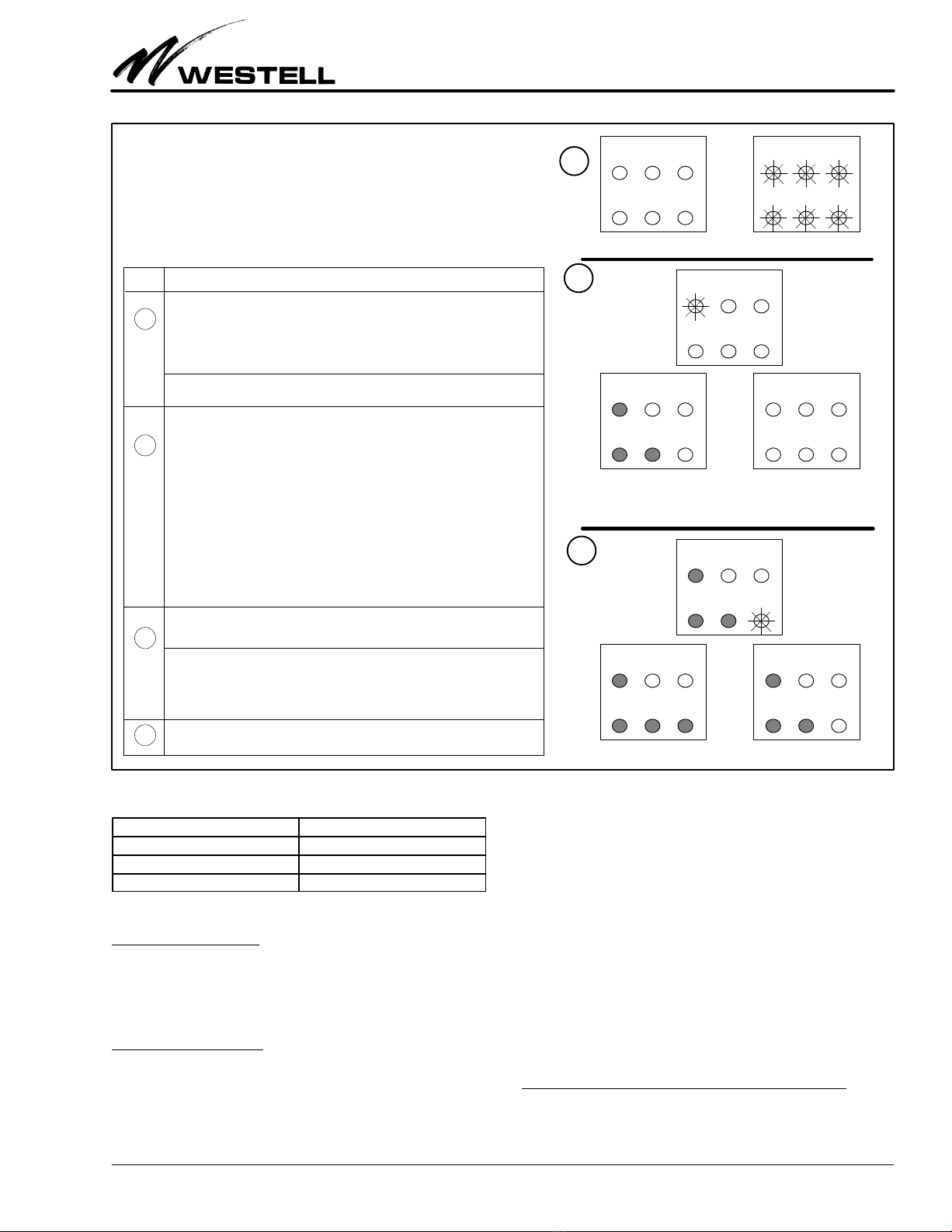
4.3.1 CLOS ID Provisioning − NIU Mode Only
The unit, when configured as an NIU, can be optioned for one
of the following responses upon detecting a CPE loss of signal:
1) to send an AIS toward the Network; 2) to send a Customer
Disconnect Indication (CDI) toward the Network or 3) to enter
Loopback.
To provision the unit for the proper CLOS ID response, option
switch S4 (segments A and B) must first be set to the appropriate
positions (see Figure 16). When S4-A and S4-B are set and while
the CLOS ID LED is flashing, press the front-panel MLB button
within the 4-second time frame. If pressed, the CLOS ID LED
illuminates and the unit sequences to the next Provisioning LED
− ESF Only. If the MLB button is not pressed during the 4-sec-
ond time frame, the CLOS ID option is disabled and the unit
then sequences to the next Provisioning LED − ESF Only.
- NOTE -
If the CLOS ID option is disabled, upon detecting a loss of signal
from the CPE end, the unit simply terminates.
4.3.2 ESF Only Provisioning − NIU Mode Only
- NOTE -
When configured as an Office or as a Line Repeater, the ESF Only
option is not applicable. This feature is available only while in the
NIU mode.
When configured for the NIU mode, the unit can be configured
to respond to SF or ESF codes or respond to ESF codes only.
ESF While the ESF Only LED is flashing, simply press
Only MLB button once to configure unit to detect ESF sig-
nals only. The ESF Only LED illuminates and
sequence to the next LED − NET REGEN.
To configure the unit to detect either SF or ESF codes,
simply let the 4-second timer time out (i.e., do not
press MLB button). ESF Only LED is OFF and the
unit sequences to the next LED − NET REGEN.
- NOTE -
When configured for detecting both SF or ESF codes, the unit
responds to the standard SF or ESF inband loop-up codes 11000 or
0001 0010 1111 1111 and standard loop-down codes 11100 or 0010
0100 1111 1111. If configured for ESF Only, the unit only responds
to the standard ESF DL codes 0001 0010 1111 1111 (loop-up) or
0010 0100 1111 1111 (loop-down).
4.3.3 NET REGEN Provisioning − NIU Mode Only
- NOTE -
When configured as an Office Repeater, Network-side Regeneration
(NET REGEN) is always enabled. Therefore the next Provisioning
LED to flash in the Office Repeater mode, is the CPE REGEN LED.
When configured as a line repeater, the Network and CPE-side
Regeneration (NET and CPE REGEN) options are always enabled
and those LEDs are illuminated. Therefore, the next Provisioning
LED to flash in the Line Repeater mode is the LPBK T.O. LED.
In the NIU mode, the unit can be configured to enable or dis-
able the Network-side Regenerator. When CPE to NET
REGEN is enabled, the unit places a signal regenerator in the
RCV From CPE (Side 2) transmission path. When NET RE-
GEN is disabled, the unit removes the regenerator in the RCV
From CPE (Side 2) transmission path and the unit is passive.
NET While the NET REGEN LED is flashing, to enable
REGEN Network-side regeneration, simply press MLB button
once. The NET REGEN LED illuminates then se-
quences to the next LED − CPE REGEN.
If Network regeneration is not required, simply let the
4-second timer time out. The NET REGEN LED is off
and the unit sequences to the next LED − CPE RE-
GEN.
4.3.4 CPE REGEN Provisioning − NIU Mode Only
In the NIU mode, the unit can be configured to enable or dis-
able the CPE-side Regenerator. When the NET to CPE
REGEN is enabled, the unit places a CPE-side signal regenera-
tor in the RCV from NET (Side 1) transmission path. When
NET to CPE REGEN is disabled, the unit removes the regen-
erator in the RCV from NET (Side 1) transmission path and
the unit is passive.
CPE While the CPE REGEN LED is flashing, to enable
REGEN CPE−side regeneration, simply press MLB button
once. The CPE REGEN LED illuminates then se-
quences to the next LED − LPBK T.O.
If CPE-side regeneration is not required, simply let the
4-second timer time out. The CPE REGEN LED is off
and the unit sequences to the next LED − LPBK T.O.
- NOTE -
With the CPE REGEN feature enabled, the signal regenerator
recovers signals from the CPE and regenerates the DS1 signal
towards the Network at a 0dB level.

Section 520-10S-WI3-203
030-101591 Rev. B
R
11
0806I3RB
STEP ACTION
Local Provisioning Mode
The Craft can provision the unit to operate as an NIU by pressing the
front-panel MLB button and holding it in for 7 seconds or until the 6
front-panel LEDs flash once indicating Local Provisioning mode.
Upon releasing the MLB button, the front-panel PWR/RPTR LED
begins flashing for approximately 4 seconds.
NIU Mode of Operation
If NIU mode of operation is desired, do not press the MLB button.
The PWR/RPTR LED is OFF. Unit sequences to the next Provi-
sioning LED −CLOS ID.
CPE Regeneration ON/OFF
CPE RGN LED flashes for 4 seconds. If CPE-side regeneration is de-
sired, press the MLB button once. CPE RGN LED illuminates. Unit se-
quences over to the next Provisioning Option.
If regeneration is not required, do not press the MLB button. CPE RGN
LED is OFF. Unit sequences to the next Provisioning LED −LPBK TO.
Loopback Timeout ON/OFF
The LPBK TO LED flashes for 4 seconds, press the MLB button once
to enable the 120-minute automatic timeout feature. The LPBK TO LED
illuminates.
To disable the 120-minute automatic loopback timeout feature, do not
press the front-panel MLB button. The LPBK TO LED is OFF.
The 520-10SWI3 is now configured for service as an NIU.
1
2
3
4
5
PWR
RPTR
CLOS
ID
ESF
ONLY
NET
RGN
CPE
RGN
LPBK
TO
PWR
RPTR
CLOS
ID
ESF
ONLY
NET
RGN
CPE
RGN
LPBK
TO
PWR
RPTR
CLOS
ID
ESF
ONLY
NET
RGN
CPE
RGN
LPBK
TO
Press MLB switch for >7 sec. All 6 LEDs will flash once
PWR
RPTR
CLOS
ID
ESF
ONLY
NET
RGN
CPE
RGN
LPBK
TO
PWR/RPTR LED OFF =
NIU Mode Enabled
PWR
RPTR
CLOS
ID
ESF
ONLY
NET
RGN
CPE
RGN
LPBK
TO
PWR
RPTR
CLOS
ID
ESF
ONLY
NET
RGN
CPE
RGN
LPBK
TO
PWR
RPTR
CLOS
ID
ESF
ONLY
NET
RGN
CPE
RGN
LPBK
TO
ESF ONLY LED lit steady =
ESF Detection Enabled
ESF ONLY LED OFF =
SF/ESF Detection Enabled
PWR
RPTR
CLOS
ID
ESF
ONLY
NET
RGN
CPE
RGN
LPBK
TO
PWR
RPTR
CLOS
ID
ESF
ONLY
NET
RGN
CPE
RGN
LPBK
TO
PWR
RPTR
CLOS
ID
ESF
ONLY
NET
RGN
CPE
RGN
LPBK
TO
LPBK TO LED lit steady =
LPBK Timeout Enabled
LPBK TO LED OFF =
LPBK Timeout Disabled
1
2
3
4
Set switches S1 and S2 as follows:
For THRU Power −Set S1 to ON −Set S2 to ON
For LOCAL Power −Set S1 to OFF −Set S2 to ON
For SPAN Power −Set S1 to ON −Set S2 to OFF
Set switches S4A and S4B as follows:
For LOOPBACK Upon CLOS −Set S4A to OFF −Set S4B to OFF
For CDI Upon CLOS −Set S4A to ON −Set S4B to OFF
For AIS Upon CLOS −Set S4A to ON −Set S4B to ON
Customer Loss of Signal −CLOS ID Operation
CLOS ID LED begins flashing for 4 seconds. If CLOS ID operation is
desired, press the MLB button once. The appropriate CLOS ID, de-
pending on setting of S4A and S4B, is enabled. The CLOS ID LED
then illuminates. If the MLB button is not pressed, no action is taken
upon detection of a loss of signal from the customer. The CLOS ID
LED is OFF. Unit sequences to the next Provisioning LED −ESF ONLY.
PWR
RPTR
CLOS
ID
ESF
ONLY
NET
RGN
CPE
RGN
LPBK
TO
CLOS ID LED lit steady =
CLOS Option Enabled
PWR
RPTR
CLOS
ID
ESF
ONLY
NET
RGN
CPE
RGN
LPBK
TO
Loopback Code Detection
ESF ONLY LED is flashing for 4 seconds. If detection of ESF codes
only is desired, press the MLB button once. ESF ONLY LED illumi-
nates. If the MLB button is not pressed, the unit responds to either SF
or ESF code detection and the ESF ONLY LED is OFF. Unit se-
quences to the next Provisioning LED −NET RGN.
NET Regeneration ON/OFF
NET RGN LED flashes for 4 seconds. If Network-side regeneration is
desired, press the MLB button once. NET RGN LED illuminates. If the
MLB button is not pressed, no regeneration is inserted and signals
pass through to the CPE unaffected. The NET RGN LED is OFF. Unit
sequences to the next Provisioning LED −CPE RGN.
6
PWR
RPTR
CLOS
ID
ESF
ONLY
NET
RGN
CPE
RGN
LPBK
TO
5PWR
RPTR
CLOS
ID
ESF
ONLY
NET
RGN
CPE
RGN
LPBK
TO
6
7
NET RGN LED lit steady =
Net-side Regen Enabled
CPE RGN LED lit steady =
CPE-side Regen Enabled
NET RGN LED OFF =
Net-side Regen Disabled
CPE RGN LED OFF =
CPE-side Regen Disabled
7
8
Set switches S3 and S6 as follows:
For NET −XMT LBO −Set S3 to ON for 7.5dB in XMT path
Set S3 to OFF for 0dB in XMT path
For CPE −RCV LBO −Set S6 to ON for 7.5dB in RCV path
Set S6 to OFF for 0dB in RCV path
Figure 11. Quick Optioning Information for NIU Applications

Section 520-10S-WI3-203 030-101591 Rev. B R
12 0806I3RB
47
41
13
75
15
55
49
Figure 12. Single Loopback Operation Diagram − Office Repeater Mode
DSX-1
520-10SWI3
(as Office Rptr)
Fiber Multiplexer
NET
(DSX) AIS CPE
(SPAN)
47
41
13
75
15
55
49
Figure 13. Dual Loopback Operation Diagram − Office Repeater Mode
DSX-1
520-10SWI3
(as Office Rptr)
Fiber Multiplexer
NET
(DSX)
CPE
(SPAN)
4.3.4.1 Loopback Timeout Option
See Paragraph 5.1.2 for loopback timeout enable/disable details.
5. LOOPBACK
The primary function of the 520-10SWI3 is loopback. The
520-10SWI3 supports both manual and remote loopback func-
tions and for both the Network side (single loopback) and the
CPE side (dual loopback). Single loopback allows for looping
the signal received from the Network on Side 1 (RCV From
NET) back to the Network on Side 2 (XMT To NET). The dual
loopback feature allows for looping the signal received from
the Customer on Side 2 (RCV From CPE) back to the Custom-
er on Side 1 (XMT To CPE). Signal regeneration is provided in
both the single and dual loopback transmission paths. Also,
while in the single loopback mode, the unit sends an AIS to-
ward the CPE. The following paragraphs describe the loopback
operations for each operating mode of the unit.
5.1 Manual Loopback - All Modes (Line Repeater,
Office Repeater, and NIU)
Manual (or local) activation of the loopback circuit is achieved
while on site by momentarily pressing the front-panel MLB
button for three seconds but less than five seconds.
- NOTE -
If the front-panel MLB button is pressed for longer than five seconds
but less than seven seconds, the unit enters the Dual Loopback mode
of operation. If the MLB button is pressed for longer than seven
seconds, the unit enters the Local Provisioning mode of operation.
When the MLB button is pressed and released within the 3 to
5-second time frame, the LPBK LED illuminates and a perma-
nent loopback (i.e., no timeout) is established. Manual
Loopback remains in effect until the MLB button is pressed a
second time or the loopback deactivate code is received.
5.1.1 Manual Dual Loopback
Manual activation for dual loopback is achieved while on site
by momentarily pressing the front-panel MLB button for
approximately five seconds but less than seven seconds.
- NOTE -
If the front-panel MLB button is pressed for less than the 5-second
time frame, the unit either returns to normal operation (if the unit is
already in the single loopback mode) or activates the single loopback
mode (if the unit is in the normal operating mode). If the MLB button
is pressed for longer than the 7-second time frame, the unit enters the
Local Provisioning mode.
5.1.2 Loopback Timeout Option
The 520-10SWI3 supports both single and dual loopback op-
eration. The unit also provides an automatic 120-minute
loopback timeout feature that can be either enabled or dis-
abled. To enable Loopback Timeout (LPBK T.O.):
LPBK While the LPBK TO LED is flashing, and if loopback
T.O. timeout is desired, simply press MLB button once. The
LPBK T.O. LED illuminates. The unit is now config-
ured and returns to normal operation.
If Loopback Timeout is not desired, simply let the

Section 520-10S-WI3-203
030-101591 Rev. B
R
13
0806I3RB
4-second timer time out. The LPBK T.O. LED remains
off and the unit returns to normal operation.
5.1.3 Manual Loopback Timeout Disable
The 120-minute Loopback Timeout feature can be disabled lo-
cally, if required, via the front-panel MLB button and using the
Local Provisioning feature (see Sections 4, 6, and 7).
5.1.4 Manual Loopback Deactivation During CLOS
When CPE Loss Of Signal (CLOS ID) is set for Loopback (i.e.,
LPBK Upon CLOS, NIU Mode) and if the unit enters this con-
dition because of a loss of signal from the customer, an override
of this condition can be accomplished by pressing the front-
panel MLB button (i.e., less than 3 seconds). In the override
mode, the unit stays in the override mode for three minutes. If
the override mode times out and if the CPE signal is still absent,
the unit returns to the CPE LOS LPBK state. If the override
mode times out and the CPE signal is present, the unit returns
to normal operation.
5.2 Remote Loopback (Office Repeater Mode)
When configured as an office repeater, and when loopback is
activated from the Network side (single loopback), the unit
loops the signal received from the Network on Side 1 back to
the Network on Side 2. At the same time, AIS is sent toward the
CPE. Refer to Figure 12.
In the dual loopback mode (i.e., looping back both the Network
and CPE side), the unit loops the signal received from the Net-
work on Side 1 back to the Network on Side 2 and loops the
signal received from the CPE on Side 2 back to the CPE on Side
1. Refer to Figure 13.
5.2.1 Remote Loopback − Arming
When configured as an office repeater, and before loopback
can be activated, the unit must first be armed. This is accom-
plished by sending the NIU loop-up code 11000 from the
distant end (SSC or Digital Test location) for five seconds mini-
mum or four consecutive patterns of the 16-bit inband ESF
DataLink code 0001 0010 1111 1111 for 16ms.
Upon receiving the appropriate inband code for the specified
time frame, the front-panel LPBK LED begins flashing at 1-sec-
ond intervals.
- NOTE -
The Arming condition remains in effect for a period of 120 minutes.
If no action is taken during this 120-minute time frame, the unit times
out and returns to normal operation.
5.2.2 Remote Loopback Activation
When the unit is armed, actual loopback activation is accom-
plished by sending the 16-bit inband code 1100 1010 1111 0011
(CAF3 HEX) for a minimum of five seconds to the Side 1 input
transmission path.
- NOTE -
16-bit inband code can be sent in either unframed, SF or ESF formats.
After receiving the 16-bit inband code for the specified time
frame, the front-panel LPBK LED illuminates and the
120-minute Loopback Timeout feature (if enabled) is acti-
vated. At the same time, AIS is sent toward the CPE indicating
the unit is in the single loopback mode. After the 120-minute
time frame, loopback automatically releases and the unit re-
turns to normal operation.
- NOTE -
If the 120-minute Loopback Timeout feature is not enabled,
loopback remains in effect until the front-panel MLB button is
pressed or until the loop-down code is received.
5.2.3 Remote Dual Loopback Activation
Before the dual loopback can be activated, the unit must first
be put into the single loopback mode (see paragraphs 5.2.1
through 5.2.2). Once single loopback is established, the dual
loopback mode of operation is accomplished by sending the
16-bit inband code 1100 1010 1111 0010 (CAF2 HEX) for a
minimum of five seconds to the Side 1 transmission path.
- NOTE -
16-bit inband code can be sent in either unframed, SF or ESF formats.
After receiving this 16-bit inband code for the specified time
frame, the front-panel LPBK LED begins flashing and the
120-minute Loopback Timeout feature (if enabled) is activated.
After the 120-minute time frame, loopback automatically re-
leases and the unit returns to normal operation.
- NOTE -
If the 120-minute Loopback Timeout feature is not enabled,
loopback remains in effect until the front-panel MLB button is
pressed or until the loop-down code is received.
5.2.4 Remote Loopback Deactivation
Loopback deactivation is accomplished by sending the NIU
Loop-down code 11100 for five seconds minimum or the 16-bit
ESF DataLink Loop-down code 0010 0100 1111 1111 for a
minimum of 16ms to the Side 1 transmission path. Loopback
can also be deactivated by momentarily pressing the front-pan-
el MLB button or via the 120-minute Loopback Timeout
feature, if enabled.
- NOTE -
16-bit inband code can be sent in either unframed, SF or ESF formats.
5.2.5 Remote Loopback Timeout Disable
While in the Loopback mode of operation (single or dual) and
if the 120-minute Loopback Timeout feature is enabled, the
Timeout feature can be disabled remotely, if required (see
Paragraph 5.1.3 for local loopback timeout disable). Loopback
Timeout Disable is accomplished by sending the 16-bit code
1101 0101 1101 0110 (D5D6 HEX) for a minimum of five sec-
onds to the Side 1 input transmission path. The 120-minute
Loopback Timeout feature is automatically restored after the
unit returns to normal operation.
- NOTE -
The 120-minute Loopback Timeout feature can be permanently
disabled, if necessary, via the front-panel MLB button and the Local
Provisioning feature as described in Section 4 of this document.

Section 520-10S-WI3-203 030-101591 Rev. B R
14 0806I3RB
47
41
13
75
15
55
49
Figure 14. Single Loopback Operation Diagram − Line Repeater Mode
DSX-1
Fiber Multiplexer
NET
(DSX)
CPE
(SPAN)
47
41
13
75
15
55
49
520-10SWI3
(as Line Rptr)
AIS
NET
(SPAN)
47
41
13
75
15
55
49
Figure 15. Dual Loopback Operation Diagram − Line Repeater Mode
520-10SWI3
(as Line Rptr)
CPE
(SPAN)
47
41
13
75
15
55
49
DSX-1
Fiber Multiplexer
NET
(DSX)
NET
(SPAN)
5.3 Remote Loopback (Line Repeater Mode)
When configured as a line repeater, and loopback is activated
from the Network side (single loopback), the unit loops the sig-
nal received from the Network on Side 1 back to the Network
on Side 2. At the same time, AIS is sent toward the CPE. The
loopback path is provided with signal regeneration. Refer to
Figure 14.
In the dual loopback mode (i.e., looping back both the Network
and CPE side of the unit), the unit loops the signal received from
the Network on Side 1 back to the Network on Side 2 and loops
the signal received from the CPE on Side 2 back to the CPE on
Side 1. Both loopback paths are provided with signal regenera-
tion. Refer to Figure 15.
5.3.1 Remote Loopback − Arming
When configured as a Line Repeater, and before loopback can
be activated, the unit must be armed. This is accomplished by
sending the NIU loop-up code 11000 from the distant end (SSC
or Digital Test location) for a minimum of five seconds or four
consecutive patterns of the 16-bit ESF DataLink code 0001
0010 1111 1111 for a minimum of 16ms.
Upon receiving the appropriate inband code for the specified
time frame, the front-panel LPBK LED begins flashing at 1-sec-
ond intervals.
- NOTE -
The Arming condition remains in effect for a period of 120 minutes.
If no action is taken during this 120-minute time frame, the unit times
out and returns to normal operation.
5.3.2 Remote Loopback Activation
When the unit is armed, actual loopback activation is then ac-
complished by sending the 16-bit inband code 1100 1010 1111
0001 (CAF1 HEX) for a minimum of five seconds to the Side
1 transmission path.
After receiving the code for the specified time frame, the front-
panel LPBK LED illuminates and the 120-minute Loopback
Timeout feature (if enabled) is activated. At the same time, AIS
is sent toward the CPE. After the 120-minute time frame, loop-
back automatically releases and the unit returns to normal
operation.
- NOTE -
If the 120-minute Loopback Timeout feature is not enabled,
loopback remains in effect until the front-panel MLB button is
pressed or until the loop-down code is received.
5.3.3 Remote Dual Loopback Activation
Before the dual loopback can be activated, the unit must first
be put into the single loopback mode (see paragraphs 5.3.1
through 5.3.2). Once single loopback is established, dual loop-
back is accomplished by sending the 16-bit inband code 1100
1010 1111 0010 (CAF2 HEX) for a minimum of five seconds to
the Side 1 transmission path.
- NOTE -
16-bit inband code can be sent in either unframed, SF or ESF formats.
After receiving this 16-bit inband code for the specified time
frame, the front-panel LPBK LED begins flashing and the
120-minute Loopback Timeout feature (if enabled) is acti-

Section 520-10S-WI3-203
030-101591 Rev. B
R
15
0806I3RB
vated. After the 120-minute time frame, loopback
automatically releases and the unit returns to normal opera-
tion.
- NOTE -
If the 120-minute Loopback Timeout feature is not enabled,
loopback remains in effect until the front-panel MLB button is
pressed or until the loop-down code is received.
5.3.4 Remote Loopback Deactivation
Loopback deactivation is accomplished by sending the NIU
Loop-down code 11100 for five seconds minimum or four con-
secutive patterns of the 16-bit ESF DataLink Loop-down code
0010 0100 1111 1111 for 16ms to the Side 1 transmission path.
Loopback can also be deactivated by momentarily pressing the
front-panel MLB button or via the 120-minute Loopback
Timeout feature, if enabled.
- NOTE -
16-bit inband code can be sent in either unframed, SF or ESF formats.
5.3.5 Remote Loopback Timeout Disable
While in the Loopback mode of operation (single or dual) and
if the 120-minute Loopback Timeout feature is enabled, the
Timeout feature can be disabled remotely, if required (see
Paragraph 5.1.3 for local loopback timeout disable). Loopback
Timeout Disable is accomplished by sending the 16-bit code
1101 0101 1101 0110 (D5D6 HEX) for a minimum of five sec-
onds to the Side 1 input transmission path. The 120-minute
Loopback Timeout feature is automatically restored after the
unit returns to normal operation.
- NOTE -
The 120-minute Loopback Timeout feature can be permanently
disabled, if necessary, via the front-panel MLB button and the Local
Provisioning feature as described in Section 4 of this document.
5.4 Remote Loopback (NIU Mode)
When configured as an NIU, and loopback is activated from
the Network side (single loopback), the unit loops the signal re-
ceived from the Network on Side 1 back to the Network on Side
2. At the same time, AIS is sent toward the CPE. The Loopback
path is provided with signal regeneration. Refer to Figure 11a.
In the dual loopback mode (i.e., looping back both the Network
and CPE side, the unit loops the signal received from the Net-
work on Side 1 back to the Network on Side 2 and loops the
signal received from the CPE on Side 2 back to the CPE on Side
1. Both loopback paths are provided with signal regeneration.
Refer to Figure 11b.
5.4.1 Remote Loopback Activation (NIU Mode)
Loopback is accomplished by sending NIU loop-up code 11000
from the distant end (SSC or Digital Test location) for a mini-
mum of five seconds or four consecutive patterns of the 16-bit
ESF DataLink code 0001 0010 1111 1111 for a minimum of
16ms to the Side 1 transmission path.
- NOTE -
16-bit inband code can be sent in either unframed, SF or ESF formats.
After receiving the code for the specified time frame, the front-
panel LPBK LED illuminates and the 120-minute Loopback
Timeout feature (if enabled) is activated. At the same time, an
all 1s AIS is sent toward the CPE. After the 120-minute time
frame, loopback automatically releases and the unit returns to
normal operation.
- NOTE -
If the 120-minute Loopback Timeout feature is not enabled,
loopback remains in effect until the front-panel MLB button is
pressed or until the loop-down code is received.
5.4.2 Remote Dual Loopback Activation (NIU Mode)
Before the dual loopback can be activated, the unit must first
be put into the single loopback mode (see paragraph 5.4.1).
Once single loopback is established, dual loopback is accom-
plished by sending the 16-bit inband code 1100 1010 1111 0010
(CAF2 HEX) for a minimum of five seconds to the Side 1 trans-
mission path.
- NOTE -
16-bit inband code can be sent in either unframed, SF or ESF formats.
After receiving this code for the specified time frame, the
front-panel LPBK LED flashes and the 120-minute Loopback
Timeout feature (if enabled) is activated. After the 120-minute
time frame, loopback automatically releases and the unit re-
turns to normal operation.
- NOTE -
If the 120-minute Loopback Timeout feature is not enabled,
loopback remains in effect until the front-panel MLB button is
pressed or until the loop-down code is received.
5.4.3 Remote Loopback Deactivation (NIU Mode)
Loopback deactivation is accomplished by sending the NIU
loop-down code 11100 for five seconds minimum or four con-
secutive patterns of the 16-bit ESF DataLink loop-down code
0010 0100 1111 1111 for 16ms to the Side 1 transmission path.
Loopback can also be deactivated by momentarily pressing the
front-panel MLB button or via the 120-minute Loopback
Timeout feature, if enabled.
- NOTE -
16-bit inband code can be sent in either unframed, SF or ESF formats.
5.4.4 Remote Loopback Timeout Disable (NIU Mode)
While in Loopback (single or dual) and if the 120-minute Loop-
back Timeout feature is enabled, the Timeout feature can be
disabled remotely, if required (see Paragraph 5.1.3 for local
loopback timeout disable). Loopback Timeout Disable is ac-
complished by sending the 16-bit code 1101 0101 1101 0110
(D5D6 HEX) for five seconds minimum to the Side 1 transmis-
sion path. The 120-minute Loopback Timeout feature is
automatically restored after the unit returns to normal opera-
tion. See Paragraph for local/manual loopback timeout disable.
- NOTE -
The 120-minute Loopback Timeout feature can be permanently
disabled, if necessary, via the front-panel MLB button and the Local
Provisioning feature as described in Section 4 of this document.
5.4.5 Remote Loopback Deactivation During CLOS
When the CPE Loss Of Signal (CLOS ID) operation is optioned
for Loopback (i.e., LPBK Upon CLOS) and if the unit enters

Section 520-10S-WI3-203 030-101591 Rev. B R
16 0806I3RB
S4A S4B
S3S6
S2 S1
OPERATIONAL MODE
S2 S1
ON ON THRU (NIU/RPTR)
ON OFF LOCAL (NIU/RPTR)
OFF ON SPAN (NIU/RPTR)
OFF OFF OFFICE REPEATER
NET −XMT LBO CPE −RCV LBO
7.5dB 7.5dB
CUSTOMER LOS OPTION
S4A S4B
ON ON AIS
ON OFF CDI
OFF ON (NOT USED)
OFF OFF LOOPBACK
MLB
S5
PWR LPBK ALM
NET CPE
LOS
ESF
OFR RPTR NIU
DROP LINE
DROP LINE
I +
I −
M
O
N
C
P
E
N
E
T
M
O
N
C
P
E
N
E
T
RCV FROM
XMT TO
MLB
CLOS
ID
ESF
ONLY
NET
RGN
CPE
RGN
LPBK
T.O.
PWR
RPTR
520-10SWIss.3
ON
ON
ON
Figure 16. Front Panel and Option Location Diagram of the 520-10SWI3
R
this condition because of a loss of signal from the customer, an
override of this condition can be accomplished by sending the
loop-down code 11100 for five seconds minimum or four consec-
utive patterns of the 16-bit ESF DataLink loop-down code 0010
0100 1111 1111 for 16ms to the Side 1 transmission path. In the
override mode, the unit stays in the override mode for three min-
utes. If the override mode times out and if the CPE signal is still
absent, the unit returns to the CPE LOS LPBK state. If the over-
ride mode times out and the CPE signal is present, the unit
returns to normal operation. See Paragraph 5.1.4 for local/manu-
al loopback deactivation during CLOS.
6. OPTIONS & FRONT PANEL FEATURES
The 520-10SWI3 contains features and switch options located
on the front and side (PCB) panels, as shown in Figure 16 and
as described in the paragraphs that follow.
- NOTE -
Set any/all manual option switches prior to installing the unit.
6.1 Front Panel Features
6.1.1 Monitoring Jacks
The 520-10SWI3 contains monitor jacks which allow the craft-
sperson to monitor the transmit and receive signals to and from
the customer and the network. These jacks are labeled RCV
FROM and XMT TO for monitor, CPE and NET, as shown in
Figure 16.
6.1.2 LEDs
See Figure 9, Figure 10, Figure 11, and Part 4 for information
on the LEDs.
6.1.3 Front Panel MLB Button
S5, labelled MLB on the front-panel, is a pushbutton switch
that allows the craftsperson to controls the manual loopback
function of the 520-10SWI3 and to place the unit into manual
loopback mode. It works in conjunction with other provision-
ing options to control the loopback functions of the unit..

Section 520-10S-WI3-203
030-101591 Rev. B
R
17
0806I3RB
6.2 PCB Option Switches (Side Panel)
The 520-10SWI3 contains six option switches on the PCB to op-
tion the unit for proper operation. The locations of these
options are shown in Figure 16.
6.2.1 S1 & S2 − Operational Mode
S1 and S2 are slide switches that control the operational mode
of the repeater. Settings are shown in Table 5.
S2 S1
ON ON THRU (NIU/RPTR)
ON OFF LOCAL (NIU/RPTR)
OFF ON SPAN (NIU/RPTR)
OFF OFF OFFICE REPEATER
Table 5. Operational Mode
6.2.2 S3 − CPE RCV LBO
S3 is a slide switch that controls the CPE Receive LBO. The set-
tings are either 0 or −7.5dB.
6.2.3 S4A & S4B − Customer LOS Option
S4A and S4B are slide switches that control the Customer LOS
settings. Settings are shown in Table 6.
S4A S4B
OFF OFF LOOPBACK
ON OFF CDI
ON ON AIS
OFF ON (NOT USED)
Table 6. Customer LOS Option
6.2.4 S5 − Manual Loopback Button
See Paragraph 6.1.3.
6.2.5 S6 − NET XMT LBO
S6 is a slide switch that controls the NET Transmit LBO. The set-
tings are either 0 or -7.5dB.
7. INSTALLATION
Installation consists of inspecting the equipment for damage,
following proper safety precautions, mounting the
520-10SWI3 module in the proper slot of the mounting assem-
bly and verifying the presence of power and signalling as
indicated by the status LEDs (see Figure 9 through Figure 11).
- INSPECTION NOTE -
Visually inspect the unit for damages prior to installation. If the
equipment has been damaged in transit, immediately report the ex-
tent of the damage to the transportation company and to Westell (see
Part 6 for telephone number).
CAUTION - STATIC-SENSITIVE
This product contains static-sensitive components! Proper
electrostatic discharge procedures must be followed to
maintain personal and equipment safety. Do not store units
near magnetic, electromagnetic or electrostatic fields. Always
store or ship units in the original static-protective packaging
from Westell. Use anti-static mats when working on units.
- PRECAUTIONARY STATEMENT -
Never install telephone wiring during a lightning storm.
Never install telephone jacks in wet locations unless the jack
is specifically designed for wet locations.
Never touch uninsulated telephone wires or terminals unless
the telephone line has been disconnected at the network
interface.
Use caution when installing or modifying telephone lines.
7.1 Mounting the Module
The 520-10SWI3 is a 200 MECHANICSrmodule that mounts
in a 200- or 400-mechanics-type mounting assembly (or equiva-
lent mounting which matches the pin-out plan of the module).
Before installing the module, set any option switch(es) to the de-
sired position(s). Align the module with the mounting or
assembly card guides above and below the unit and insert as far
as it will go into the slot connector.
- CAUTION -
Use care when installing and removing modules - do not force
a module into place. If a module resists insertion, remove it
and check for obstructions in or near the module’s or shelf’s
connectors and mounting slots. The module may then be
carefully aligned and gently re-inserted.
Pin # Lead Designation Description
7
13
T
R
NET IN (Tip)
NET IN (Ring)
41
47
T1
R1
NET OUT (Tip 1)
NET OUT (Ring 1)
5
15
T1
R1
CPE OUT (Tip 1)
CPE OUT (Ring 1)
55
49
T
R
CPE IN (Tip)
CPE IN (Ring)
35 PWR Power IN (−PWR)
17 GND Ground (+PWR)
27 CH GND Chassis Ground
25 ALM Alarm Out
Table 7. Pin/Lead Designations
7.2 Making Installer Connections
The unit makes electrical connection when installed and proper-
ly seated in the 56-pin card-edge connector of the mounting. Pin
connections are shown in Table 7. No installer connections are
required for the 520-10SWI3 other than inserting the module
into the card-edge connector in the shelf or assembly.
7.2.1 Powering Considerations
The 520-10SWI3 can be powered from the 60mA span current
or from a local, external power source. When the unit is pow-

Section 520-10S-WI3-203 030-101591 Rev. B R
18 0806I3RB
ered from an external power supply, it operates from a voltage
source of ±48Vdc, ±24Vdc or 24 Vac.
The unit’s external power lead is fused and provides an alarm
output (pin 25) for external reporting of a local power alarm.
The front-panel ALM (Alarm) LED illuminates if the power
fuse opens.
7.2.2 Span Current Pin Jacks
The unit is equipped with two sets of span current pin jacks,
designated LINE −I and +I and DROP −I and +I, on the
front panel and provide easy access for the installer.
8. TESTING & TROUBLESHOOTING
8.1 Testing
Testing consists of performing the steps outlined in Table 8.
These procedures are intended only to ascertain proper opera-
tion of the unit. Tests beyond those outlined, or repairs made
beyond replacing a faulty unit, are not recommended and may
void the warranty.
8.2 Troubleshooting
If trouble is encountered, verify all installer connections to the
assembly and check that the CO power fuse is not blown. Also
verify all module connections and option switch settings, and
verify the modules are making a positive connection with the
shelf connector. If trouble persists, replace the suspect unit and
repeat procedures outlined. These procedures are not de-
signed to effect repairs or modifications. Any tests beyond
those outlined herein, or repairs made beyond replacing a
faulty unit, are not recommended and may void the warranty.
9. CUSTOMER & TECHNICAL SERVICES
If technical or customer assistance is required, contact Westell
by calling or using one of the following options:
Voice: (800) 377-8766
email: [email protected]
For additional information about Westell, visit the Westell
World Wide Web site at http://www.Westell.com .
Step Action Results
1. Option and install unit
2. Apply Power
If unit is Span Powered, verify the current at the Span Cur-
rent Test DROP" Points (front panel)
PWR LED is ON
Voltage should be equal to 0.6 Volts (±0.03V) for 60mA
operation
3. Press front-panel MLB button (>3 but <5 sec.) LPBK LED illuminates; Unit enters Network Loopback
4. Send Quasi-Random signal to unit Verify QRSS Test code on RCV pair from unit
5. Press front-panel MLB button again LPBK LED extinguishes; Unit returns to normal
6. Press front-panel MLB button (>5 but <7 sec.) LPBK LED illuminates; Unit enters Dual Loopback
7. Send Quasi-Random signal to unit Verify QRSS Test code on RCV pair from unit
8. Press front-panel MLB button again LPBK LED extinguishes; Unit returns to normal
9. Press front-panel MLB button (>7 sec.) Provisioning LEDs flash once, followed by flashing PWR/
RPTR LED
10. Press front-panel MLB button again (<3 sec.) Flashing PWR/RPTR LED extinguishes; Unit returns to
normal
11. Depending on Mode of Operation:
If set for Office Repeater or Line Repeater Mode
Send loop-up code to unit
Inband − 11000 (>5 sec.)
ESF − 0001 0010 1111 1111 (>16ms)
Send loop-up code to unit a second time
Inband − 11000 (>5 sec.)
ESF − 0001 0010 1111 1111 (>16ms)
If set for Network Interface Unit (NIU) Mode
Send loop-up code to unit
Inband − 11000 (>5 sec.)
ESF − 0001 0010 1111 1111 (>16ms)
LPBK LED flashes; Unit is armed
LPBK LED illuminates; Unit is in Loopback
12. Perform Bit Error Rate (BER) test BER must be within acceptable limits
13. Send loop-down code to unit
Inband − 11100 (>5 sec.)
ESF − 0010 0100 1111 1111 (>16ms)
LPBK LED extinguishes; Unit returns to normal
Table 8. 520-10SWI3 Test Procedures

Section 520-10S-WI3-203
030-101591 Rev. B
R
19
0806I3RB
10. WARRANTY & REPAIRS
10.1 Warranty
Westell warrants this product to be free of defects at the time
of shipment. Westell also warrants this product to be fully func-
tional for the time period specified by the terms and conditions
governing the sale of the product. Any attempt to repair or
modify the equipment by anyone other than an authorized
Westell representative will void the warranty.
10.2 Repair and Return
Westell will repair or replace any defective Westell equipment
without cost during the warranty period if the unit is defective
for any reason other than abuse, improper use, or improper
installation. To return defective equipment, first request a Re-
turn Material Authorization (RMA) number from Westell by
calling or using one of the options shown below. Once an RMA
number is obtained, return the defective unit (freight prepaid),
along with a brief problem description, to the address we will
provide to you when you contact us.
Voice: (630) 375-4211
email: [email protected]
Replacements will be shipped in the fastest manner consistent
with the urgency of the situation. Westell will continue to repair
or replace faulty equipment beyond the warranty period for a
nominal charge. Contact Westell for details.
11. SPECIFICATIONS
11.1 Regulatory/Agency Specifications
The 520-10SWI3 module is designed to meet the following reg-
ulatory, safety, or environmental specifications or
requirements:
SComplies with UL1459
SComplies with Bellcore GR-1089
11.2 Ordering Specifications
To order units, call the telephone number shown in Part 9and
please specify a specific model number shown in Table 9.
Part # Description
520-10SWI3 Model 520-10SW Issue 3, DS1 Digital Network Interface Unit.
CLEI* Code: T1L4HKFDAA. Barcode/ECI: 251610. CPR: F70206.
*CLEI is a trademark of Telcordia Technologies.
Table 9. Ordering and Option Information
11.3 Electrical and Physical Specifications
The electrical and signalling specifications are listed below,
and the physical specifications are shown in Table 10.
A. Line Rate: 1.544Mb/s
B. Insertion Loss: 1.0dB max at 772kHz
C. Line Impedance: 100 Ohms (±20%) at 772kHz
D. Loop-up Code:
Inband (unframed or SF): 11000 (>5 sec.)
ESF DL − 0001 0010 1111 1111 (>16ms);
Note: If the unit is set for the Office Repeater or Line Repeater
Mode, front-panel LPBK LED flashes at a slower rate to indicate
unit is Armed for Loopback activation. Sending the loop-up code
a second time activates the loopback circuit.
E. Loop-Down Code:
Inband (unframed or SF): 11100 (>5 sec.)
ESF DL − 0010 0100 1111 1111 (>16ms)
F. Loopback Timeout: 120-minute automatic timeout
G. Loopback Timeout Disable: Via front-panel MLB (Local
Provisioning) or remotely via code 1101 0101 1101 0110
(D5D6 HEX)
H. Manual Loopback Activation: Press MLB switch >3 sec.,
but <5 seconds, then release (for single loopback); >5
sec., but <7 seconds, then release (dual loopback) front-
panel LPBK LED lights steady; >7 seconds, unit enters
Local Provisioning Mode (Provisioning LEDs flash)
I. Manual Loopback Deactivation: Press MLB switch sec-
ond time (<3 seconds) or by sending loop-down code.
J. Loopback Regeneration: 0 to 30dB loss at 772kHz
K. CPE LOS: Set via the front-panel MLB switch (S5) during
Local Provisioning for AIS, CDI or LPBK; LPBK LED
flashes at a fast rate indicating unit is in a LPBK Upon
CLOS state
L. CPE − RCV LBO: 0dB or 7.5dB
M. NET − XMT LBO: 0dB or 7.5dB
N. Power:
Span Power at 57 to 63mA
Local Power at ±20Vdc to ±56Vdc or 22 to 28Vac
O. DC Voltage Drop (Span Powered): Less than 15Vdc at
60mA
P. Maximum Detect Error Rate: <10−3
Physical Feature U.S. Metric
Height 5.6 in. 14.2 cm
Width 0.7 in. 1.8 cm
Depth 5.9 in. 15 cm
Weight (approx.) 12 oz. 340 g
Operating Temp. -40°to 149°F -40°to 65°C
Humidity 0 to 95% (non-condensing)
Mounting 200 MECHANICSrshelf
Table 10. Physical Specifications
Table of contents
Other Westell Recording Equipment manuals