Westell VirtualEdge VE-2848C-K6 1-RU User manual

Section VE2-848-CK6-20A
R
Equipment Issue A
030-101704 Rev. C, June 2010
1006IARC
E2010 Westell, Inc. All rights reserved. Westellrand VirtualEdgerare registered trademarks of Westell, Inc.
* LGXris a registered trademark of Furukawa Electric North America, Inc. *CLEI is a trademark of Telcordia Technologies. Page 1 of 7
VirtualEdgerVE-2848C-K6 1-RU Combination Panel
with 28 RJ48C Jacks and 6 Keystone Ports
CLEI* Code: NCNYAAMERA
PART # PAGE #
1. GENERAL 1. . . . . . . . . . . . . . . . . . . . . . . . . . . . . . . . . . . .
2. INSTALLATION 2. . . . . . . . . . . . . . . . . . . . . . . . . . . . . . .
3. ACCESSORIES 6. . . . . . . . . . . . . . . . . . . . . . . . . . . . . . .
4. CUSTOMER & TECHNICAL SERVICES 6. . . . . . . . .
5. WARRANTY & REPAIRS 5. . . . . . . . . . . . . . . . . . . . . . .
6. SPECIFICATIONS 6. . . . . . . . . . . . . . . . . . . . . . . . . . . . .
1. GENERAL
1.1 Document Purpose
This practice describes Westell’s VirtualEdgerVE-2848C-K6
Combination Panel with six empty Keystone coupler positions
and 28 RJ48C jacks, shown in Figure 1. Westell offers a variety
of panels, couplers, cables, and other orderable options for ter-
minating services for use with the VE-2848C-K6 panel or with
other panels in the VirtualEdge family. See Table 4 for infor-
mation.
- NOTE -
Hereafter, the Westell VirtualEdge VE-2848C-K6 Universal Pan-
el may be referred to as the panel" or the VE-2848C-K6."
1.2 Document Status
Whenever this practice is updated, the reason will be stated in
this paragraph. Revision B updated Table 1, Figure 3 and Para-
graph 3.4 to show the lacer bar as an included item. Revision C
adds the CLEI code, Table 2, Figure 4, Figure 5, and updates
Figure 1, Table 3, and Paragraph 2.5.2.
1.3 Product Purpose and Description
The VirtualEdge (VE) VE-2848C-K6 is a combination panel
used at the CPE point of demarcation. Signals enter the rear of
the panel via two, 32-pair, female, Amphenol connectors and
pass through to the 28 RJ48C jacks via an internal PCB. Lo-
cated on the left front side of the VE-2848C-K6 is a detachable
LGX*-type panel with 6 Keystone-type empty hole ports or
positions; the exact coupler type and type of service terminated
is determined per company practice and application. Different
types of couplers can be combined or mixed within the
VE-2848C-K6 panel, for flexible configurations and applica-
tions. A circuit identification (ID) card is provided inside a
clear plastic packet, which allows installers to label each cou-
pler and jack position. The VE-2848C-K6 comes equipped
with the components shown in Table 1. Optional features in-
clude couplers, D-rings (Figure 10), and a front tray (Figure 9)
for additional cable management at the front of the
VE-2848C-K6.
Figure 1. Isometric View of VirtualEdge Combination Panel
1.4 Product Mounting
The panels can be rack or wall mounted using the included re-
versible mounting ears (included in the bag of parts). These
ears allow flush or projected positions in both 19" and 23" stan-
dard EIA relay racks, or they can be flipped and repositioned
at the back of the panel for wall-mounting. See Part 2 and
Figure 3 for more detailed mounting information.
Quantity Component Description
1 Panel 1.75 inches (1 RU) high panel with six empty
Keystone-type ports, 28 RJ48C jacks, two 32-
pair female Amphenols at the rear, bottom
surface vent holes, and predrilled holes to
accept optional D-rings and a front cable tray
28 RJ48C jacks Female RJ48C jacks, connected to Amphenol
connectors on panel rear via a PCB
1LGX- type
panel
Detachable LGX-type coupler panel with 6
Keystone coupler positions and 6 blank inserts
2 Mounting
ears
Adjustable/reversible ear for 19 or 23" racks or
for wall-mounting, shipped in bag of parts
1Tray (rear) Built-in cable management tray, with multiple
cable tie-downs, located at rear of front panel
8 Screws Two types; to attach ears to panel and to a rack
1Bag of parts Contains 2 mounting ears, ear/rack mounting
screws, and a ground lug with nut
1ID card Circuit ID card, in a clear plastic packet, for easy
customer or coupler identification
1Lacer bar Lacer or towel bar. U-shaped, 2.34" deep,
16.56" wide, 1/4" diameter, used to lace" and
support cables which are connected at the front
of equipment mounted in 19" racks.
Note: D-rings, front tray, couplers, and cables are optional equipment.
Table 1. VE-2848C-K6 Features and Components
1.5 Applications
To enable a greater variety of service and interface offerings,
service providers are putting more fiber into customer prem-
ises, either with Fiber-to-the-Premise or placing more fiber
multiplexers and IP aggregation devices closer to subscribers.
In business markets, the strong demand for Transparent LAN

030-101704 Rev. C R
Section VE2-848-CK6-20A
21006IARC
and Virtual Private Network services creates numerous ap-
plications for Westell’s VirtualEdge panels. These panels are
intended to be simple, sturdy, and versatile mechanical plat-
forms, used to terminate high-speed Ethernet, fiber, or copper
services in any combination(s). Additional interfaces can also
be installed on a per-circuit basis.
1.6 Product Features
The VE-2848C-K6 panel offers the following features.
D1 Rack Unit (RU) high
D28 RJ48C jacks
DRemovable LGX-type panel with 6 Keystone-type coupler
positions [accepts any combination of RJ45/48 (Cat5e for
Ethernet and DS1), SC/LC (fiber), BNC (DS3) or other
Keystone-type couplers]. Blank hole covers included.
DTwo, 32-pair, female, Amphenol connectors at rear
DMounts on wall or in 19" or 23" relay racks or data cabinets
DAdjustable, reversible, mounting ears
DRear steel tray provides cable support and cable tie-downs
for cables coming from the Network/Telco
DSteel construction
DCircuit identification card with clear plastic packet
DRack mounting hardware included
DLacer or towel bar included
DGround lug, nut, and stud
DOptional couplers, front cable management tray, cable
management D-rings, and combination kits available (see
Table 4)
- PRECAUTIONARY STATEMENT -
Never install telephone wiring during a lightning storm.
Never install telephone jacks in wet locations unless the jack
is specifically designed for wet locations.
Never touch uninsulated telephone wires or terminals unless
the telephone line has been disconnected at the network
interface.
Use caution when installing or modifying telephone lines.
- INSPECTION NOTE -
Visually inspect the unit for damages prior to installation. If the
equipment has been damaged in transit, immediately report the
extent of the damage to the transportation company and to West-
ell (see Part 4 for telephone number).
2 INSTALLATION
The VE-2848C-K6 panel can be mounted on a wall or in 19" or
23" relay racks with standard EIA 1.75" hole spacing. When
rack mounting, the panel can be installed so the front of it is
flush with the front of the rack, or mounted in a projected posi-
tion in the rack. The following paragraphs and Figure 3 provide
further details. Screws to attach the mounting ears to the panel
are provided, as well as screws to mount the panel to a rack.
2.1 Mounting in a 19" Rack
The panel is shipped from the factory pre-assembled. Each
panel is equipped with two, removable, L-shaped, mounting
ears (located in the bag of parts). For 19" rack mounting, the
mounting ear’s short flange attaches to the rack channel.
1. Determine vertical position in rack. Select the vertical
mounting location in the rack. This panel requires one ver-
tical Rack Unit (RU) in a standard Telco relay rack.
2. Remove ears from bag. Locate the bag of parts shipped
with the panel and remove the two L-shaped mounting
ears and the rack mounting hardware. Each ear flange has
several sets of mounting holes in it.
3. Determine horizontal position (shelf projection). The
mounting ears and the panel’s side flanges have several
mounting holes from which to choose, for the desired
amount of projection in the rack. If a projected look or ori-
entation in the rack is desired, the ears should be attached
in the last ear hole position on the panel’s side flanges, so
that the panel will be projected further forward from the
mounting ears. If a flush look in the rack is desired, the
mounting ears should be attached in the first or forward
ear hole position on the panel’s side flanges.
4. Attach long flange of ear to panel. Attach both ears to the
panel in the desired position as determined in the step
above, using the hardware provided. The ear’s long flange
abuts the panel.
5. Attach panel to rack. Lift the panel and attach it to the rack
channels in the correct vertical rack position. Align the
holes in the ear’s short flange with the proper holes in the
rack channels. Insert the provided screws into the aligned
set of holes, then tighten the screws. Repeat for both ears.
2.2 Mounting in a 23" Rack
The panel is shipped from the factory pre-assembled. Each
panel is equipped with two, removable, L-shaped, mounting
ears (located in the bag of parts). For 23" rack mounting, the
mounting ear’s long flange attaches to the rack channel.
1. Determine vertical position in rack. Determine and select
the vertical mounting location in the rack. This panel re-
quires one vertical Rack Unit (RU) in a standard Telco
relay rack.
Figure 2. Dimensions for Rack Mounting
23” Rack Mounting
19.3"
18.3"
17"
1.75"
(1 RU)
17"
23.5"
22.3"
19” Rack Mounting

Section VE2-848-CK6-20A
030-101704 Rev. C
R
3
1006IARC
Figure 3. Mounting Views
19" Rack Mounting
23" Flush Rack Mounting
Wall Mounting
Attach short ear flange to rack channel
Attach panel to ears
D
D
Attach long ear flange to rack channel
D
Attach panel to ears
D
Attach ears to panel, as shown (flip brackets)
D
Mark and pre-drill mounting holes in wall (use keyhole-shaped holes)*
D
Attach panel to wall
D
Long
Flange
(use keyhole-shaped holes)
of Ear
Short
Flange
of Ear
* Can be mounted vertically, if desired.
** For a projected" appearance, bring or mount the panel further forward on the ears.
D-ring
(optional)
Panel mounts flush against front face of channel**
Lacer Bar Mounting
Attach mounting/panel to rack
Attach lacer bar to rack
D
D
Lacer bar*
#12-24 screw
*Alternate type shown
2. Remove ears from bag. Locate the bag of parts shipped
with the panel and remove the two L-shaped mounting
ears and the rack mounting hardware. Each ear flange has
several sets of mounting holes in it.
3. Determine horizontal position (shelf projection). The
mounting ears and the panel’s side flanges have several
mounting holes from which to choose, for the desired
amount of projection in the rack. If a projected look or ori-
entation in the rack is desired, the ears should be attached
in the last, rear-most, ear hole position on the panel’s side
flanges, so that the panel will be projected further forward
from the mounting ears. If a flush look in the rack is de-
sired, the mounting ears should be attached in the first or
forward-most ear hole position on the panel’s side flanges.
4. Attach short flange of ear to panel. Attach both ears to the
panel in the desired projection position as determined in
the step above, using the hardware provided. The ear’s
short flange abuts the panel.
5. Attach panel to rack. Lift the panel and attach it to the rack
channels in the correct vertical rack position. Align the
holes in the ear’s long flange with the proper holes in the
rack channels. Insert the provided screws into the aligned
set of holes, then tighten the screws. Repeat for both ears.
2.3 Mounting on a Wall
The mounting ears can be attached for wall mounting. Follow
local codes and company practices for the proper wall type.
1. Determine position on wall. Select the mounting location
on the approved wall. This panel requires one vertical
Rack Unit (RU) in a standard Telco relay rack.Note that the
panel can be mounted in a vertical position, if desired.
2. Remove ears from bag. Locate the bag of parts shipped
with the panel and remove the two L-shaped mounting
ears and the rack mounting hardware. Each ear flange has
several sets of mounting holes in it.
3. Determine horizontal position (wall projection). The
mounting ears and the panel’s side flanges have several
mounting holes from which to choose, for the desired
amount of projection from the wall. If a more projected
position on the wall is desired (allows greater rear access),
the ears should be attached in the last, rear-most, ear hole
position on the panel’s side flanges. If a less projected posi-
tion on the wall is desired (allows more front access), the
mounting ears should be attached in the first or forward-
most ear hole position on the panel’s side flanges.
4. Attach ears to panel. Attach both ears to the panel in the
desired projection position as determined in the step
above, using the hardware provided.
5. Mark mounting hole locations. Lift and place the panel on
the wall in the desired final position and mark the mount-
ing holes to be drilled in the wall with a marking utensil.
6. Drill holes. Set aside the panel and drill the holes. Do not
make the holes too big.

030-101704 Rev. C R
Section VE2-848-CK6-20A
41006IARC
Figure 4. Ground Lug Stud Location
Ground lug
installs on
inside wall
Ground studs are #10-32,
and are 0.625" apart, on centers
7. Attach panel to wall. Lift the panel and align the holes in
the mounting ears with the drilled holes in the wall, then
insert and tighten the mounting screws (not provided).
- GROUNDING NOTE -
Always follow local safety precautions and standard operating proce-
dures for grounding the equipment when installing, upgrading, repairing
or maintaining equipment. Any instructions or information contained
herein is subordinate to local codes, operating procedures or practices.
2.4 Making Ground Connections
2.4.1 The Westell VE panels are shipped with a ground lug
(in a bag of parts) that accepts a #6 ground wire for wall-mount
applications. The installer should locate the ground lug and
hex-nut from the bag of parts shipped with the panel and install
the lug on the post located on the panel’s inside wall, securing
the lug to the post with the nut (see Figure 3). The installer then
makes an earth/chassis ground connection to the lug using a #6
ground wire, per local local company practice and installation
procedures for equipment grounding and bonding.
2.4.2 If the VE panel is installed in a relay rack, the #6
ground lug and nut is not required, but a bond wire may be used
to connect the VE panel’s chassis to the common ground or
bond for the relay rack or cabinet, per local procedures.
2.5 Making Installer Connections
After the panel is mounted, installer connections can be made
to the VE-2848C-K6, as explained in the paragraphs below.
Refer to Figure 5 as needed.
- CAUTION -
Use care when installing and removing couplers, jacks, and
connectors - do not force into place. If resistance is
encountered, check for debris in or near the coupler or hole.
Then gently re-insert the coupler, jack, or connector.
2.5.1 Installing Couplers
Provided with the VE-2848C-K6 panel is a detachable LGX-
type panel which contains 6 Keystone-type coupler positions
(see Figure 8) equipped with blank hole covers. Order and
install couplers per the specific application, company practice,
or service desired. Follow the steps below to install the couplers
in the panel.
1. Call Westell to order the couplers of choice to insert into
the panel for the specific application (see Table 4).
2. Remove the LGX-type panel by pulling on the two Nylatch
fasteners at the side of the panel.
3. Remove (from the rear) the blank hole cover from the
LGX-type panel’s first Keystone-type hole position.
4. At the rear of the LGX-type panel, align the first coupler
with the first empty hole, angle the back of the coupler
down so its top angled tab fits under the hole’s top edge,
then press the coupler into the hole until it snaps in place.
5. Repeat Steps 3-4 for all couplers to be installed.
6. Re-install the LGX-type panel onto the VE-2848C-K6.
7. Order and use optional D-rings, a lacer bar, or a front tray
(see Part 3) for cable management of any cable slack.
8. Use the circuit ID card to identify all coupler positions.
2.5.2 Connecting Network/Telco Cables
Network/Telco connections are made to the female Amphenol
connectors at the back of the VE-2848C-K6 panel (Figure 6).
See Table 2 for lead designations, pin-outs, and wire colors for
the Amphenol connectors, and to Figure 5 as needed.
1. Prepare upstream connection. Remove the protective
connector insert or cover from the back of the DS1 OUT
connector at the rear of the MUX (or upstream equip-
ment).
2. Connect cable to panel’s XMT OUT connector. Route a
male, 32-pair, Amphenol cable from the MUX (or up-
stream equipment) to the female, 32-pair, Amphenol
XMT OUT connector at the back of the Westell
VE2848-CK6 panel, then connect the connectors.
Figure 5. Cabling Block Diagram
DS1 Input
1−28
1−28
A90-VE2848CK6
DS1 Jack Panel
28 DS1
DS1 Output
DS1 MUX RECEIVE
DS1 MUX TRANSMIT
DS1 CPE TRANSMIT
DS1 CPE RECEIVE
MUX
* 32-pair AMP connector
XMT
OUT*
RJ48C
Pins
4 & 5
CSU
RCV
XMT
RCV
IN*
RJ48C
Pins
1 & 2

Section VE2-848-CK6-20A
030-101704 Rev. C
R
5
1006IARC
Circuit
64-Pin
Connector
Pin #
NTWK
RCV-IN
NTWK
XMT-OUT Wire
Color
Reference
Lead RJ48C Lead RJ48C
133 T 5 T1 2 W-BL
1 R 4 R1 1 BL-W
234 T 5 T1 2 W-O
2 R 4 R1 1 O-W
335 T 5 T1 2 W-G
3 R 4 R1 1 G-W
436 T 5 T1 2 W-BR
4 R 4 R1 1 BR-W
537 T 5 T1 2 W-S
5 R 4 R1 1 S-W
638 T 5 T1 2 R-BL
6 R 4 R1 1 BL-R
739 T 5 T1 2 R-O
7 R 4 R1 1 O-R
840 T 5 T1 2 R-G
8 R 4 R1 1 G-R
941 T 5 T1 2 R-BR
9 R 4 R1 1 BR-R
10 42 T 5 T1 2 R-S
10 R 4 R1 1 S-R
11 43 T 5 T1 2 BK-BL
11 R 4 R1 1 BL-BK
12 44 T 5 T1 2 BK-O
12 R 4 R1 1 O-BK
13 45 T 5 T1 2 BK-G
13 R 4 R1 1 G-BK
14 46 T 5 T1 2 BK-BR
14 R 4 R1 1 BR-BK
15 47 T 5 T1 2 BK-S
15 R 4 R1 1 S-BK
16 48 T 5 T1 2 Y-BL
16 R 4 R1 1 BL-Y
17 49 T 5 T1 2 Y- O
17 R 4 R1 1 O-Y
18 50 T 5 T1 2 Y- G
18 R 4 R1 1 G-Y
19 51 T 5 T1 2 Y-BR
19 R 4 R1 1 BR-Y
20 52 T 5 T1 2 Y- S
20 R 4 R1 1 S-Y
21 53 T 5 T1 2 V-BL
21 R 4 R1 1 BL-V
22 54 T 5 T1 2 V-O
22 R 4 R1 1 O-V
23 55 T 5 T1 2 V-G
23 R 4 R1 1 G-V
24 56 T 5 T1 2 V-BR
24 R 4 R1 1 BR-V
25 57 T 5 T1 2 V-S
25 R 4 R1 1 S-V
26 58 T 5 T1 2 W-BL
26 R 4 R1 1 BL-W
27 59 T 5 T1 2 W-O
27 R 4 R1 1 O-W
28 60 T 5 T1 2 W-G
28 R 4 R1 1 G-W
Table 2. 64-Pin Amphenol Connector Wire Colors
Figure 6. Installing Amphenol and RJ48C Cables
Figure 7. Rear View, Connecting Field-provided Cables
32-pair, male
Insert plug of
Amphenol
cables (field-
provided)
field-provided
RJ48C cable
32-pair, male,
Amphenol cables
(field-provided)
3. Perform cable management on the cable per company
practice using the cable tie-downs on the panel’s rear tray.
4. Connect cable to RCV IN connector. Repeat Steps 1-3 for
the MUX (or upstream equipment) DS1 IN connector
and the VE2848-CK6’s female, 32-pair, Amphenol RCV
IN connector.
After installing the cables, when the Network equipment is ac-
tivated, signals from the Network equipment should be present
at the VE-2848C-K6 front panel, where the end-user or cus-
tomer equipment can be connected.
2.5.3 Connecting End-User or Customer RJ48C Cables
Customer connections can be made to the RJ48C jacks at the
front of the VE-2848C-K6 panel. Perform any customer equip-
ment connections per company practice. See Figure 5 if
needed.
1. Route the first RJ48C cable to the first RJ48C jack in the
VE-2848CK-6 and insert the cable’s plug into the jack.
2. Perform cable management per company practice, using
the provided cable tie-downs.
3. Repeat for each jack.
2.5.4 Connecting Other Cable Types
Up to six customer connections can be made to the
VE-2848C-K6 panel at the empty Keystone-type coupler posi-
tions. Perform customer equipment connections per company
practice.
1. Insert the preferred type of Keystone-type coupler into
the first empty Keystone position in the panel (from the
rear, see Figure 8). Remove any cover from the coupler.
2. Route a cable with a matching end plug to the first coupler,
and insert the cable’s plug into the installed coupler.
3. Perform cable management per company practice, using
the provided cable tie-downs.

030-101704 Rev. C R
Section VE2-848-CK6-20A
61006IARC
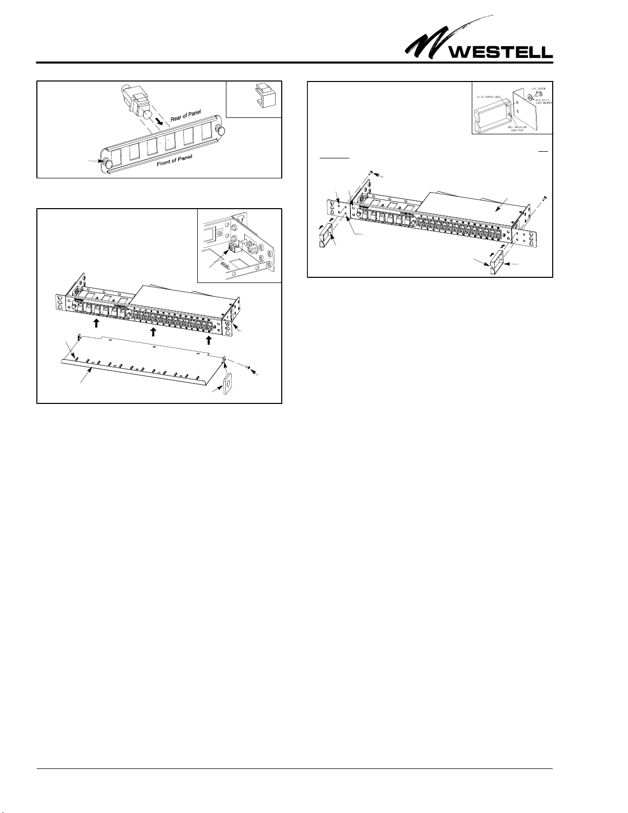
Figure 8. Installing Keystone-type Couplers into LGX Panel
Insert coupler of choice from
the rear of the LGX-type panel.
Depress tab and
insert into hole until
it snaps/locks into place.
Pull Nylatch fasteners
to remove LGX-type
after inserting couplers
Remove
rear of
covers from
blank hole
panel then re-install
LGX-type panel.
Front Tray Flange with hole for mounting
to panel’s inside wall flange
Screw to
Cable tie-down
Attach tray
the inside wall
Figure 9. Installing Front Cable Management Tray
to flange on
1. Locate the two, small, vertical flanges at the inside of the panel
which are used to mount the front tray.
2. Align the front tray’s mounting flange holes with the correspond-
ing holes in the flanges located on the inside of the panel.
(see DETAIL A, rear
3. Insert the provided screws through both holes in the aligned
flanges, and tighten the screws.
4. Secure cables to tray with cable ties at the provided bridge-
forms or cable tie-downs.
view of VE-2848C-K6
for view of flange)
DETAIL A
Flange Rear View
secure tray
to panel
4. Repeat for each couple and cable.
2.5.5 Labelling Circuit Positions
A circuit identification card (label) is provided, inside a clear
plastic packet, for quick and easy circuit labelling and identifi-
cation. The ID card and packet hangs from the panel using the
provided, beaded, removable, cable tie.
3 ACCESSORIES
3.1 Coupler Types
VirtualEdgerpanels and adapter panels accept multiple cou-
pler types (listed below) that can be used or interchanged
within the panel. If desired, couplers can be purchased sepa-
rately using the part numbers shown in Table 4.
SRJ45/48 (Cat5e for Ethernet and DS1 services)
SBNC (for DS3 service)
SSC/LC (for fiber)
SAny Keystone-type coupler
3.2 Front Cable Management Tray
To facilitate cable management at the front of the
VE-2848C-K6, Westell offers a metallic Cable Management
Tray (Figure 9). This tray attaches to the unit as shown in
Figure 9. The tray is designed to allow jumpers and cables to
cross in front of the panel without putting unnecessary down-
1. Pick the set of holes (in panel or ear) to use to mount the D-ring.
2. If installing a D-ring to the holes provided on the right side of the
panel, first remove the protective connector box cover (to access
the rear of the top D-ring hole) from the panel by removing the two
screws on the top surface, one on the left side, and one on the rear.
If any cables are attached at the back side, disconnect them.
3. Align peg (semi-perf) at the back of the D-ring with the bottom
mounting hole in the panel or mounting ear; the peg prevents rotation of the D-ring when properly installed.
4. Align the top hole of D-ring hole with corresponding panel or ear hole and insert the provided screw, from
the back side, through the aligned set of holes (panel and/or ear hole and D-ring hole). Tighten screw.
5. Route cables through slit in the front side of the D-ring. Re-install box and cables, if removed.
F
igure 10. Installing Cable Management D-Rings to the Panel
D-ring
D-ring also can
be mounted here
Insert peg
(peg near bottom of D-ring Slit for
cable access
(optional)
of D-ring here
provides rotational stability)
Peg
D-ring mounting screw
(see
DETAIL A)
DETAIL A
(see DETAIL A)
Protective connector
box cover
ward force or strain on the couplers, when installed. The tray
also has bridge-forms or cable tie-downs to allow technicians to
dress and secure cables to the tray, if desired. The tray can be
mounted to the panels at two different depths to allow custo-
mization based on the amount of cables and jumpers running
across the panels. Use alone or with one or more D-rings de-
scribed in Paragraph 3.3 for a customized cable-management
solution.
3.3 Cable Management D-Rings
Optional, metallic D-rings (Figure 10), for installation at ei-
ther or both ends of a VirtualEdge panel, provide guidance and
support of the cables that run across the front of the panel to
the couplers. In the front of the D-ring, a diagonal slit allows
existing or newly-installed cables/jumpers to be easily inserted
into the ring, without re-feeding or re-routing, and the 3" ring
depth easily accommodates up to 24 or more cables. At the
back of the D-ring, a shallow peg serves as an anti-rotation de-
vice when properly inserted into the bottom hole of the dual
hole-set in the panel or mounting ear. The top, threaded, 10-32
hole at the back of the D-ring accepts the short screw (provided
with the D-ring) that is inserted or threaded from the rear side
of both the D-ring and mounting ear (or panel, if the panel
holes are used). Use one or more D-rings alone or with the tray
described in Paragraph 3.2 for a customized cable-manage-
ment solution.
3.4 Larger Cable Lacer (Towel) Bar
The panel comes equipped with a 16.56" wide, 2.34" deep, lacer
or towel bar installed on the front of the panel (as shown in
Figure 1) to allow cables to be laced around or hung from the
bar for proper support of the cables that connect to jacks or
couplers at the front of the panel. This bar can be used whether
the panel is wall or rack-mounted. Westell also offers an op-
tional, larger, lacer bar (see Table 4) for rack mounting only,
which is 4" deep and 19" wide, and which is installed on the pan-
el’s mounting ears (not on the panel itself). The larger bar can
be used with or without the smaller bar, or with or without op-
tional D-rings. Lace, hang, or tie-down cables around, from, or
at the lacer bar of choice, per company practice.

Section VE2-848-CK6-20A
030-101704 Rev. C
R
7
1006IARC
4. CUSTOMER & TECHNICAL SERVICES
4.1 Customer Service & Technical Assistance
If technical or customer assistance is required, contact Westell
by calling or using one of the following options:
Voice: (800) 377-8766
email: [email protected]
For additional information about Westell, visit the Westell
World Wide Web site at http://www.Westell.com.
4.2 Part Numbers
This equipment is identified by a product number
(A90-VE2848CK6), which consists of three parts: the issue let-
ter of the equipment (A), the assembly type (90), and the
specific model number (VE-2848C-K6). Each time a change is
made to the product which changes the form, fit, or function of
the product, the issue letter is incremented or advanced by one.
Be sure to indicate the issue level as well as the model number
when making inquiries about the equipment.
Feature U.S. Metric
Height 1 .74 in. (1 RU) 4 .42 cm
Width, w/o ears 17 .00 in. (approx.) 43 .18 cm
Width, w/ears in 19" rack
position
19 .20 in. (overall)
18 .31 in. (mounting holes)
48 .77 cm
46 .51 cm
Width, w/ears in 23" rack
position
23 .40 in. (overall)
22 .31 in. (mounting holes)
59 .44 cm
56 .67 cm
Depth (rack-mount) 5 .30 in. 13 .46 cm
Depth (wall-mount, max.) 7 .66 in. 19 .46 cm
Operating Temp. -40°to 167°F -40°to 75°C
Humidity 0 to 95% (non-condensing)
Table 3. Physical Specifications
5. WARRANTY & REPAIRS
5.1 Warranty
Westell warrants this product to be free of defects at the time
of shipment. Westell also warrants this product to be fully
functional for the time period specified by the terms and condi-
tions governing the sale of the product. Any attempt to repair
or modify the equipment by anyone other than an authorized
Westell representative will void the warranty.
5.2 Repair and Return
Westell will repair or replace any defective Westell equipment
without cost during the warranty period if the unit is defective
for any reason other than abuse, improper use, or improper
installation. To return defective equipment, first request a Re-
turn Material Authorization (RMA) number from Westell by
calling or using one of the options shown below. Once an RMA
number is obtained, return the defective unit (freight prepaid),
along with a brief problem description, to the address we will
provide to you when you contact us.
Voice: (630) 375-4457
email: [email protected]
Replacements will be shipped in the fastest manner consistent
with the urgency of the situation. Westell will continue to repair
or replace faulty equipment beyond the warranty period for a
nominal charge. Contact Westell for details.
6. SPECIFICATIONS
The physical specifications are shown in Table 3. To order
units, call the telephone number shown in Paragraph 4.1 and
please specify a specific part number shown in Table 4.
Part # Description
A90-VE2848CK6 VirtualEdgerVE-2848C-K6 1-RU Combination Panel
w/28 RJ48C jacks, a removable LGX-type panel with 6
blank positions for Keystone-type couplers, a lacer bar
and two 32-pair female Amphenol connectors at rear.
CLEI: NCNYAAMERA, Barcode/ECI: 461509, CPR: 214181.
Other Panels, and Panel Accessories and Options*
A90-VEUP30 Model VEUP-30 - VirtualEdger1-RU Universal Con-
nection Panel for LGX-type fiber panels and Keystone
couplers, with 3 LGX-118 to Keystone coupler panels.
A90-VEVP31 Model VEVP-31 - VirtualEdger1-RU Video Panel.
A90-VE1200 12-position, 1-RU high, VirtualEdgerConnectivity panel
with 12 empty coupler termination positions.
A90-VE1212 Model VE-1212 - Same as VE-1200 but equipped with
12 Cat5e couplers.
A90-VE2400 Model VE-2400 - 24-position, 2-RU high, VirtualEdger
Connectivity Panel with 24 empty coupler termination
positions.
A90-VE2424 Model VE-2424 - Same as VE-2400 but equipped with
24 Cat5e couplers.
A90-VE2424SC Model VE-2424SC - Same as VE-2424 but equipped
with 24 SC couplers.
A90-VE2424BNC Model VE-2424BNC - Same as VE-2424 but equipped
with 24 BNC couplers.
A99-VE2424BNC Kit which contains a 24-position panel, 24 BNC
couplers, a cable management tray, 2 D-rings, kit
assembly hardware, and rack mounting hardware.
A99-VE2424SC Same as A99-VE2424BNC but with SC couplers.
A90-VECMTRAY Cable management tray (front projection).
A90-VECMLBAR Lacer or towel bar, 4" deep, 19" wide, 1/4" diameter,
used to lace" and
support cables at
front of panels.
A90-VECMRING3 Cable management
D-ring (Qty = 1).
Includes split
washer and
mounting screw(s). Peg (anti-rotation
semi-perf at rear)
Threaded
Hole
A90-VECPL5E10 CAT 5e RJ48 Keystone
style coupler (Qty = 10)
A90-VECPLBNC10 BNC COAX coupler
(Qty = 10)
A90-VECPLSC1 Fiber coupler with SC
connectors (Qty = 1)
A90-VECPLLC1 Fiber coupler with LC
connectors (Qty = 1)
A90-VECPL5EIDC10 CAT 5e couplers (IDC termination on Network side)
(Quantity = 10)
*A variety of cables and fiber jumpers also are available. Call Westell for details.
Table 4. Ordering and Option Information
This manual suits for next models
1
Table of contents
Other Westell Recording Equipment manuals