1.3 Gas Cooker
Warning ! Before opening the cooker cover, put the driver’s seat in a
vertical position.
When cooking with high heat levels, the more powerful of the cooker hobs
is on the left hand side.
To Switch On:
Open the vents in the cupboard, press the cooker knob in, and turn to the
left. Light the gas with a match or lighter, the press in the cooker knob for
about 10 seconds (to ensure it remains lit). If the flame goes out when you
let go of the knob, repeat the process above for lighting, and hold in the
knob for a little longer.
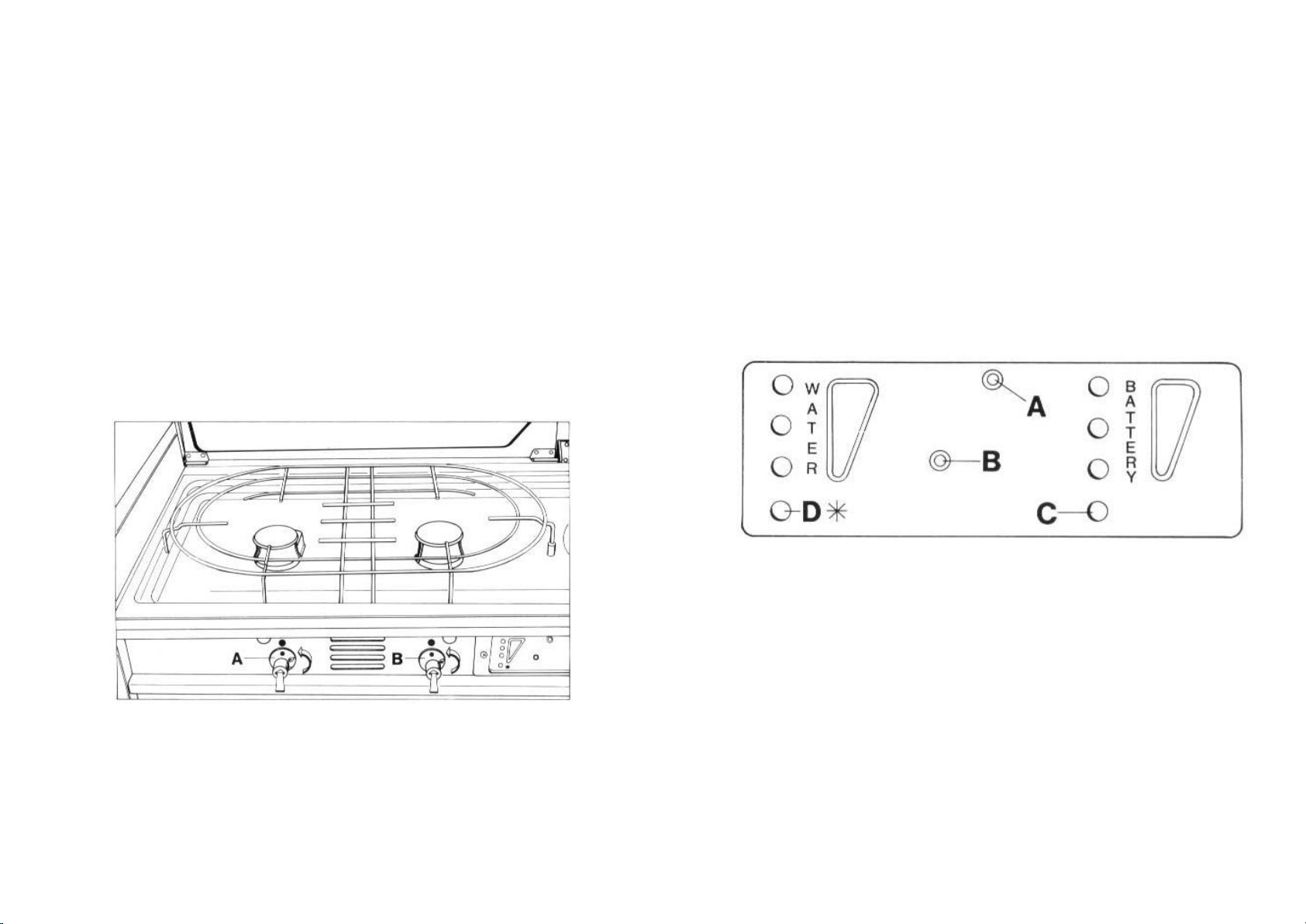
A = Strong Cooker B = Normal Cooker
To Turn Off:
Turn the cooker knob to 0, shut the barrier vent in the cupboard.
Warning ! When using the cooker, the air vents (windows) are
not allowed to be closed. Open sources of heat should not be used
to warm food.
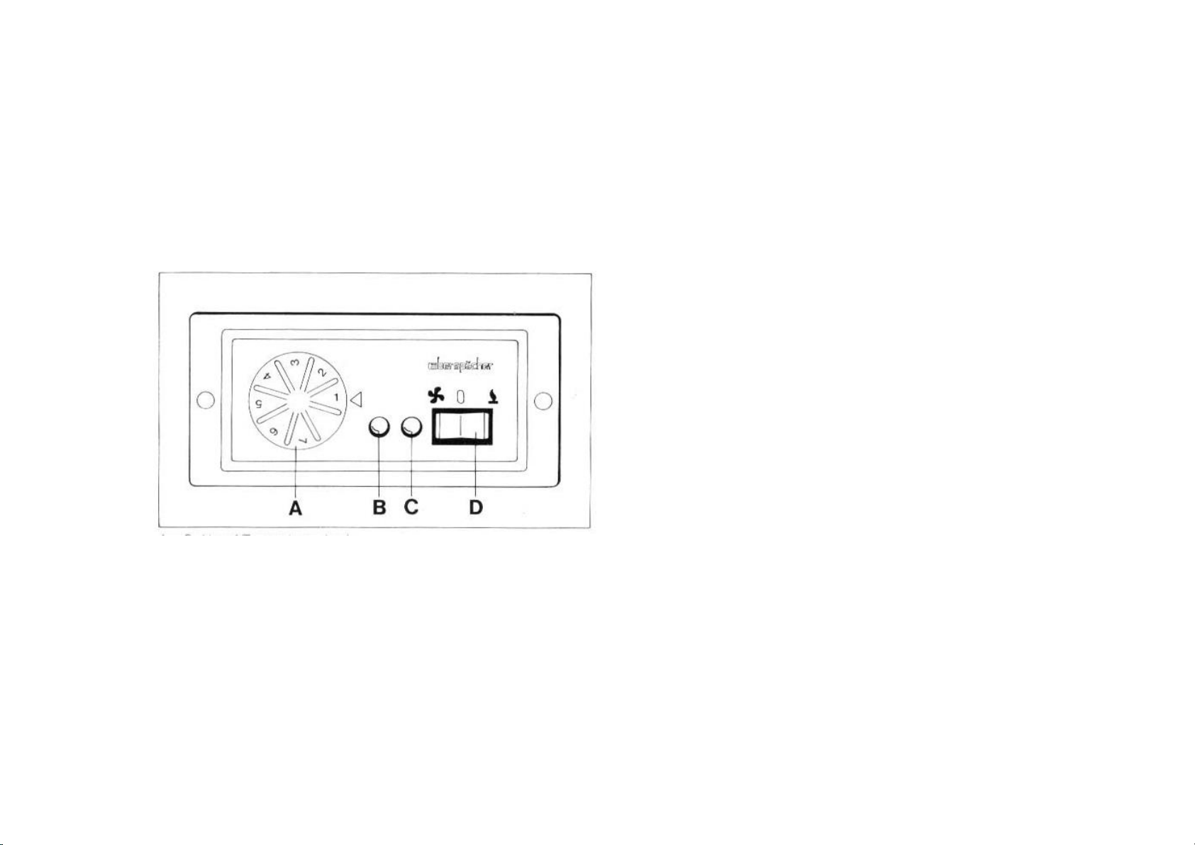
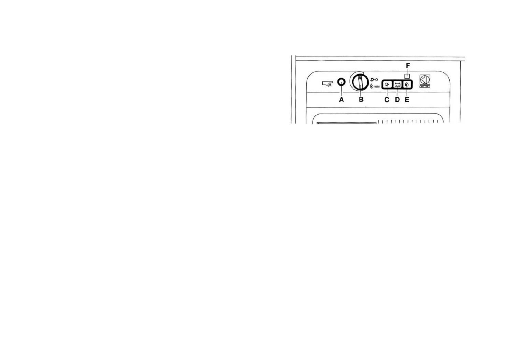
1.4 Display
The cooker contains a display of the functions of:
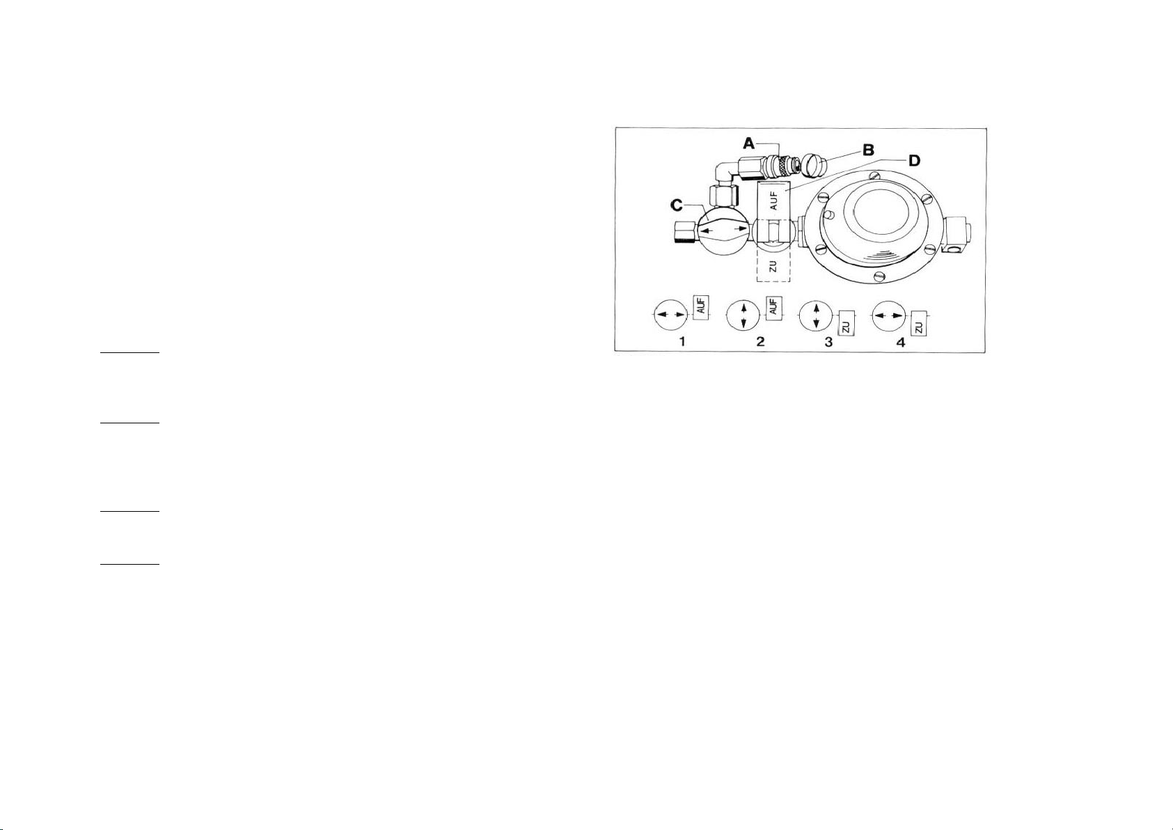
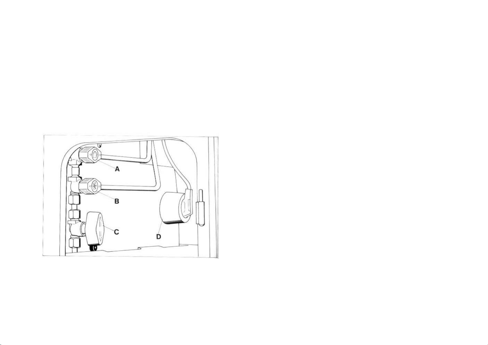
(1) control display for the fridge’s use of gas / petrol
(2) water display of the fresh water tank
(3) second (leisure) battery charge level
(4) switch and LED (Control Lights) for the De-Icer
A = Switch for Control Light for Water, Battery Levels, and
Petrol Usage of fridge
B = Switch De-Icer On/Off
C = Control Light for De-Icer
D = Control Light for Fridge
Switch (A) can be used to switch the control lights for filling the
fresh water tanks, the petrol use of the fridge, and the charge level
of the second battery On/Off.