1
Westin Automotive Products, Inc.
320 W. Covina Blvd
San Dimas, Ca. 91773
Thank you for choosing Westin products
for additional installation assistance please call
Customer Service (800) 793-7846
www.westinautomotive.com
P.N.: 75-5653401-RevA ECO #: W17-0067 DATE: 11/2/17
INSTALLATION INSTRUCTIONS
AUTOMOTIVE PRODUCTS,
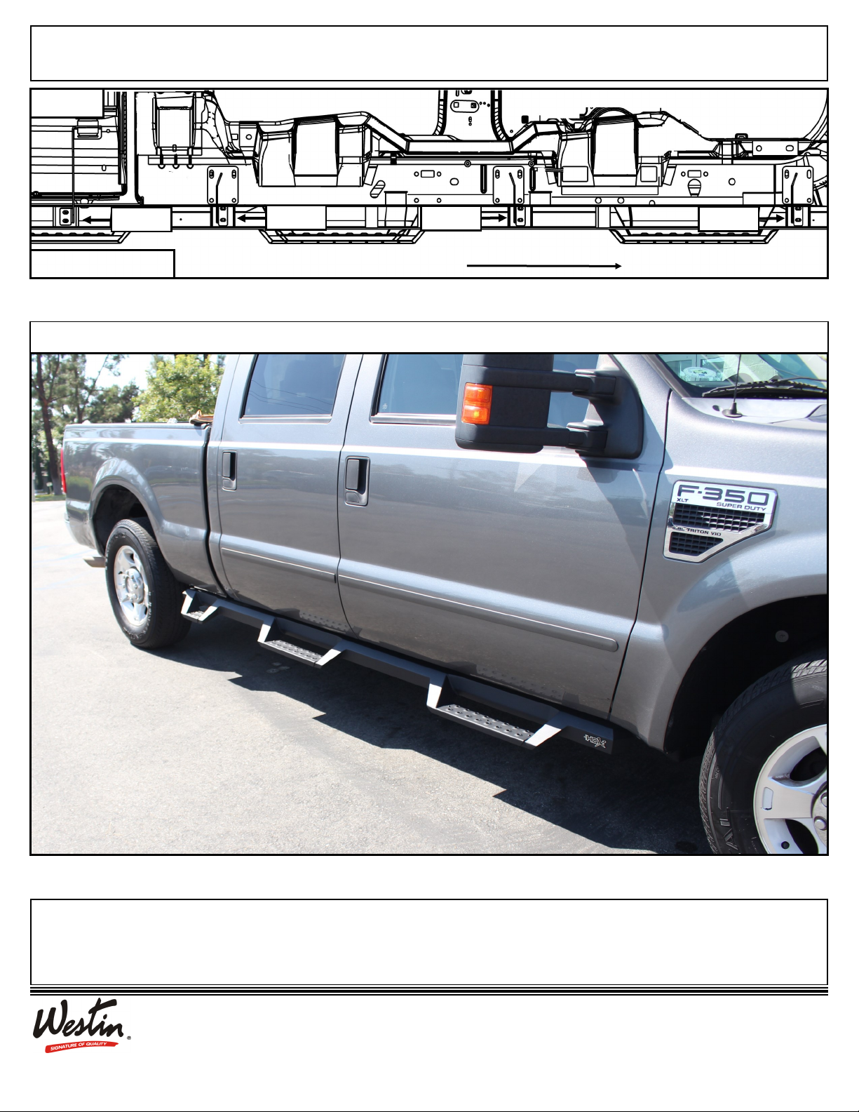
HDX DROP STEP WTW
APPLICATION:
1999-2016 Ford F250 / F350 / F450 / F550 - Super Crew 6 Ft Bed
PART NUMBER:
56-534015, 56-5340152
ITEM QUANTITY DESCRIPTION TOOLS NEEDED
12STEP BAR ASSEMBLY 3/8” DRIVE RATCHET
24MOUNTING BRACKET 1/2” DRIVE RATCHET
31DRIVER SIDE CENTER MOUNTING BRACKET TORQUE WRENCH
41PASSENGER SIDE CENTER MOUNTING BRACKET 13MM SOCKET
52FRONT SPACER PLATE ALLEN WRENCH
610 M8 EXTRUDED U-NUT (ZINC PLATED) SOCKET EXT.
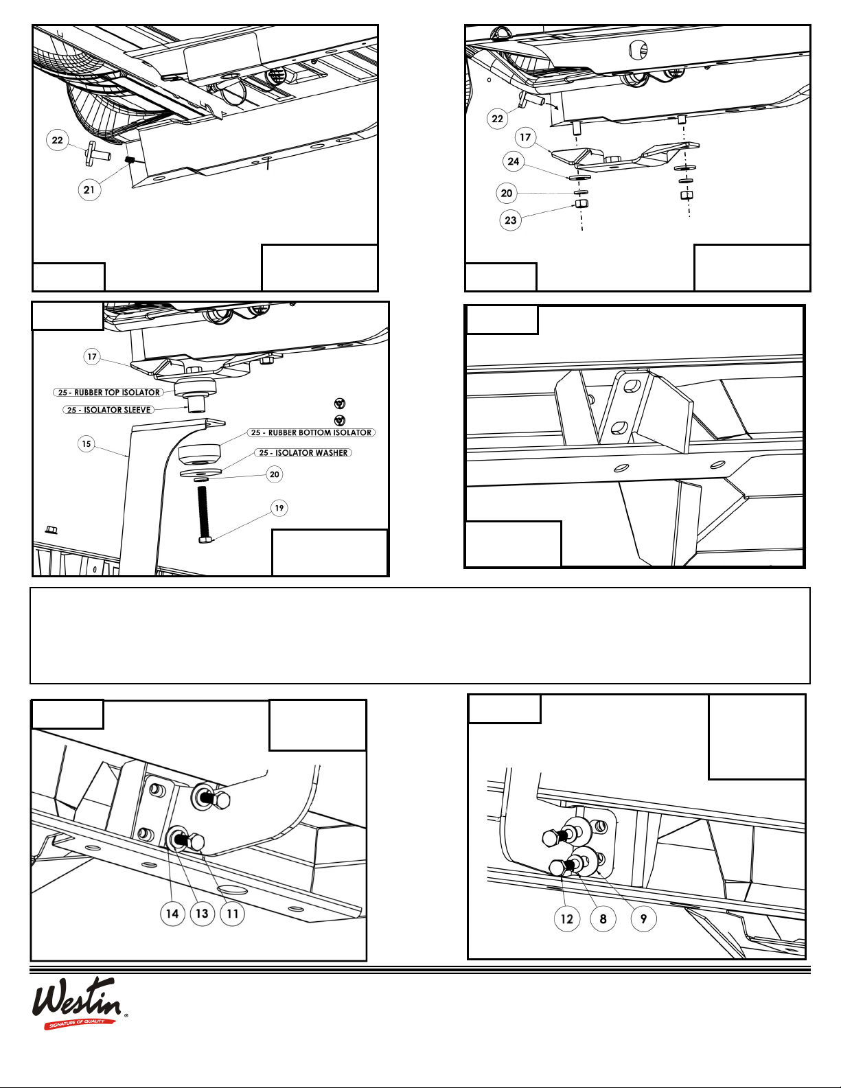
712 M8 HEX NUT (BLACK ZINC) 13MM WRENCH
812 M8 BUTTON HEAD CAP SCREW (BLACK ZINC) 18MM SOCKET
912 M8 SPLIT LOCK WASHER (BLACK ZINC) 19MM SOCKET
10 24 M8 FLAT WASHER (BLACK ZINC) 18MM WRENCH
11 12 SHORT M8 HEX HEAD CAP SCREW (YELLOW ZINC) 19MM WRENCH
12 14 LONG M8 HEX HEAD CAP SCREW (YELLOW ZINC)
13 26 M8 SPLIT LOCK WASHER (YELLOW ZINC)
14 26 M8 FLAT WASHER (YELLOW ZINC)
15,16 2ISOLATOR BRACKET, DRIVER (15) AND PASSENGER (16)
17, 18 2TOP ISOLATOR MOUNT BRACKET, DRIVER (17) AND PASSENGER (18)
19 2M12 HEX HEAD CAP SCREW (YELLOW ZINC)
20 6M12 SPLIT LOCK WASHER (YELLOW ZINC)
21 2M12 FISH WIRE
22 4M12 BOLT PLATE
23 4M12 HEX NUT (YELLOW ZINC)
24 4M12 FLAT WASHER (YELLOW ZINC)
25 2ISOLATOR KIT
ANTI-SEIZE LUBRICANT MUST BE USED ON ALL STAINLESS STEEL FASTENERS TO PREVENT THREAD DAMAGE AND GALLING
CONTENT
ITEM 2 ITEM 3 ITEM 4 ITEM 5ITEM 1