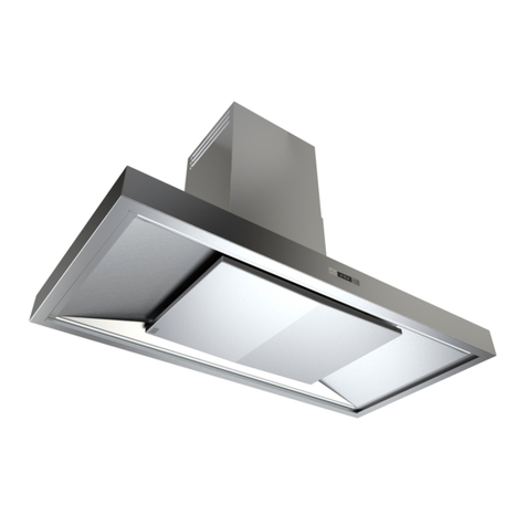
Ceiling Built-in Unit:
EM (Remote Motor Version)
Installation, Operating & Maintenance Instructions
W1558 WSW STRATUS BLADE EM Ceiling Extract O&M Feb 17.docx Page 2 Westin
4. INSTALLATION
The extractor is designed for installation within a cut-out in the
underside of the kitchen ceiling. Alternatively, it may be
installed within a lowered bulkhead or furniture soffit panel, but
remember it is desirable to install directly into the ceiling where
possible (see section 3).
Please note the following:
The extractor comprises of two main parts:
o The “top box”, which houses the duct spigot, hood
electronics and electrical connection points for your
remote motor.
o The “baseplate”, which houses the visible parts of the
product when installed, such as LED light bars, grease
filters, door panel assembly and outer frame.
The Stratus Blade “top box” has 4 possible duct spigot
positions (Left, Right, Front, or Rear).
The ducting spigot must be set to the required outlet
position prior to installation.
The extractor has four hidden fixing holes, accessible via
20mm access holes set into the baseplate corners. These
can only be accessed with the door panel open.
Black cover caps are provided which press into and close
off the fixing hole access points after installation.
4.1. Prepare Your Opening
Prepare the opening into which the unit will be installed.
Unit Size (mm)
(Width x Depth x Height)
Cut-out Size (mm)
(Width x Depth x Height)
1180 x 420 x 200 1160 x 400 x 205
Reinforce the opening as necessary and make sure suitable
provisions are made to take the screws which will hold the unit
in place (see below) and for any ductwork to pass through.
The provisions made for the screws which will support
the extractor:
Must be strong enough to support a total weight of
30Kg.
Must be recessed so that the surface you screw into is
70mm above the finished ceiling surface.
Tip: Because much of the baseplate only intrudes into the
ceiling by 62mm, for installations where the unit runs across
joists or ceiling voids are insufficient, consider whether the
ceiling can be lowered slightly to avoid boxing down or
complex joist alterations.
4.2. Ducting Requirements and Installation
Depending upon your site, ducting may need installing before,
or in conjunction with the preparation of your ceiling opening.
Install ducting, taking note of the advice given in section 2 & 3.
To help with your installation, a 500mm length of rigid
rectangular 220x90mm ducting, a flexible rectangular
220x90mm connector and a flat channel to 150mm round
adaptor are included with your hood.
Not all parts are needed with all installations but unused parts
should only be discarded after the installation is complete.
Regardless of the duct type being used for the majority of
your duct run, you must terminate fixed ducting in the
kitchen with 220x90 flat channel so that the flexible
connector included can be used when installing the
extractor. This is important because these extractors are
usually blind-fitted and must be removable without
disturbing the fixed ductwork should servicing become
necessary. The parts included with the extractor should be
sufficient for you to do this.
For the rest of the duct run, we recommend using rigid flat
channel 220 x 90mm ducting, rigid 150mm round or semi-rigid
150mm round duct, to best suit your particular site conditions.
Proceed as follows:
Cut the 500mm piece of rectangular ducting (included
with extractor) into a 100mm and 400mm long piece.
The 100mm long piece will be used later to connect the
flexible connector to the extractor spigot.
The 400mm long piece can be attached to the round
adaptor if you plan to install round ducting.
Install fixed ducting such that it terminates in the
kitchen with a 220x90 flat channel duct section centred
450mm away from the centre point of the extractor
(see IMPORTANT NOTE below).
If installing round ducting, then the 400mm piece of
rectangular ducting you cut earlier can be used with the
round adaptor to give you your rectangular termination.
Attach the flexible rectangular connector (included
with the extractor) to the rectangular end of your duct,
so it hangs through the ceiling opening, ready for
connection to the extractor during installation.
When terminating ducting on an outside wall, a suitable
weather louvre should be used. Ducting components and
complete kits are available from Westin for most installations.
For roof or chimney duct terminations, please contact Westin
or seek alternative specialist advice.
If you are fitting a wall-mounted external motor with semi-rigid
or flexible ducting, then you must leave a short length (approx.
200mm) of ducting proud of the wall, to enable connection to
the motor spigot before pushing both back flush with the wall.
Dimensioned drawings and illustrations to help with
your installation can be found on page 6 onwards.
Please refer to the drawings on Pages 6 - 8 for the
detailed product design information you will need to
plan and build a suitable opening.
Illustrations showing the ducting arrangement
needed to allow connection of the hood to your
ductwork can be found on pages 7 - 8
IMPORTANT NOTE
If using the front or rear spigot positions, this
means that your 220x90 flat channel duct must
terminate above the finished ceiling and be set
back 250mm from the long edge of your opening.
If using the left or right spigot positions, this means
that your 220x90 flat channel must protrude into
your ceiling opening and terminate 130mm in from
the short edge of your opening.


