Installation, Operating & Maintenance Instructions
W1403 Stratus 360 IOM V1 20150112.docx Page 2 Westin
1. INTRODUCTION
During the cooking process odours are produced which, if left
untreated, can linger for a long time after cooking has ceased.
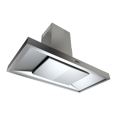
Your Westin Stratus 360 Ceiling built-in unit is a powerful built-
in extractor that has been designed to complement your
kitchen both in looks and performance in order to create a
good environment for creative cooking and is ideal for
applications where a conventional cooker hood is neither
suitable nor desirable.
Featuring the Westin 360 air recirculation technology, many of
the benefits of ducted extraction products are delivered by this
revolutionary duct-free air cleansing system, effectively
removing unwanted odours from your kitchen.
Of course, hygiene is also a priority in any kitchen and your
Westin Stratus 360 not only serves to remove odours but also
actively assists in the destruction of harmful bacteria,
pathogens and allergens which may be present, thus helping
to purify the air.
Your Stratus 360 also benefits from Westins unique LED Light
Blade lighting system, delivering simultaneous ambient and
task lighting to your kitchen.
2. IMPORTANT INFORMATION
Pay particular attention to fire risk when frying. To minimise
the risk of fire, all instructions relating to cleaning the grease
filters and removing grease deposits must be adhered to.
Do not flambé under the extractor.
This product has been designed for installation directly
into your kitchen ceiling or at an otherwise high level so
that the underside of your Stratus 360 is as close to the
ceiling as possible.
Installation at lower levels may result in reduced system
performance and excessive draughts at worktop level on
high fan speeds caused by the close proximity of the air
discharge vents at each end of the product.
Whilst we recommend installation is at ceiling level, if you
do choose to install the product at a lower level (for
example within furniture above your hob) then the
minimum clearance between the top of the hob and the
underside of the Stratus 360 should be within the
following range (unless a greater distance is specified by
your cooking appliance or furniture manufacturer):
hob-to-extractor minimum clearance distances:
450mm above electric hobs and cookers
750mm above gas hobs and cookers, fryers, open grills
850mm above Wok burners, griddles, barbeques.
hob-to-extractor recommended clearance distance:
Flush with or within 300mm of ceiling.
The minimum distance between the hob and the bottom of the
extractor is essential for safety reasons and to prevent
overheating of the extractor and its components.
3. SYSTEM PERFORMANCE
In very simple terms, your Stratus 360 relies on two primary
principals to maximise effectiveness:
Firstly, air is drawn into the perimeter air intake slot
surrounding the central door panel and passes through the
extractor where contaminants are broken down by the 360
system.
The air is then discharged into the room via two discharge
vents at each end of the appliance.
The potency of the contaminants will determine how long it
takes to completely remove odours, with the discharged air
mixing with other air in the room and then being drawn back
through the extractor in a continuous cycle.
This mixing of the air is important and works best when the
unit is installed at a high level, maximising the mixing effect.
Not only that, but warm foul air will rise up and be collected
more effectively at ceiling level. Furthermore, draughts from
the discharge vents are reduced with distance.
The second strategy for tackling odours also relies on effective
mixing of the air in the room. Your Stratus 360 emits super-
oxidants (reactive molecules), via the discharge vents, which
are sent out into the room to react with odour molecules they
encounter. In this way, the Stratus 360 not only works to
reduce airborne contaminants but also those adhering to
surfaces, such as walls.
In summary, overall performance of the system is optimised
when all of the air in the room is free to mix and enter the
appliance unobstructed and the best way to ensure this is to
install the unit at a high level as this will prevent pockets of air
potentially stagnating.
In order to maintain optimal performance, it is important to
follow the cleaning and maintenance instructions in section 7.
In brief, this entails keeping the grease filters and accessible
parts and surfaces clean and ensuring that the Westin 360 air
cleaning module’s special UVC composite lamp is periodically
replaced.
4. INSTALLATION
The extractor is designed for installation within a cut-out in the
underside of the kitchen ceiling. Alternatively, it may be
installed within a lowered section of ceiling (boxed in area) or
into a soffit panel within furniture – remember though that it is
desirable to install directly into the ceiling (see section 5.2).
Please note the following.
The product features a safety cut-out switch and will not
operate with the door in the open position. If you want to
test the appliance prior to installation you should do so with
the door closed.
The Stratus 360 has four fixing holes which are hidden
behind the closed filter concealment panel (door) and are
accessible only when the door is open.
The fixing holes are located in the upper surface of the
side wings (see line drawing in section 5) and are
accessed (for fixing through) via 20mm access holes in the
baseplate. By separating the load bearing and decorative
surfaces in this way means we avoid any visible distortion
to visible areas being caused by your fixings.
Black cover caps are provided which press into and close
off the fixing hole access points after installation.
The door is held shut with magnetic catches.
Open the door by grasping it close to the corners on the
catch side (the long edge opposite the hinges) and pulling
ELECTRICAL SAFETY.
This appliance requires an earth connection.
Ensure that the supply voltage corresponds to that marked on
the rating label inside the extractor.
The extractor must be isolated from the electrical supply before
carrying out any cleaning or maintenance operations.
Dimensioned drawings and illustrations to help with
your installation can be found in Section 5.


