P84577 G
Sheet 5 of 14
4.0 USING THE SP4-APS WITH THE SP40/2
One SP4-APS can be connected to the SP40/2 panel. It is to be mounted inside the panel enclosure onto the backplane in the
upper right hand corner.
4.1 MOUNTING INSTRUCTIONS:(SP40/2)
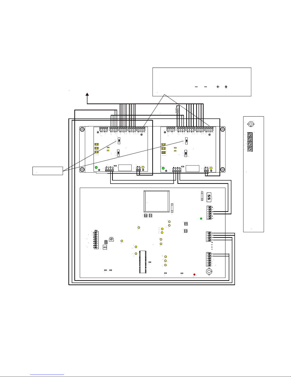
Figure 6 shows the mounting location of the SP4-APS Splitter to the backplane of the SP40/2 panel. Figure 7 shows the
correct mounting procedure.
STATUS
AC TROUBLE ALARM
AUDIBLE
TROUBLE
SILENCE
INDICATIONS
When the GREEN "AC" light is ON, the system is energiz ed.
Whenthe YELLOW"TROUBLE"light is ON, thereis a fault in the system
which MUST BE CORRE CTED.
Whenthe RED"STROBE" light is ON,, the strobe c ircuit is active.
IF THE YELLOW "TROUBLE" LIGHT IS ON, THIS UNIT MAYNOT BE ABLE TO PROVIDE EMERGENCY
MESSAGEANNOUNCEMENT CAPABILITIES AND COULDRESULT IN PROPERTY DAMAGE,SERIOUS INJURY,
OR DEATHTO YOU AND/OR OTHERS. IN THE EVENT THE "TROUBLE" LIGHT IS ON, YOU SHOULD
CONTACTYOUR SE RVICE REPRESENTATIVEIMMEDIATELY.
MICROPHONEOPERATION
1. Hold the microp hone within two inches of t he mouth and press the
push-to-talk switch on the mi crophone.
2. Deliverthe message.Activationof the microphonewill deliver the message
toall circuits.
FOR ADDITIONAL INFORMATION
REFER TO THE OPERATION AND INSTALLATION MANUAL.
BEFOREREMOVINGTHIS PANEL.
CAUTION
DO NOT ATTEMPT TO REMOVE OR R EPLACE
MODULAR PC BOARDS INSIDE WITHOUT
DISCONNEC TING ALL PO WER SOURCES TO
THISUNIT FIRST. FAILURE TO DOSO MAY
RESULT INDAMAGE TOTHE PC BOARDS.
DISCONNECTIN G -
FIRSTDI SCONNECT
BATTERYPOWER AT BATTERYTERMINALS
THEN DISCONNECT AC POWERAT THE
POWER SOURCE.
RECONNECTING -
FIRST RE CONNECT AC
POWERAT TH E POWER SOURCE. THEN
RECONNECTBATTERYPOWER ATTHE BATTERY
TERMINALS .
WARN IN G
BGM
VOLUME
+ -
SP4-APS
MOUNTING STUDS
SP40/2 BACKPLANE
MOUNTING STUDS
COVER STANDOFFS (4)
SP4-APS COVER
MOUNTING SCREW (4)
TOP
RIGHT
SIDE
SP4-APS PC BOARD
Figure 6: Figure 7:
SP4-APS Mounting Location in SP40/2 Enclosure SP4-APS Mounting in SP40/2 Enclosure
1. Position the SP4-APS PC board so that the side with most of the terminal blocks are pointing to the top of the
SP40/2 enclosure and the writing on the PC board can be read. Align the mounting holes on the SP4-APS PC board
with the backplane mounting studs.
2. Using the supplied screws, studs, and standoffs, screw the male end of the 4 cover standoffs through the SP4-APS
PC board and to the 4 mounting studs on the SP40/2 backplane. Tighten all standoffs snug plus 1/4 turn.
3. Attach wiring in accordance with this section and Figure 7.
4. Align the SP4-APS cover with the holes in the cover standoffs and mount the cover using the 4 mounting screws.
Tighten the screws hand tight.
The CC (Contact Closure) Mode Wiring is used when the SP40/2 and Audio boosters are used or when a single SP40/2 is
used with one SP4-APS. The Alarm In and Out terminals on the SP4-APS are supervised. If multiple splitters are used,
ONLY the SP4-APS connected to the SP40/2 is configured for CC Multi-mode.