Whelen Engineering Company WAT P36P1L User manual

Page 1
Aviation
Phone: (860) 526-9504
Internet: www.flyWAT.com
Sales/Service e-mail: info@flyWAT.com
©2014 Whelen Aerospace Technologies
Form No. 14793D (032719)
STC Manual
Installation Guide/ICA
WARNING: This product can expose you to chemicals including Methylene Chloride which is known to the State of California to cause cancer, and
Bisphenol A, which is known to the State of California to cause birth defects or other reproductive harm. For more information go to
www.P65Warnings.ca.gov.
INSTALLATION PROCEDURES: The following information
provides guidelines for the installation of the WAT LED PAR
Lights listed above. Please refer to the OEM manual for
your aircraft for specific removal and installation
instructions.
1. Choose the appropriate replacement light assembly.
Note: It is not required to change all PAR lights or Taxi
lights to the new LED PAR lights.
2. Place the lighting switch in the OFF position.
3. Inspect the housing, attachment points and retainer for
any signs of abnormal wear or damage.
4. Loosen or remove the hardware holding the lamp in
place. Take steps to ensure the retainer doesn't fall
from the lamp assembly before it is ready to be
removed.
5. Place retainer screws in a safe place.
6. Remove the lamp from the holder.
7. Note there are two wires connected to the (existing)
lamp. Using a multi-meter, identify the negative wire by
measuring continuity to ground. Place a piece of black
electrical tape around the wire identified as ground.
This is your negative lead.
8. Identify the positive wire as the remaining wire lead.
The LED light assembly is polarity sensitive, however
you will not damage the unit by reversing the polarity.
9. While holding the lamp, loosen the screws holding the
attached wires. Remove each wire from the lamp.
MODEL LIST
Model Part # Style Application Weight* VDC* Input Current*
P36P1L 01-0771833-10 PAR36 Landing 0.52 lbs. 14VDC 1.36 Amps
P36P1T 01-0771833-15 PAR36 Taxi 0.52 lbs. 14VDC 1.36 Amps
P36P2L 01-0771833-20 PAR36 Landing 0.52 lbs. 28VDC 0.68 Amps
P36P2T 01-0771833-25 PAR36 Taxi 0.52 lbs. 28VDC 0.68 Amps
P46P1L 01-0790750-10 PAR46 Landing 1.00 lbs. 14VDC 2.60 Amps
P46P2L 01-0790750-20 PAR46 Landing 1.00 lbs. 28VDC 1.25 Amps
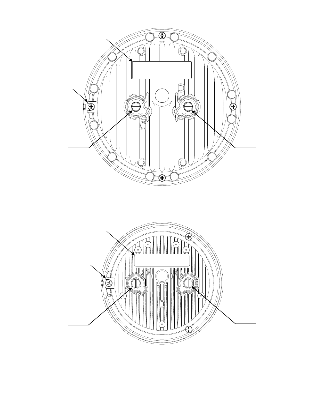
10. Secure the LED Light, note the terminal markings for
positive and negative, attach the negative marked wire
to the negative side terminal post of the LED Light.
11. Attach the positive wire to the positive side terminal
post. Remove tape or temporary placard which
identified the polarity of the wiring inside the housing.
12. If required, install the rubber gasket included with your
new LED Light around the LED Light assembly. A light
application of a common hand soap on the rubber may
aid in its fit into the light housing.
13. Place the LED light into the housing ensuring the key
(of the assembly) matches the key of the housing.
Proper orientation of the lamp is necessary for beam
orientation to be left and right of centerline while in
operation. For a Taxi light, the ‘lines’ of the inner optic
should be orientated vertically to produce a horizontal
light beam.
14. Secure the retainer. Care should be taken to tighten the
screw only to the point the retainer does not turn with
hand pressure. Over-tightening may stress the
polycarbonate lens of the LED Light.
15. Place the light switch in the ON position and verify
proper operation of the WAT LED lamp.
16. Determine that the Landing or Taxi light characteristics
have not been substantially affected, per 14CFR
23.1383.
17. If required, update aircraft records utilizing FAA Field
Approval (Form 337) or equivalent.
*NOMINAL

Page 2
PAR46
(reference-only)
PAR36
(reference-only)
GND
Polarity shown
on label
+VDC
www. .comflyWAT
+14V
+14V
GND
www. .comflyWAT
Polarity shown
on label
Alignment
Key
Alignment
Key
GROUND
Note - The ground
terminal is electrically
isolated from the case.
GROUND
Note - The ground
terminal is electrically
isolated from the case.
+VDC

Page 3
AIRWORTHINESS LIMITATIONS: The Airworthiness Limitations section is FAA approved and specifies inspections and other maintenance
required under §43.16 and §91.403 of the Federal Aviation Regulations, unless an alternative program has been approved. No airworthiness
limitations are associated with the installation of the light assembly.
No airworthiness limitations are associated with the installation of the LED Taxi and Landing Lights.
PERIODIC INSPECTIONS:
INTERVAL DESCRIPTION ACTIONS NOTES
Annually
(unless the OEM
specifies a shorter
interval)
• Perform function check.
Observe that all LEDs are
illuminated.
Note: To reduce eye strain
during LED inspection,
use an optical filter such
as dark glasses or a blue
covering dome.
• Inspect lens for abrasion,
crazing or cracking.
For additional lens
maintenance detail see SAE
ARP5637.
• Check Mounting,
connections and wire
integrity.
• Replace if all LEDs
are not illuminated.
• Replace the lens.
• Adjust or replace as
required.
• The unit is not repairable.

Page 4
+14VGND
Existing
Ground
Wire Existing
Landing/Taxi Light
Switch
Existing
Aircraft
(+) VDC
Existing
Fuse or
Circuit Breaker
www. .com
flyWAT
TROUBLESHOOTING PROCEDURE: The following information is to provide guidelines for troubleshooting the LED Light
Models listed on page 1.
Note: A circuit feature of the Parmetheus Plus is multiple parallel paths of LEDs and fixed current sources. For this
reason, a group of 3 or 6 LEDs may not be illuminated, while the remainder of the LEDs may be operating at full intensity.
This creates a situation where the light may be producing adequate light to perform its intended function, but it should still
be replaced.
In the case of no light output:
1. For a new installation, check the polarity of the wire connections. Check that the appropriate part has been
selected for the aircraft.
2. Check for the correct voltage at the light (+14V / 28V) terminal. Check for ground at the (GND) terminal.
3. Check the connections at the (+14V / 28V) and (GND) terminals.
4. Perform a bench check and replace if a failure is confirmed.
Refer to the aircraft manual for additional information.
Wiring Diagram

Page 5
Lens Replacement Procedure:
Note: The procedure outlined herein is common to the PAR36 and PAR46 models.
1. Remove the PAR36/PAR46 light assembly from its installed location
2. Remove the phillips-head screws (Item 2) used to secure the lens to the light assembly. Note that there are
4 screws used for this in the PAR46 and 3 in the PAR36.
3. Separate and remove the existing lens from the light assembly.
4. Install the replacement lens (Item 1) onto the light assembly, making sure that the lens’ alignment tab
engages the assembly’s alignment slot.
5. Secure the replacement lens to the light assembly using the existing hardware. Care should be taken not to
over-tighten these screws. Over-tightening may stress the lens.
2
3
2
1
ITEM PART NUMBER DESCRIPTION
REPLACEMENT PARTS:
PAR36 (All Models)
LENS, CLEAR NON OPTIC PAR-36
SCREW, 4 X 3/8 PFH PLASTI-LOC SS W/NYSEAL
SCREW, 8-32 X 1/4 PH SLOT, BRASS, TERMINAL (NOT SHOWN)
GASKET, PAR36, BLK (NOT SHOWN)
68-3971486A30
15-045216-068
14-082202-041
38-0240197-00
QTY
4
3
11
2
3
2
1
ITEM PART NUMBER DESCRIPTION
REPLACEMENT PARTS:
PAR46 (All Models)
LENS, CLEAR NON OPTIC PAR-46 LED
SCREW, 4 X 3/8 PFH PLASTI-LOC SS W/NYSEAL
SCREW, 8-32 X 1/4 PH SLOT, BRASS, TERMINAL (NOT SHOWN)
GASKET, PAR46, BLK (NOT SHOWN)
68-3971577A30
15-045216-068
14-082202-041
38-0240063-00
QTY
4
4
11
1
1
Alignment Tab
Alignment Slot
2
2
Alignment Tab
Alignment Slot
This manual suits for next models
11
Table of contents
Other Whelen Engineering Company GPS manuals