Whirlpool ACO D 103 User manual

8720030/WP
IT ABBATTITORI
ISTRUZIONI PER L’INSTALLAZIONE, L’USO E LA MANUTENZIONE
EN BLAST CHILLERS
INSTRUCTIONS FOR THE INSTALLATION, USE AND MAINTENANCE
DE SCHNELLKÜHLER
ANLEITUNGEN FÜR DEN INSTALLATEUR, BEDIENUNGS-UND WARTUNG
FR CELLULES DE REFROIDISSEMENT
INSTRUCTIONS POUR L’INSTALLATION, L’EMPLOI ET LA MAINTENANCE
ES
ABATIDORES
INSTRUCCIONES PARA LA INSTALACIÓN, USO Y MANTENIMIENTO
NL
SNELKOELERS
INSTALLATIE-, GEBRUIKS- EN ONDERHOUDSINSTRUCTIES
ACO D 103
ACO D 205
ACO D 210

2

Dimensioni
Capacità
Distanza teglie
Peso a vuoto
Dimensions
Capacity
Trays distance
Empty weight
Abmessungen
Kapazität
Einschubabstand
Leergewicht
Dimensions
Capacité
Ecartement grilles
Poids à vide
Dimensiones
Capacidad
Distancia bandejas
Peso en vacío
Afmetingen
Capaciteit
Afstand dienbladen
Leeggewicht
mm 620 x 650 x h 670
3 x 1/1 GN
67 mm
54 kg
3

Dimensioni
Capacità
Distanza teglie
Peso a vuoto
Dimensions
Capacity
Trays distance
Empty weight
Abmessungen
Kapazität
Einschubabstand
Leergewicht
Dimensions
Capacité
Ecartement grilles
Poids à vide
Dimensiones
Capacidad
Distancia bandejas
Peso en vacío
Afmetingen
Capaciteit
Afstand dienbladen
Leeggewicht
mm 790 x 730 x h 880
5 x 1/1 GN - 60x40
67 mm
74 kg
4

Dimensioni
Capacità
Distanza teglie
Peso a vuoto
Dimensions
Capacity
Trays distance
Empty weight
Abmessungen
Kapazität
Einschubabstand
Leergewicht
Dimensions
Capacité
Ecartement grilles
Poids à vide
Dimensiones
Capacidad
Distancia bandejas
Peso en vacío
Afmetingen
Capaciteit
Afstand dienbladen
Leeggewicht
mm 790 x 830 x h 1450
10 x 1/1 GN
67 mm
118 kg
5

IT
Paragrafo
Pagina
Premessa
7
Dichiarazione di conformita’
7
Direttiva Europea 2012/19/UE
7
1.
Avvertenze
7
1.1
Avvertenze generali
7
1.2
Avvertenze tecniche
7
1.3
Avvertenze d’utilizzo
7
2.
Caratteristiche tecniche
8
2.1
Dati tecnici
8
3.
Avvertenze per l’installatore
8
3.1
Consegna del abbattitore
8
3.2
Movimentazione e posizionamento
8
3.3
Smaltimento dell’imballo
9
3.4
Dismissione e rottamazione dell’apparecchiatura
9
4.
Messa in funzione
9
5.
Pannello di controllo e legenda
10
5.1
Descrizione led parte inferiore display
10
6.
Funzionamento
10
6.1
Accensione e spegnimento
10
6.2
Blocco/sblocco della tastiera
10
6.3
Cicli di funzionamento
10
6.3A
Abbattimento e conservazione
11
6.3B
Abbattimento hard e conservazione
11
6.3C
Surgelazione e conservazione
11
6.3D
Surgelazione soft e conservazione
12
6.3E
Preraffreddamento
12
7.
Allarmi ed errori
13
7.1
Allarmi
13
7.2
Errori
13
8.
Pulizia e manutenzione
13
6

IT
PREMESSA
Il contenuto del presente manuale è riferito a diversi modelli di abbattitori, per questo motivo, non tutte le
funzionalità descritte potrebbero essere incluse nell’abbattitore da voi acquistato.
Il Costruttore declina ogni responsabilità per le possibili inesattezze contenute nel presente opuscolo, imputabili ad
errori di stampa o di trascrizione. Si riserva il diritto di apportare ai propri prodotti quelle modifiche che ritiene
necessarie o utili, senza pregiudicare le caratteristiche essenziali.
Questa apparecchiatura dovrà essere destinata solo all’uso per il quale è stata espressamente progettata e costru-
ita.
DICHIARAZIONE DI CONFORMITA’
Il Costruttore dichiara che gli apparecchi sono conformi alle prescrizioni CEE.
L’installazione dovrà essere effettuata in osservanza alle norme vigenti, soprattutto in merito all’areazione dei locali e
dei sistemi per l’evacuazione dei gas combusti.
N.B.: Il Costruttore declina ogni responsabilità in caso di danni diretti derivati da: uso non corretto, errata
installazione e da cattiva manutenzione.
DIRETTIVA EUROPEA 2012/19/UE
Questo apparecchio è contrassegnato in conformità alla Direttiva Europea 2012/19/UE, Waste Electrical and
Electronic Equipment (WEEE). Assicurandosi che questo prodotto sia smaltito in modo corretto, l’utente contribui-
sce a prevenire le potenziali conseguenze negative per l’ambiente e la salute.
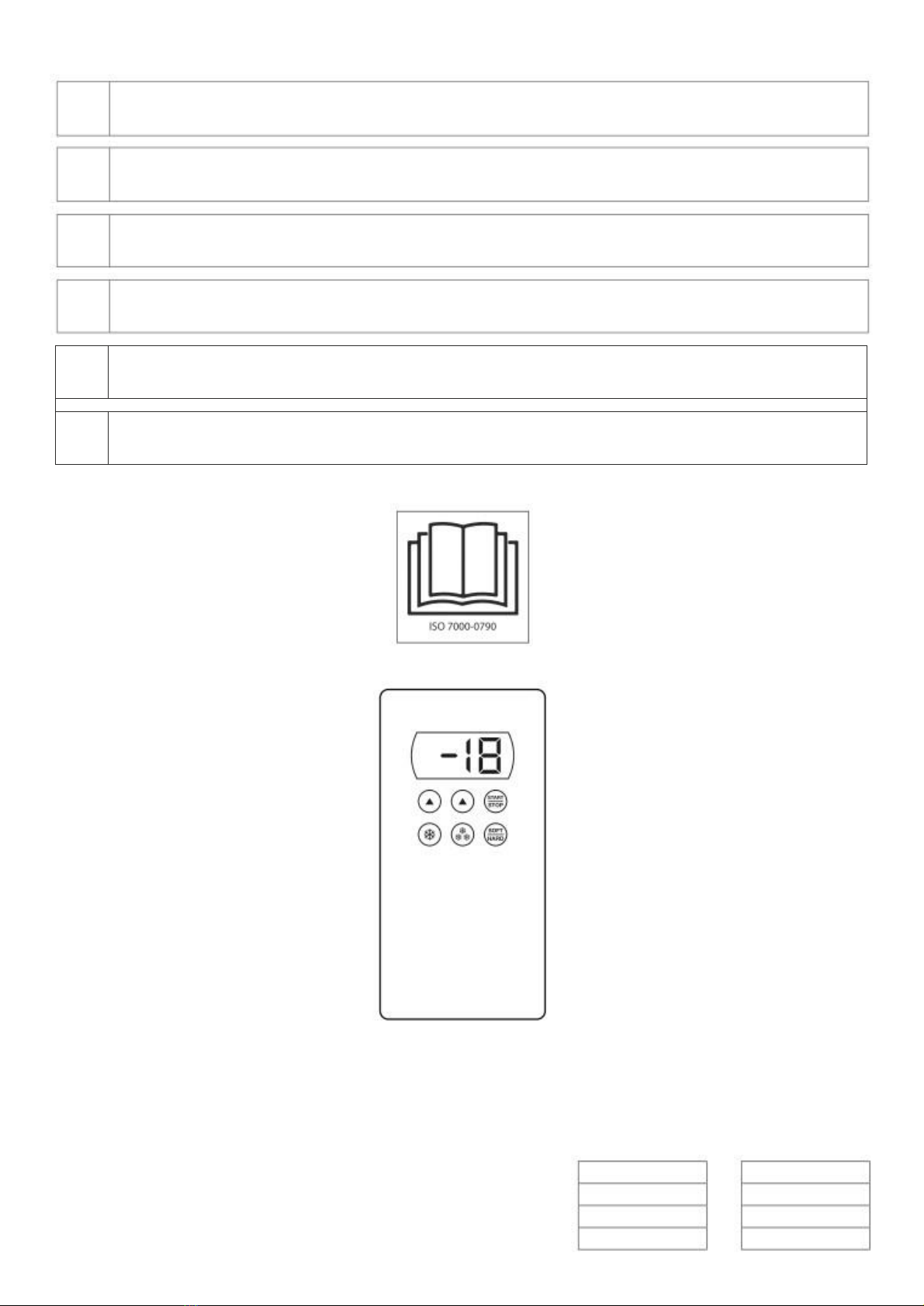
Il simbolo sul prodotto o sulla documentazione di accompagnamento indica che questo prodotto non
deve essere trattato come rifiuto domestico ma deve essere consegnato presso l’idoneo punto di
raccolta per il riciclaggio di apparecchiature elettriche ed elettroniche.
Disfarsene seguendo le normative locali per lo smaltimento dei rifiuti.
Per ulteriori informazioni sul trattamento, recupero e riciclaggio di questo prodotto, contattare l’i-
doneo ufficio locale, il servizio di raccolta dei rifiuti domestici o il negozio presso il quale il prodotto è
stato acquistato.
1. AVVERTENZE
1.1. AVVERTENZE GENERALI
Il presente manuale è stato realizzato per permettere una corretta installazione, messa a punto e manutenzione
dell’apparecchiatura.
E’ di fondamentale importanza che le avvertenze contenute nel presente libretto siano lette attentamente in quan-
to forniscono importanti indicazioni circa la sicurezza d’ installazione, d’uso e di manutenzione. Il presente manuale
e lo schema elettrico devono essere conservati con cura e messi a disposizione dell’operatore per ogni ulteriore
consultazione. L’apparecchiatura deve essere installata, collaudata ed assistita da personale qualificato in posses-
so dei requisiti di legge. L’apparecchiatura è stata progettata e realizzata per l’abbattimento e la conservazione
di prodotti alimentari e dovrà pertanto essere destinata solo all’uso per il quale è stata espressamente concepita.
Qualsiasi impiego diverso da quello specificato non comporta per il costruttore impegno o vincolo d’alcun genere.
Viene declinata ogni responsabilità del produttore con decadimento della garanzia in caso di modifiche elettriche
e/o meccaniche.
Manomissioni in genere non espressamente autorizzate e che non rispettino quanto riportato nel presente ma-
nuale, fanno decadere la garanzia. Disattivare l’apparecchiatura in caso di guasto o di cattivo funzionamento. Per
l’eventuale riparazione rivolgersi esclusivamente ad un centro di assistenza tecnica autorizzato dal costruttore e
richiedere l’utilizzo di ricambi originali. In caso di dubbio non utilizzare l’apparecchiatura e rivolgersi a personale
professionalmente qualificato. Il mancato rispetto di quanto sopra può compromettere la sicurezza dell’apparec-
chiatura. Osservare le norme di sicurezza locali vigenti al momento dell’installazione. Verificare che le caratteristi-
che della rete elettrica siano conformi ai dati riportati sulla targhetta matricolare.
Il materiale di imballaggio (sacchetti in plastica, polistirolo espanso, chiodi, ecc.) in quanto potenziale fonte di peri-
colo deve essere tenuto fuori dalla portata dei bambini e correttamente riciclato secondo le norme locali in vigore.
1.2. AVVERTENZE TECNICHE
L’apparecchiatura deve essere adoperata solo da personale adeguatamente formato.
Tenere lontani i bambini dall’apparecchiatura, soprattutto se in funzione.
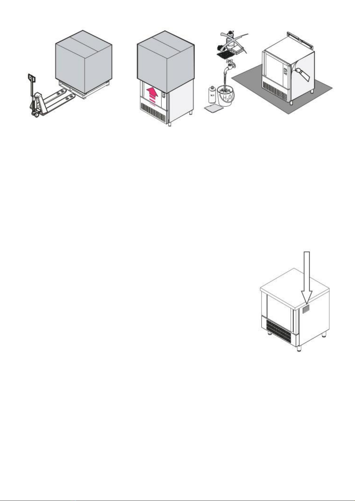
Ogni apparecchiatura è dotata di una targhetta caratteristiche che ne identifica il modello e i dati tecnici principali.
1.3. AVVERTENZE D’UTILIZZO
In fase di primo utilizzo, fare attenzione che nella cella dell’apparecchiatura non vi siano materiali estranei (libretto
istruzioni, sacchetti di plastica etc.).
Non mettere in trazione il cavo di alimentazione prima di adoperare l’abbattitore per la prima volta, pulire accura-
tamente la cella utilizzando prodotti non corrosivi (alcalini) per non danneggiare le superfici.
Evitare di utilizzare materiali e prodotti abrasivi per non graffiare le superfici. Durante il funzionamento dell’appa-
recchiatura non ostruire le prese d’aria per non comprometterne il buon funzionamento.
7

IT
Alla fine dell’utilizzo quotidiano pulire l’interno della cella e l’esterno dell’apparecchiatura: questo prolungherà la
sua durata e ne assicurerà il buon funzionamento. Non utilizzare getti d’acqua in pressione per la pulizia dell’ab-
battitore. In caso di dismissione dell’apparecchiatura interrompere e scollegare la linea di alimentazione elettrica.
2. CARATTERISTICHE TECNICHE
2.1. DATI TECNICI
Modello
Capacitá refrigerante
Tensione
Gas
Pot. refrig.
Pot. tot.
Vol. imballo
Peso lordo
3 x 1/1GN
8 Kg (+3 °C)
5 Kg (-18 °C)
230 V
1N 50 Hz
R452A
0.46 Kw
0.5 Kw
0.37 m3
64 kg
5 x 1/1 GN
+ 60x40
12 Kg (+3 °C)
8 Kg (-18 °C)
230 V
1N 50 Hz
R452A
0.65 Kw
0.65 Kw
0.68 m3
86 kg
10 x 1/1 GN
+ 60x40
25 Kg (+3 °C)
15 Kg (-18 °C)
230 V
1N 50 Hz
R452A
1.17 kW
1.21 kW
1.19 m3
118 kg
3. AVVERTENZE PER L’INSTALLATORE
Leggere attentamente le istruzioni contenute in questo libretto , perché esse forniscono importanti indicazioni
riguardo la sicurezza dell’installazione e l’uso dell’abbattitore.
3.1. CONSEGNA DEL ABBATTITORE
L’apparecchiatura arriva protetta da un imballo. Controllare all’arrivo che l’apparecchiatura non abbia subito
danneggiamenti durante il trasporto e che la stessa sia completa nelle sue parti come da ordine. Verificare che le
caratteristiche della rete elettrica siano conformi ai dati riportati sulla targhetta matricolare. Osservare le norme di
sicurezza locali vigenti al momento dell’installazione.
Nel caso di danni visibili annotare immediatamente sul documento relativo al trasporto il danno riscontrato ripor-
tando la dicitura : “RITIRO CON RISERVA PER EVIDENTI DANNI AD IMBALLO”.
3.2. MOVIMENTAZIONE E POSIZIONAMENTO
IMPORTANTE: tutte le operazioni di seguito citate debbono essere eseguite in conformità’ alle norme di sicurez-
za vigenti, sia per quanto relativo all’attrezzatura usata sia per quanto relativo alle modalità operative.
ATTENZIONE: prima di dar corso ad operazioni di movimentazione assicurarsi che la capacita’ di sollevamento (del
carrello elevatore o similare) sia adeguata al peso dell’apparecchiatura in questione.
Movimentare l’apparecchiatura con carrello elevatore o similare (fig. A): inserire le forche sul lato anteriore o po-
steriore della pedana di legno a corredo dell’apparecchiatura. Dar corso al sollevamento assicurandosi che l’appa-
recchiatura sia in equilibrio stabile.
ATTENZIONE: nel corso della movimentazione non capovolgere o rovesciare.
AVVERTENZE: il rispetto delle raccomandazioni riportate sul lato esterno dell’imballo è garanzia di integrità fisica e
funzionale dell’apparecchiatura a tutto vantaggio dell’utilizzatore finale.
SI RACCOMANDA QUINDI DI:
• MOVIMENTARE CON CURA
• TENERE ALL’ASCIUTTO
• EVITARE NEL MODO PIÙ ASSOLUTO DI SOVRAPPORRE ALTRI OGGETTI ALL’APPARECCHIATURA
• NON COMPRIMERE LATERALMENTE
• NON CAPOVOLGERE
• LEGGERE SUL CARTONE D’IMBALLO SE E’ POSSIBILE IMPILARE PIÙ ABBATTITORI DELLO STESSO MODELLO ED IL
NUMERO MASSIMO DI PEZZI CHE SI POSSONO IMPILARE.
Movimentare l’apparecchiatura con carrello elevatore e collocarla nel luogo scelto (fig. A).
Togliere l’imballo (fig. B); togliere manualmente la pellicola di protezione sulle parti in acciaio, evitando di utilizzare
sostanze abrasive e/o oggetti metallici (fig. C).
Collocare l’apparecchiatura assicurandosi che essa sia perfettamente in piano (fig. C), altrimenti agire sui piedini ad
altezza regolabile affinché essa sia posizionata in maniera corretta.
Collocare l’apparecchiatura lontano da fonti di calore e ad una distanza adeguata da muri o altre apparecchiature in
modo tale da permettere circolazione d’aria soprattutto nella zona anteriore e posteriore.
Evitare di ammassare oggetti in corrispondenza delle prese d’aria dell’apparecchiatura.
Cercare di collocare l’apparecchiatura in modo che qualsiasi operazione di installazione, manutenzione ordinaria e
straordinaria, nonché interventi di riparazione, siano facilmente effettuabili e per permet-
tere un’adeguata circolazione d’aria.
8

IT
C
AB
3.3. SMALTIMENTO DELL’IMBALLO
Togliere le protezioni e l’imballo; sollevare l’apparecchiatura in modo da separarla dalla pedana; appoggiare l’ap-
parecchiatura a terra in corrispondenza del punto predestinato; verificare la presenza di danni visibili; tenere fuori
dalla portata dei bambini il materiale di imballo in quanto potenziale fonte di pericolo; smaltire i prodotti di imballo
facendoli confluire ai centri di raccolta o di riciclaggio specializzati attenendosi alle norme vigenti.
3.4. DISMISSIONE E ROTTAMAZIONE DELL’APPARECCHIATURA
Nel caso di dismissione, prima di rottamare l’apparecchiatura è doveroso renderla inoperante togliendo il cavo d’a-
limentazione, eliminando quelle parti che possono costituire un pericolo e rendendo inservibili serratura, cerniera
od altri sistemi.
IMPORTANTE: RISPETTARE LE NORMATIVE LOCALI PER LA ROTTAMAZIONE DI QUESTO GENERE DI APPAREC-
CHIATURE.
4. MESSA IN FUNZIONE
Prima di collegare l’apparecchiatura accertarsi che i dati di targa siano rispondenti a
quelli della rete elettrica.
La targhetta matricolare recante i dati elettrici necessari all’installazione è posta sul
fianco destro dell’apparecchiatura in alto.
L’installazione deve essere effettuata secondo le istruzioni riportate alla presente se-
zione da personale professionalmente qualificato.
LA SICUREZZA ELETTRICA DI QUESTA APPARECCHIATURA È ASSICURATA SOLTANTO
QUANDO LA STESSA È CORRETTAMENTE COLLEGATA AD UN EFFICACE IMPIANTO DI
MESSA A TERRA COME PREVISTO DALLE VIGENTI NORME DI SICUREZZA ELETTRICA.
È NECESSARIO VERIFICARE QUESTO FONDAMENTALE REQUISITO DI SICUREZZA E, IN
CASO DI DUBBIO, RICHIEDERE UN CONTROLLO ACCURATO DELL’IMPIANTO DA
PARTE DI PERSONALE PROFESSIONALMENTE QUALIFICATO.
IL COSTRUTTORE DECLINA OGNI RESPONSABILITÀ’ PER EVENTUALI DANNI CAUSATI DALLA MANCAN-
ZA DI MESSA A TERRA DELL’IMPIANTO.
Controllare che l’apparecchiatura sia stata posta in bolla.
Agire eventualmente sulla parte mobile dei piedini regolabili fino ad ottenere un perfetto allineamento.
Controllare che sia stata tolta la plastica a protezione delle superfici esterne.
Controllare che sia stato lavato all’interno con acqua tiepida e sapone neutro.
Controllare che sia stato posto il più lontano possibile da fonti di calore.
Controllare che non sia impedito il libero circolare dell’aria nel vano motore.
Controllare il valore della tensione e della frequenza di rete che devono rientrare nei valori riportati:
230 V ± 10% ; 50 Hz / 400 V ± 10% ; 50 Hz
9

IT
5. PANNELLO DI CONTROLLO
Tasto abbattimento
Tasto surgelazione
Tasto abbattimento hard o surgelazione soft
Tasto start/stop (accensione/spegnimento)
Tasto incremento
Tasto decremento
5.1 DESCRIZIONE LED PARTE INFERIORE DISPLAY
Nella parte inferiore del display ci sono dei led che forniscono importanti informazioni relative alla modalità di
funzionamento.
Indica che è in corso un ciclo di abbattimento
Indica che è in corso un ciclo di surgelazione
Indica che il ciclo in corso è con controllo di temperatura
Indica che il ciclo in corso è con controllo a tempo
Indica che è in corso un ciclo di abbattimento hard
Indica che è in corso una fase di conservazione
Indica che è in corso una fase di preraffreddamento
Indica che è in corso uno sbrinamento
Indica che la temperatura è visualizzata in gradi Celsius
Indica che la temperatura è visualizzata in gradi Fahrenheit
Indica che l’abbattitore è in stand-by
6. FUNZIONAMENTO
6.1 ACCENSIONE E SPEGNIMENTO
Per accendere o spegnere l’abbattitore, tenere premuto per 1 secondo il tasto start/stop.
Quando l’abbattitore è acceso, il display visualizza la temperatura all’interno della cella.
6.2 BLOCCO/SBLOCCO DELLA TASTIERA
Per bloccare o sbloccare la tastiera, procedere come segue.
Bloccare: tenere premuti i tasti decremento e start/stop per 1 secondo. Il display mostra Loc per 1 secondo. Quando
la tastiera è bloccata, non è consentita nessuna operazione.
Sbloccare: tenere premuti i tasti decremento e start/stop per 1 secondo. Il display mostra UnL per 1 secon-
do.
6.3 CICLI DI FUNZIONAMENTO
L’abbattitore è in grado di gestire i seguenti tipi di cicli di funzionamento:
• Abbattimento e conservazione
• Abbattimento hard e conservazione
• Surgelazione e conservazione
• Surgelazione soft e conservazione
10

IT
6.3A ABBATTIMENTO E CONSERVAZIONE
Il ciclo di abbattimento a temperatura e conservazione è suddiviso nelle seguenti fasi:
• abbattimento
• conservazione
Alla conclusione di una fase, l’abbattitore passa automaticamente alla successiva.
Per avviare il ciclo:
• Premere e rilasciare il tasto abbattimento (il led abbattimento ed il led sonda lampeggiano).
• Premere start, quando il sensore misura una temperatura identica alla camera (segnale sonoro e la sonda lam-
peggia), passa automaticamente a tempo.
• Selezionando l’abbattimento rapido a temperatura, il display mostra la temperatura misurata dalla sonda al
termine dell’abbattimento rapido.
• Selezionando l’abbattimento a temperatura, il display mostrerà la temperatura che la sonda rileverà a fine ab-
battimento.
• Selezionando l’abbattimento a tempo, invece, il display visualizzerà la durata del ciclo.
• Dopo aver selezionato il tipo di abbattimento (a temperatura o a tempo) è possibile modificare il valore di fine
ciclo premendo (entro 15 secondi) il tasto incremento o quello decremento fino a raggiungere il valore pre-
scelto.
• A questo punto, per avviare il ciclo premere e rilasciare il tasto start/stop.
• Se è stato selezionato l’abbattimento a temperatura, il sistema avvia un test per la verifica del corretto inseri-
mento della sonda. Se il test viene completato con successo il ciclo di raffreddamento verrà avviato; altrimenti
verrà avviato un ciclo di raffreddamento a tempo (in questo caso, si spegne il led sonda e si accende il led
tempo).
• Per interrompere il ciclo di raffreddamento, tenere premuto il tasto start/stop.
• Durante l’abbattimento a temperatura, è possibile visualizzare nel display la temperatura della cella premendo
il tasto abbattimento. Trascorsi 15 secondi, il display torna a visualizzare la temperatura rilevata dalla sonda.
• Se la temperatura rilevata dalla sonda raggiunge il valore di fine abbattimento entro la durata massima prevista, il
ciclo verrà considerato corretto e l’abbattitore passerà automaticamente alla fase di conservazione.
• Al passaggio dalla fase di abbattimento a quella di conservazione, si attiva il buzzer per un tempo prestabilito.
• Durante la conservazione il display visualizza la temperatura rilevata dalla sonda e nella parte bassa del display si
accende il led conservazione.
• Se la temperatura rilevata dalla sonda non raggiunge il valore di fine abbattimento entro la durata massima pre-
vista, l’abbattimento non verrà completato in modo corretto ma continuerà.
• Il led sonda lampeggerà e il buzzer verrà attivato.
6.3B ABBATTIMENTO HARD E CONSERVAZIONE
Il ciclo di abbattimento hard a temperatura e conservazione è suddiviso nelle seguenti fasi:
• abbattimento hard
• abbattimento
• conservazione
Alla conclusione di una fase, l’abbattitore passa automaticamente alla successiva.
Per avviare il ciclo:
• Premere e rilasciare il tasto abbattimento (il led abbattimento ed il led sonda lampeggiano).
• Premere e rilasciare il tasto hard/soft (il led hard lampeggia).
• A questo punto, per avviare il ciclo premere e rilasciare il tasto start/stop.
6.3C SURGELAZIONE E CONSERVAZIONE
Il ciclo di surgelazione e conservazione è suddiviso nelle seguenti fasi:
• surgelazione
• conservazione
Alla conclusione di una fase, l’abbattitore passa automaticamente alla successiva.
11

IT
Per avviare il ciclo:
• Premere e rilasciare il tasto surgelazione (i led abbattimento, surgelazione, hard e sonda lampeggiano).
• Premendo nuovamennte il tasto surgelazione si passa dalla surgelazione a temperatura a quella a tempo (in
questo caso, lampeggiano i led tempo e si spegne il led sonda).
• A questo punto, per avviare il ciclo premere e rilasciare il tasto start/stop.
• Il sistema avvia un test per la verifica del corretto inserimento della sonda. Se il test viene completato con suc-
cesso il ciclo di surgelazione verrà avviato.
6.3D SURGELAZIONE SOFT E CONSERVAZIONE
Il ciclo di surgelazione soft e conservazione è suddiviso nelle seguenti fasi:
• fase soft della surgelazione
• surgelazione
• conservazione
Alla conclusione di una fase, l’abbattitore passa automaticamente alla successiva.
Per avviare il ciclo:
• Premere e rilasciare il tasto surgelazione (i led abbattimento, surgelazione, hard e sonda lampeggiano).
• Premere e rilasciare il tasto hard/soft (il led hard si spegne).
• A questo punto, per avviare il ciclo premere e rilasciare il tasto start/stop.
• Il sistema avvia un test per la verifica del corretto inserimento della sonda. Se il test viene completato con suc-
cesso il ciclo di surgelazione verrà avviato.
6.3E PRERAFFREDDAMENTO
Ogni ciclo di raffreddamento può essere preceduto da un preraffreddamento.
Per avviare il preraffreddamento:
• Premere e tenere premuto per 1 secondo il tasto abbattimento (il led preraffreddamento lampeggerà).
• La fase di preraffreddamento inizierà e proseguirà fino a raggiungere la temperatura prevista per il preraffred-
damento.
• Quando la cella raggiunge la temperatrura prevista, il led preraffreddamento smette di lampeggiare e rimane
fisso.
• Il buzzer si attiva per un secondo.
• Il preraffreddamento prosegue fino a quando non viene avviato un ciclo. Per
interrompere il preraffreddamento:
• Premere e tenere premuto per 1 secondo il tasto abbattimento o avviare un ciclo.
12

IT
7 ALLARMI ED ERRORI
7.1 ALLARMI
La seguente tabella illustra il significato dei codici di allarme:
Codice
Descrizione
Cause
Ripristino
tiME
Ciclo di abbattimento o surgelazio-
ne a temperatura non completato
entro la durata massima prevista.
Automatico
id
Porta aperta
Chiusura porta non efficiente.
Possibile rottura del micro porta o
del sensore magnetico.
Automatico
HP
Alta pressione
Probabile eccessiva quantità di pro-
dotto per teglia.
Automatico
COH
Condensatore surriscaldato
Contattare Servizio Tecnico
CSd
Compressore bloccato
Contattare Servizio Tecnico
7.2 ERRORI
La seguente tabella illustra il significato dei codici di errore:
Codice
Descrizione
Cause e soluzione
Ripristino
Pr1
Errore sonda cella
Sonda scollegata o rotta.
Controllare integrità sonda.
Controllare connessione sonda - di-
spositivo. Sostituire sonda.
Automatico
Pr2
Errore sonda a spillone
Sonda scollegata o rotta.
Controllare integrità sonda.
Controllare connessione sonda - di-
spositivo. Sostituire sonda.
Automatico
Pr3
Errore sonda evaporatore
Contattare Servizio Tecnico
Pr4
Errore sonda condensatore
Contattare Servizio Tecnico
8. PULIZIA E MANUTENZIONE
Questa sezione è dedicata all’utilizzatore finale ed è estremamente importante per il regolare funzionamento nel
tempo dell’apparecchiatura. Poche operazioni eseguite con scrupolo e periodicamente possono evitare di dover
ricorrere ad interventi di personale specializzato.
Le operazioni da effettuare non richiedono conoscenze tecniche particolari e si riassumono in semplici controlli ai
componenti dell’apparecchiatura.
PRIMA DI DAR CORSO A QUALSIASI OPERAZIONE DI MANUTENZIONE O DI PULIZIA DELL’APPAREC-
CHIATURA DISINSERIRE LA STESSA DALLA RETE DI ALIMENTAZIONE ELETTRICA.
ATTENZIONE NON LAVARE L’APPARECCHIATURA CON GETTI D’ACQUA DIRETTI E AD ALTA PRESSIO-
NE. EVITARE DI INDIRIZZARE L’ACQUA SULLE PARTI ELETTRICHE.
ABBATTITORE Verificare lo stato di pulizia delle parti costituenti la struttura. Particolare attenzione va posta alle parti
di acciaio. Pulire le superfici interne ed esterne usando solo acqua e sapone o detergente neutro. Risciacqua-
re abbondantemente con acqua ed asciugare con cura. Se l’apparecchiatura rimane ferma a lungo inoperante si
raccomanda di spegnerla, staccare il cavo dalla presa di corrente elettrica. Pulire bene l‘apparecchiatura con acqua e
detergenti neutri o sapone neutro.
Asciugarla con cura e una volta ben asciutta stendere un velo d’olio di vaselina con un panno morbido. Lasciare
aperta la porta dell’abbattitore: in questo modo circolerà l’aria, non si formeranno condense o odori spiacevoli.
SONDA SPILLONE Dopo ogni utilizzo della sonda spillone si raccomanda di pulirla bene e, tra un utilizzo e l’altro, in fase
di stand-by, alloggiarla nell’apposito sito dopo averle messo il cappuccio in gomma.
CONDENSATORE Almeno una volta al mese verificare lo stato del condensatore e pulirlo dalla polvere:
Svitare le viti posizionate sotto il cruscotto, sfilare il cruscotto verso il basso ed appoggiarlo con cura in modo da non
rovinarlo, proteggersi le mani con guanti adeguati in quanto le alette del condensatore sono taglienti. Spazzo-
lare con una spazzola a setole morbide il condensatore o aspirare la polvere con un aspirapolvere munito di prolun-
ga e bocchettoni appositi. Non piegare le alette: attenzione a non urtarle con forza in quanto potrebbero piegarsi. E’
vietato pulire il condensatore con acqua, acidi o altri sistemi di pulitura se non indicati in questo libretto di istru-
zioni installazione, uso e manutenzione.
Verificare anche il pannello posto sul retro dell’apparecchiatura: potrebbero accumularsi sporcizia o altri materiali
che potrebbero sporcare l’unita’ moto condensante, pregiudicandone l’efficienza.
13

EN
Paragraph
Page
Foreword
15
Declaration of conformity
15
European directive ROHS 2012/19/UE
15
1.
Warnings
15
1.1
General warnings
15
1.2
Technical warnings
15
1.3
Use warnings
15
2.
General technical features
16
2.1
Data sheet
16
3.
Instructions for the installer
16
3.1
Controls at reception
16
3.2
Handling and placing
16
3.3
Unpacking and disposal of it
17
3.4
Disposal of unit
17
4.
Start-up
17
5.
Control panel
18
5.1
Description of the led in the lower side of the display
18
6.
Operation
18
6.1
Switching the device on/off
18
6.2
Locking/unlocking the keyboard
18
6.3
Operating cycles
18
6.3A
Blast chilling and conservation
19
6.3B
Hard blast chilling and conservation
19
6.3C
Deep freezing and conservation
19
6.3D
Soft deep freezing and conservation
20
6.3E
Pre-cooling
20
7.
Alarms and errors
21
7.1
Alarms
21
7.2
Errors
21
8.
Cleaning and maintenance
21
14

EN
FOREWORD
The contents of this manual are generic and not all the functions described may be available on your
product.
The manufacturer declines all responsibility for possible inaccuracies contained in this pamphlet, due to printing or
copy errors. We reserve the right to make on our own products those changes to be considered necessary or useful,
without jeopardizing the essential characteristics.
Read the instructions for use very carefully paying particular attention to the rules concerning safety devices.
This appliance must only be used for what it has been designed for and built for.
DECLARATION OF CONFORMITY
The Manufacturer declares that the appliances conform to the EEC norms.
They must be installed in accordance with current standards, especially regarding aeration of the premises and the
exhaust gas evacuation system.
Note: The Manufacturer declines all and every responsibility for any direct damages caused by: an in-
correct use, wrong installation or bad maintenance.
EUROPEAN DIRECTIVE ROHS 2012/19/UE
This appliance is marked according to the European directive 2012/19/UE on Waste Electrical and Electronic Equip-
ment (WEEE).
By ensuring this product is disposed correctly, you will help prevent potential negative consequences
for the environment and human health, which could otherwise be caused by inappropriate waste
handling of this product.
The symbol on the product, or on the documents accompanying the product, indicates that this ap-
pliance may not be treated as household waste.
Instead it shall be handed over to the applicable collection point for the recycling of electrical and
electronic equipment.
Disposal must be carried out in accordance with local environmental regulations for waste disposal.
1. WARNINGS
1.1. GENERAL WARNINGS
This manual has been prepared to enable a correct installation, regulation and maintenance of the appliance. It is
therefore of basic importance that the warnings contained in this booklet are carefully read as they supply essential
indications regarding the safety of the installation, use and maintenance.
This manual and the wiring diagram must be stored with care and made available to the operator for any future
consultation. The appliance must be installed, tested and serviced by qualified personnel in possession of the legal
qualifications. The constructor declines all responsibility with invalidity of the warranty in the event of electrical
and/or mechanical modifications.
Any adjustment whatsoever not expressly authorised and in disrespect of this manual invalidate the warranty.
Observe all existing local regulations at the time of installation. Check that the characteristics of the electric grid
correspond to the data given on the serial plate of the appliance. The packing materials (plastic bags, polystyrene,
nails, etc.) as potential hazards, must be kept out of the reach of children and properly recycled according to the
existing local regulations.
The appliance has been designed and constructed for the blast chilling and freezing of foodstuffs and should
therefore be destined to this sole purpose for which it has been expressly conceived. Any use besides this specific
purpose does not commit the constructor in any way. Shutdown the appliance in the event of breakdown or mal-
functions. For eventual repairs contact exclusively the authorised service centres and request the use of original
spare parts. If in doubt do not use the appliance and contact professionally qualified personnel. The disrespect of the
above conditions could risk the safety of the appliance.
1.2. TECHNICAL WARNINGS
The appliance must be used by qualified personnel. Keep off the children from the appliance above all if it is in
function. Every appliance has a serial plate on the right side.
1.3. USE WARNINGS
Remove from the room any stranger material as manual, plastic bags, polystyrene, nails, etc before start operating with
the equipment. Clean the inside and outside surfaces only with warm water and soap or a neutral detergent. Rinse
with plenty of water and dry thoroughly.
Don’t use abrasive brushes or other damaging materials for the appliance’s surfaces.
At the end of the working day, clean the inside (above all) and outside of the machine, to ensure smooth operation
of the appliance and prolong its useful life. Do not use high pressure water jets when cleaning the appliance.
15

EN
Never stretch the power cable. Place the machine in a ventilated room. When using the appliance, never obstruct the
air inlet when the appliance in on , so as not to compromise its performance and safety.
For the final disposal of this appliance, comply with local regulations in force.
2. GENERAL TECHNICAL FEATURES
2.1. DATA SHEET
Model
Cooling capacity
Voltage
Gas
Cooling pow.
Tot. pow.
Packed vol.
Gross Weight
3 x 1/1GN
8 Kg (+3 °C)
5 Kg (-18 °C)
230 V
1N 50 Hz
R452A
0.46 Kw
0.5 Kw
0.37 m3
64 kg
5 x 1/1 GN
+ 60x40
12 Kg (+3 °C)
8 Kg (-18 °C)
230 V
1N 50 Hz
R452A
0.65 Kw
0.65 Kw
0.68 m3
86 kg
10 x 1/1 GN
+ 60x40
25 Kg (+3 °C)
15 Kg (-18 °C)
230 V
1N 50 Hz
R452A
1.17 kW
1.21 kW
1.19 m3
118 kg
3. INSTRUCTIONS FOR THE INSTALLER
Read carefully all the instructions in this manual, because they give important suggestions about the right instal-
lation and use of the appliance.
3.1. CONTROLS AT RECEPTION
The appliance are shipped in appropriate protective packing.
On arrival, check that the appliance has not incurred in transport damage and that it is complete according to
the order.
In the event of visible damage immediately note the damage on the transport documents with the following
wording: “RECEIVED WITH RESERVE FOR EVIDENT DAMAGE OF PACKING”.
3.2. HANDLING AND PLACING
IMPORTANT: All the operations indicated below must be performed in respect of the existing safety regulations, both
for the equipment in use and for the operating procedures.
ATTENTION: Before beginning handling operations ensure that the lifting capacity is enough for the appliance in
question.
Handling with fork lift or similar (A); Insert the forks into the side or back of the wooden pallet supplied with the
appliance, begin lifting checking that the appliance is in stable equilibrium.
When insert the lifting device, pay attention to the power supply cable and the position of the feet.
ATTENTION: during handling do not tip or turn over.
WARNING: the respect of the recommendations printed on the outside of the packing is a guarantee of a sound
physical and operating condition of the appliance, all to the advantage of the end-user.
THEREFORE THE FOLLOWING IS RECOMMENDED:
• HANDLE WITH CARE
• KEEP DRY
• STACKING OF OTHER OBJECTS ON THE APPLIANCE MUST BE ABSOLUTELY AVOIDED
• DO NOT COMPRESS SIDEWAYS
• DO NOT TURN UPSIDE DOWN
• STACKING OF BLAST CHILLERS IS PERMITTED: READ CAREFULLY THE MAXIMUM PIECES’ NUMBER INDICATED ON
THE EMBALLAGE.
Lift the appliance to separate it from the pallet.
Remove the packing (B) and the protective film avoid using abrasive brushes or other damaging materials for the
appliance’s surfaces (C).
Check that the appliance is perfectly levelled.
Regulate the adjustable feet if necessary. Place the appliance away from heat sources and in a ventilated room.
When using the appliance, never obstruct the air inlet when the appliance in on, so as not to compromise its
performance and safety.
Placing the appliance in a site easy to join, so every type of maintenance, control and repair may be done easily.
16

EN
C
AB
3.3. UNPACKING AND DISPOSAL OF IT
Place the appliance on the ground in its chosen position.
Check that the serial number corresponds to the transport documents. Check for visible damages.
Keep the packing out of the reach of children, as it could be a danger hazard. Discharge the packing products to the
specialised collection or recycling points in respect of the existing regulations.
3.4. DISPOSAL OF UNIT
Before scrapping the appliance, keep it inoperative by removing the power cable, eliminating all parts of the
appliance that could constitute an hazard and invalidate locks, hinges and any other closing devices to avoid that
children playing could be trapped inside or injured.
IMPORTANT: COMPLY WITH LOCAL REGULATIONS IN FORCE CONCERNING THE FINAL DISPOSAL OF THIS TYPE OF
EQUIPMENT
4. START-UP
Before connecting the appliance check that the data on the serial plate correspond to
the actual electrical supply.
The serial plate giving the electrical data required in the installation is placed in the
right side.
The installation must be made according to the instructions given in this section, by
professionally qualified personnel.
THE ELECTRICAL SAFETY OF THIS APPLIANCE IS GUARANTEED ONLY WHEN IT IS
CONNECTED TO AN EFFICIENT EARTHING PLANT AS PRESCRIBED BY EXISTING
ELECTRICAL SAFETY REGULATIONS.
THIS BASIC SAFETY REQUIREMENT MUST BE VERIFIED AND, IF IN DOUBT, RE-
QUEST A CAREFUL CONTROL OF THE PLANT BY PROFESSIONALLY QUALIFIED PER-
SONNEL.
THE CONSTRUCTOR DECLINES ALL RESPONSIBILITY FOR DAMAGES CAUSED BY THE DISRESPECT OF AN
EFFICIENT EARTHING OF THE PLANT.
Check that the appliance is perfectly levelled.
Regulate the adjustable feet if necessary.
Check that the plastic protective coating is removed from all external surfaces.
Check that the interior is washed with warm water and a neutral soap.
Check that the appliance is positioned as far as possible from heat sources.
Check that the free air circulation around the motor compartment is not obstructed.
Control the voltage and frequency of the mains distribution, they must fall within the given values: 230 V ± 10%
; 50 Hz / 400 V ± 10% ; 50 Hz
17

EN
5. CONTROL PANEL
Blast chilling key
Deep freezing key
Hard blast chilling or Soft deep freezing key
Start/stop (on/off) key
Increase value key
Decrease value key
5.1 DESCRIPTION OF THE LED IN THE LOWER SIDE OF THE DISPLAY
In the lower part of the display there are LEDs that provide important information about the operating mode.
Indicates that a blast chilling cycle is in progress
Indicates that a deep freezing cycle is in progress
Indicates that the current cycle is with temperature control
Indicates that the current cycle is controlled by time
Indicates that a hard blast chilling cycle is in progress
Indicates that a conservation phase is in progress
Indicates that a pre-cooling phase is in progress
Indicates that a defrost is in progress
Indicates that the temperature is displayed in Celsius degrees
Indicates that the temperature is displayed in Fahrenheit degrees
Indicates that the blast chiller is in stand-by
6. OPERATION
6.1 SWITCHING THE DEVICE ON/OFF
Operate as follows: hold the START/STOP key down for 1 s.
When the blast chiller is on, the display shows the temperature inside the cell.
6.2 LOCKING/UNLOCKING THE KEYBOARD
To lock or unlock the keyboard operate as follows:
To lock: hold the down key and the start/stop key down for 1 s: the display will show Loc for 1 s. When
the keyboard is locked, no operation is allowed.
To unlock: hold the down key and the start/stop key down for 1 s: the display will show UnL for 1 s.
6.3 OPERATING CYCLES
The devices can manage the following operating cycles:
• Blast chilling and conservation
• Hard blast chilling and conservation
• Deep freezing and conservation
• Soft deep freezing and conservation.
18

EN
6.3A BLAST CHILLING AND CONSERVATION
The temperature-controlled blast chilling and conservation cycle is divided into the following two phases:
• Blast chilling
• Conservation
On conclusion of a phase, the device passes automatically to the next.
Operate as indicated to start the cycle:
• Press and release the blast chilling key: the blast chilling LED and the core probe LED will flash.
• Press start, when the sensor measures a temperature identical to the camera (sound signal and the probe flash-
es), it automatically switches to time.
• Selecting the temperature control, the display will show the temperature that the probe will detect at the end of
blast chilling.
• By selecting the time control, the display will show the duration of the cycle.
• After selecting the type of blast chilling (temperature or time control) it is possible to modify the end cycle value by
pressing (within 15 seconds) the key increase or the key decrease until reaching the chosen value.
• At this point, to start the cycle press and release the start/stop key.
• If the temperature control has been selected, the system starts a test to verify the correct insertion of the probe. If
the test is successfully completed the cooling cycle will start; otherwise a time-controlled cooling cycle will be started
(in this case, the probe led turns off and the time led lights up).
• To stop the cooling cycle, keep pressed the start/stop key.
• During temperature-controlled chilling, the cell temperature can be displayed by pressing the blast chilling key. After
15 seconds, the display returns to displaying the temperature detected by the probe.
• If the temperature detected by the probe reaches the blast chilling end value within the maximum expected du-
ration, the cycle will be considered correct and the blast chiller will automatically go to the conservation phase.
• When switching from blast chilling to conservation phase, the buzzer is activated for a set time.
• During storage, the display shows the temperature detected by the probe and the LED conservation lights up in the
lower part of the display.
• If the temperature detected by the probe does not reach the blast chilling end value within the maximum expect-
ed duration, blast chilling will not be completed correctly but will continue.
• The probe LED will flash and the buzzer will be activated.
6.3B HARD BLAST CHILLING AND CONSERVATION
The temperature-controlled hard blast chilling and conservation cycle is divided into the following three phases:
• blast chilling hard phase
• blast chilling
• conservation
On conclusion of a phase, the device passes automatically to the next.
Operate as indicated to start the cycle:
• Press and release the blast chilling key: the blast chilling LED and the core probe LED will flash.
• Press and release the hard/soft key (the hard LED will flash).
• At this point, to start the cycle press and release the start/stop key.
6.3C DEEP FREEZING AND CONSERVATION
The temperature-controlled deep freezing and conservation cycle is divided into the following two phases:
• Deep freezing
• Conservation
On conclusion of a phase, the device passes automatically to the next.
19

EN
Operate as indicated to start the cycle:
• Press and release the deep freezing key (the LED blast chilling, deep freezing, hard and probe will flash).
• Pressing again the deep freezing key the system passes from the temperature control to the time control (in this
case, the probe led turns off and the time led lights up).
• At this point, to start the cycle press and release the start/stop key.
• The system starts a test to verify the correct insertion of the probe. If the test is successfully completed the
cooling cycle will start.
6.3D SOFT DEEP FREEZING AND CONSERVATION
The soft deep freezing and conservation cycle is divided into the following two phases:
• Deep freezing soft phase
• Deep freezing
• Conservation
On conclusion of a phase, the device passes automatically to the next.
Operate as indicated to start the cycle:
• Press and release the deep freezing key (the LED blast chilling, deep freezing, hard and probe will flash).
• Press and release the hard/soft key (the hard led turns off).
• At this point, to start the cycle press and release the start/stop key.
• The system starts a test to verify the correct insertion of the probe. If the test is successfully completed the
cooling cycle will start.
6.3E PRE-COOLING
Each cooling cycle can be preceded by a precooling phase.
Operate as indicated to start pre-cooling:
• Hold the blast chilling key down for 1 second: (the pre-cooling LED will flash).
• The pre-cooling phase will start and continue until the temperature for pre-cooling is reached.
• When the cell reaches the expected temperature, the pre-cooling led stops flashing and remains fixed.
• The buzzer is activated for one second.
• Pre-cooling continues until a cycle is started. To
stop pre-cooling:
• Hold the blast chilling key down for 1 second or start a cycle.
20
This manual suits for next models
2
Table of contents
Languages:
Popular Chiller manuals by other brands

S&A
S&A CWUL-05 user manual

Norcool
Norcool Cu-350 user manual

Liebert
Liebert Process Fluid Chiller PS024A Specification sheet

Swegon
Swegon BlueBox Zeta Rev Series Installation, use and maintenance manual

hailea
hailea HC-100A instruction manual

Clint
Clint CHA 182-P-604-P INSTALLATION, USE AND MANTEINANCE MANUAL

Carrier
Carrier Pro-Dialog Plus 30SZ Installation, operation and maintenance instructions

Sterlco
Sterlco Sterlco Series R RTAA-110 Installation and maintenance manual

York
York YCAV0569 Installation operation & maintenance

AERMEC
AERMEC NRB 0800-3600 Technical manual

xtra
xtra XR10 Original service manual

AERMEC
AERMEC NBW 147 Technical and Installation Booklet