Whirlwind 216 User manual


STANDARD
EQUIPMENT
:
•
10
HP Baldor TEFC Motor
208
/
230
/
460
/ 3/
60
• 3 Premium V-Belts
• Filter, Regulator, Coalescing Filter w. Gauge
• Magnetic Starter
In
Nema
12
Box
with Low
Vo
ltage Controls
• Tempered Chrome-
Maly
Spindle
• Heavy Steel Spindle Housing
• 4" Cast Aluminum Dust Chute
•
Air
Supply Lock-Out
OPTIONAL
EQUIPMENT:
• 20"
A.TB
. or T.C.G. Systi-Matic Blades
• Spray
Mist
for Metal and Plastic Use
• Electric Delete Credit
• 15 HP Baldor TEFC Motor
• 7 1/ 2 HP Single Phase Motor
ELECTRICAL (Amps)
Current
230
Vo
lt
s
Motor Running
26
Amps
Service Current
50
Amps
460
Volts
13
Amps
25
Amps
--
--
MATERIAL
FLOW
2 1/4" cast i
ron
table top
ACCESS
DOOR
WITH
AUTOMATIC
ELECTRIC
INTERLOCK
4
INCH
EXHAUST
FITTING
IN
BACK
--
SPECIFICATIONS:
• Blade Size:
20
" x
1"
Bore
• Blade Speed: Approx. 3,
165
RPM
• Cycle Speed: Up to
40
I Minute
•
Air
Cylinder: 2" x 12"
• C.F.M. Approx.
1.96
-SCFM
12.65
• Table Height:
36
3/ 4 Inches
• Floor Space:
26
" x
33
1/ 2 Inches
• Made With Pride
in
the U.S.
A.
CAPACITY:
• 1 x
18
, 2 x
16
, 3 x
14
, 4 x
12
• 5 x
10
and 6 x 8
HEIGHT
ADJUSTMENT
KNOB
TO
ADJUST
CLEARANCE
BETWE
EN
--
LUMBER
AND
GUARD/CLAMP
(S
HOULD
BE
1/4
INCH)
AIR
CUT-OFF
VALVE
W.
LOCK-OUT
RECESSED
TOP
FOR
OPERATOR'S
HANDS
MAGNETIC
STARTER
IN
NEMA
12
BOX
LO
W
VOLTAGE
CONTROLS
ONE
PIECE
1/4"
STEEL
PLATE:
ALL
4
CORNERS
BENT
AIR H
OSE
FOR
CLEARING
CHIPS
MODEL
216
LEFT
HAND
SAW

Whirlwind Inc.
4302 Shilling Way Dallas, TX USA 75237
(214) 330-9141 Fax (214) 337-9572
www.whirlwindsaws.com
Whirlwind Model 216 Cut-Off Saw Owner's Manual
Table of Contents
----------------------------------------------------------------------------
----------------------------------------------------------------------------
General Safety Rules .........................................................................................................Page
01
Cover Page ........................................................................................................................Page
02
Set-Up Instructions ..................................................
..
...............
...
..
.........
..
.........................Page
03
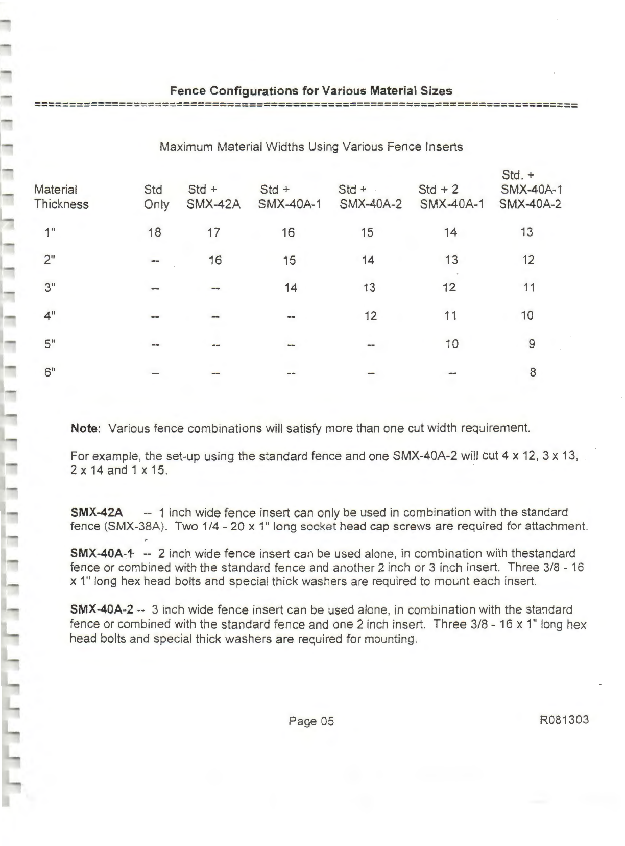
Fence Combination Guidelines
..
......................................
..
.........................................
...
....
Page
05
Trouble Shooting Guide .....................................................................................................Page
06
Adjustment
of
Valves .........................................................................................................Page
07
Instructions for Changing V-Belts .....
....
...........................
...
.............
..
...
...................
..
.....
...
Page
08
Suggested Maintenance ...............................
...
...
......
...
..
.................
..
...........................
..
....
Page
08
Warranty .................................................
..
.........
..
..................................
..
.....
..
.............
..
.
...
Page
09
Assembly Drawing .........
..
..................................................................................................Page 10
Diagram
of
Cylinder
...
.
...
.............
..
.....
..
.......
...
..
...
..
..........................................................
...
Page
12
Final Assembly Checklist
..
.........
..
......................
..
......................
...
......................
...
...
..
..
.....Page
13
Brochure Model 216 Cut-Off
Saw
..................................
..
.....................................
...
..
...
......Page 15
Material Handling Equipment Flyer ........
...
..
...
...
...........................
..
..........
..
...
.......
..
...
.........Page
16
Safety Guide for-Carbide Tipped Blades ...............................................
..
.........................
..
Page
17
Specifications
on
Compressed
Air
Filter I Regulators ..................................
...
..
.....
...
..
...... Page
18
Specifications
on
Coalescing Filters ................................................................................. Page
19
Whirlwind Return Policy
.. ..
..
..........
..
...
..
......................................
..
.......
..
..
..
........:................Page 20
Double Palm Button Controls .......................
...
..
...
........
..
..........
...
....
..
...
...
..
......
..
................ Page
21
R081303

General Safety Rules for Whirlwind.Cut-Off Saws
+++++++++++++++++++++++++++++++++++++++++++++++++++
1.
READ
AND UNDERSTAND THE OPERATING INSTRUCTIONS BEFORE OPERATING SAW.
2. If
you
are not THOROUGHLY familiar with the operation
of
the equipment you are assigned
to
,
ask your supervisor. instructor or other qualified person for further instruction.
3.
DO
NOT operate any piece
of
equipment while under the influence
of
any type
of
medication,
alcohol or drugs.
4.
ALWAYS wear eye protection (safety glasses or a face shield).
5. Remove loose clothing, tie, rings, watch and otherjewelry, and roll up shirt sleeves prior to
operating machinery. DO NOT wear gloves while operating machinery.
6.
GUARDS must be
in
place and used at all times.
7. CAUTION: Never put hands under yellow guard I clamp.
8. ALWAYS use a "push stick" or air gun
to
clear away chips and sawdust.
9. AVOID awkward operations and hand operations where a sudden slip or loss
of
balance could
cause your hand to move into the blade area.
10
.
DO
NOT work with lumber that
is
too large or too small to handle safely.
1
1.
Make all adjustments to machine with air and electrical power OFF.
12.
DISCONNECT the saw from all power sources (air and electrical) and wait for blade to come
to
a
COMPLETE STOP before making repairs or performing routine maintenance.
13
. NEVER attempt to free a stalled saw blade without first turning electrical power
and
air OFF.
14
. SHUT OFF
all
power sources (air and electric)
and
clean the machine before you leave i
t.
15
. CHECK SAW prior to operation for any damaged parts. Report any problems to your supervisor.
16.
NEVER LEAVE
TOOL
RUNNING UNATTENDED. TURN 0.FF POWER (air and electric).
Don
't leave saw until it comes to a complete stop.
1
7.
IF
IN
DOUBT
as
to what you should do, call WHIRLWIND INC. The telephone number
is
located
on
the
Air Cut-Off Valve Caution Label.
SAFETY
FIRST!

Cover Sheet
Whirlwind
Model 216 Pneumatic
Cut-Off
Saw
============================================================================
Before
we
get started, we would like
to
thank you for your purchase
of
a Whirlwind Model 216 Cut-
Off
Saw
. We realize we have a lot
of
competition out there and we truly appreciate your business.
In
preparing this manual we've tried to provide the answers to
most
problems that might arise.
However, if we've missed something, please give
us
a call. You should also
be
aware that
an
operator's manual has been provided with the machine.
We
encourage you to have each
and
every
operator spend a few minutes to become familiar with
it.
This machine, like every Whirlwind, was tested under power for 4-5 hours prior to shipment.
Nothing but the best components and raw materials were used
in
its construction. Like any quality
tool,
it
must
be
properly maintained to perform at its best. The operator's manual gives instructions
on
a few pre-operational tests. These tests should
be
performed at the beginning of each shift. If any
malfunction
is
noted, it should be corrected immediately.
Numerous safety devices are installed
on
this machine for the protection
of
your operators.
These
devices
must
not
be removed
or
tampered
with.
CAUTION: NEVER PUT FINGERS UNDER GUARD I CLAMP.
Again, we would like to thank you and welcome you to the large family
of
Whirlwind customers.
We'
re
confident you'll be impressed with our products and our service. With proper maintenance,
your Whirlwind Model 216 should provide many years
of
excellent service.
For your records, please fill in the followi
ng
informati
on
:
Date
machine purchased
________
_
Seri
al
number
-----------
Model number -216
Page 02 R081303

Set-Up
Instructions
for
Whirlwind
Model
216
Cut-Off
Saw
============================================================================
1. Position machine and bolt to floor.
If
infeed and outfeed tables are to be used, these should be
aligned with saw fence and table top.
When
alignment is satisfactory, bolt
table
legs to floor.
2.
Have a certified electrician bring
in
power
, connect machine, and check voltage. Rotation
of
motor should be checked while electrician is present. This should be
done
prior
to installation
of the blade. An arrow indicating proper rotation has been provided on the
arbor
access cover.
All wiring must conform
to
the National Electric
Code
, O.S.H.A. and local
standards
.
Power
Requirements
Voltage 230
Phase 3
Service Current (Amps) 50
Motor Running Current (
Amps
)
__
26
or
460
3
25
13
3.
Connect air line to the air
cut-off
valve on the machine table top (
1/4"
female
pipe
thread
).
Pressure gauge on the regulator should read
90
PSI.
CAUTION:
DO
NOT OPERA
TE
MACHINE
WITH
LESS THAN 60 PSI.
This machine is equipped with a filter, regulator and coalescing filter system
for
incoming air.
DO
NOT
ADD
OIL
TO
THE
AIR
SYSTEM.
The air cut-off valve is provided so t
hat
when the saw is not in use, this valve can be closed.
This cuts off air supply, bleeds system and allows the guard/clamp to lower. Use
of
this safety
feature should be encouraged
by
all supervisory personnel. A lock-out
is
also provided
on
this
valve. ·
4. A
4"
dia. exhaust fitting has been provided at the rear
of
the machine. This fitting allows easy
installation into dust collection systems.
Adequate
hose must be provided to
allow
for
the
movement of
th
e guard while the machine is cycling. -
Page 03 R081303

Model 216 Set-Up
Instructions
(Cont'd.)
============================================================================
5. Install blade on
saw
.
The
model
216 uses a 20" x 1" blade. Loosen bottom bolt and remove
top bolt from bl
ade
cover
on
front
of
machine. Loosen bolt on arbor access cover and swing
cover cl
ear
. S
li
de
blade
through the blade access slot and position on arbor. Verify rotation
with arrow on arbor access
cover
. Tighten arbor bolt through arbor access hole. Left hand
saws use right hand threads on arbor bolt. Right hand saws use l
eft
hand threads. Replace
access cover
6. Check work area to
be
sure it is clear. Turn air cut-off valve to the
"ON"
position. The guard I
clamp will come up quickly.
CAUTION: DO
NOT
PUT
FINGERS
UNDER
GUARD
I
CLAMP
.
Depress the green
"START"
button on the start I stop switch to turn on the motor.
Making
sure
that
nothing
is
in
the
blade
path
, depress the palm buttons.
Saw
should cycle once.
For cutting, the guard I clamp should be adjusted to clear material by about 1/4 inch. This
clearance is adjusted by turning the hei
ght
adjustment knob. This is
the
cast aluminum knob
located just behind
the
guard/clamp. Turn the knob clockwise to
decrease
the size
of
the
opening. To increase the size
of
the opening, turn the knob
counter
clockwise. This adjust-
ment
is
quick and
easy
when
air
to the machine is off.
7. After adjusting the guard I
clamp
height, turn the air cut-off valve to the "ON" position.
Verify
there
is
nothing
in
the
blade
path.
Quickly press and release the palm buttons. Guard I
clamp should begin to clamp and then quickly retract. If
saw
does
not perform
in
this
manner
. ·
call us immediately. Palm buttons must be depressed
throughout
the cutting cycle. After the
cut is completed, you
must
release the buttons before beginning
another
cycle.
CAUTION: DO
NOT
PUT
HANDS
ON PALM
BUTTONS
UNTIL
YOU
ARE
READY
TO CUT.
8. Installation of your Whirlwind
Model
216 Cut-Off
Saw
is
now
complete. Have
every
operator
read
and
understand
the operator's manual prior to putting this
machine
into production.
Sh
ou
ld you have any
quest
ions or
comments
on
our
products, please give us a call. Our
phone
nu
mber
is proudly displayed on the air
c
~t
-
o
ff
valve caution l
abe
l.
Page 04 R081303

Fence Configurations for Various Material Sizes
============================================================================
Maximum Material
Widths
Using Various Fence Inserts
Std. +
Material Std Std + Std + Std + Std + 2 SMX-40A-1
Thickness Only
SMX-42A
SMX-40A-1 SMX-40A-2 SMX-40A-1 SMX-40A-2
1"
2"
3"
4"
5"
6"
18 17 16
15
14
13
16 15
14
13
12
14
13
12
11
12
11
10
10 9
8
Note: Various fence
combinations
will satisfy more than one cut width requirement.
For example, the set-up using the standard fence and one
SMX-40A-2
will cut 4 x 12, 3 x 13, .
2 x 14 and 1 x 15.
SMX-42A -- 1 inch wide
fence
insert can only be used
in
combination with the standard
fence (SMX-38A). Two 1/4 -
20
x 1" long socket head cap screws are required for attachment.
SMX-40A-1- -- 2 inch wide
fence
insert can be used alone, in combination with thestandard
fence or combined with the standard
fence
and another 2 inch or 3 inch insert. Three 3/8 -16
x 1" long hex head bolts and special thick washers are required to
mount
each insert.
SMX-40A-2
--
3 inch wide
fence
insert can be used alone, in combination with the standard
fence or combined with the standard
fence
and one 2 inch insert.
Three
3/8 -16 x 1" long hex
head bolts and special thick
washers
are required for mounting.
Page 05 R081303

Troubleshooting Guide for Whirlwind Model 216 Cut-Off
Saw
----------------------------------------------------------------------------
----------------------------------------------------------------------------
Electrical Problems
----------------------------------------------------------------------------
----------------------------------------------------------------------------
1. If reset button must be depressed to re-start machine:
A Check wires
on
magnetic starter.
B. Check wires
to
motor.
C. Check incoming wire connections and voltage.
D.
Verify correct heaters are installed.
2. If machine re-starts by depressing start/stop button:
A.
Check wires to start/stop switch.
B. Check wires to door interlock switch.
C. Follow these wires to box and check connections at box.
NOTE:
1. Closely examine all rubber seals for damage while disassembling valves.
2. Repair kits are available for cylinder and pilot valve.
3.
Do
Not
allE:lw
sawdust or any foreign matter to enter valves or hoses while the machine
is
being serviced.
4.
DO
NOT REMOVE OR TAMPER WITH ANY SAFETY DEVICES.
Page 06 R081303

Adjustment
of
Valves for Whirlwind Model 216 Cut-Off
Saw
----------------------------------------------------------------------------
----------------------------------------------------------------------------
Your Whirlwind model 216 cut-off saw was run-in for 4 - 5 hours and then adjusted
to
factory
specifications. The double palm manifold requires
no
adjustment and
all
other valves should be
adjusted properly. Adjustments to cycle speed may be made for various applications. This adjust-
ment
is
outlined below.
CAUTION: CUT OFF ELECTRICITY & LOCK OUT DISCONNECT BOX BEFORE ADJUSTING
VALVES.
Cycle speed
is
adjusted by two alien cap adjustment screws located
on
the pilot valve. The upper
screw adjusts the speed of the cylinder expanding. The lower screw adjusts the speed of the cylinder
contracting. The speed ofthis expansion and contraction should be equal. The model 216 saw
should be adjusted to cycle 40 times per minute without lumber under the guard. When the saw
is
cutting lumber, cycle speed will increase. This is due to the fact that the guard
is
traveling less
distance. Maximum cycle time while cutting
is
approximately
40
cuts per minute.
NOTE: Exceeding 40 cuts per minute may reduce the life of the machine.
Page
07 R081303

Instructions For Changing V-Belts
On
Whirlwind Model
216
Cut-Off Saw
----------------------------------------------------------------------------
----------------------------------------------------------------------------
CUT
OFF
ELECTRICITY AND LOCK-OUT DISCONNECT BEFORE WORKING
ON
SAW.
1. Loosen four bolts which mount the motor
to
the table top and slide the motor forward.
2. Remove clevis (1000-47) from yoke (1000-4).
3. Slide V-belts around yoke
to
opposite side of motor.
4.
Remove two bolts which mount the left hand bearing hanger (1000-3) to the table top.
Note:
On
a righthand saw, remove right hand bearing hanger bolts.
5. Loosen two bolts which mount the right hand bearing hanger.
Note:
On
a right hand saw, loosen left hand bearing hanger bolts.
6.
Swing left hand bearing hanger down and remove V-belts.
7. Install new V-belts and reassemble. If desired, an extra set
of
V-belts can be looped around
the yoke
and
tied out of the way. This will make the next belt change much easier.
7. Pulleys must be parallel within 1/32
of
an inch.
9. V-belt tightness should
be
5/32 inch deflection with three (3) pounds
of
pressure.
10.
Note: Improper alignment or tension will result
in
excessive wear
on
V-belts
or
bearings.
Suggested Maintenance:
1. Check filter, regulator, coalescing filter daily for moisture in bowl.
2. Lubricate moving parts with lubricating oil.
3.
Check V-belts and tighten if necessary. (See item 9 above
.)
4.
Keep
inside of machine free
of
excessive sawdust. Special attention should be given
to
keeping magnetic switch box and palm button manifold clean.
5.
Keep
saw blades properly sharpened. Carbide tipped blades are highly recommended. These
blades may be purchased directly from Whirlwind Inc.
Page
08
R081303

August 23, 1982
Whirlwind Inc. Limited Warranty
-----------------------------------------------------------------------------
-----------------------------------------------------------------------------
Whirlwind Inc. hereby warrants, subject to the conditions set forth below, that it will repair or replace
without charge for parts or labor,
F.0.8
.
our
factory, any part
of
the product accompanied by this
warranty which proves defective by reason
of
improper workmanship and I
or
material within ninety
(90) days from the date
of
the original purchase at retail.
Conditions:
(a)
This warranty
is
extended to the original purchaser only.
(b) This warranty shall not apply to any defects or other malfunctions
caused by accident, neglect, misuse, abuse, alteration, modifica-
tion, unusual physical, environmental
or
electrical stress,
or
use
contrary to instructions accompanying this product.
(c)
This warranty applies only where the purchaser establishes
Disclaimer:
that the product was properly installed, maintained and operated
within the limits
of
normal usage. Any defective part shall be
returned promptly to Whirlwind Inc. upon discovery
of
a defect.
This warranty is
in
lieu
of
all
other
warranties
of
any ki
nd
and any other
representat!ons
or
warranties, whether expressed or implied, including
any
impli
ed
warranties
of
merchantability
or
fitness for any particular purpose
shall not apply, and are disclaimed with respect to the goods sold.
Whirlwind
In
c. shall not
ha
ve any responsibility for loss
of
use
of
the product,
loss
of
time, inconvenience, incidental
or
consequenti
al
damages. The liability
of Whirlwind
In
c.
is
l
im
ited to the cost
of
repair or replacement
of
defective parts.
For informa
ti
on concerning warranty service, please contact the distributor
from whom
th
e machine was purchased
or
Whirlwind Inc
.,
4302 Shilling Way,
Dallas, TX
U.
S.A. 75237 Phone (214) 330-91
41
FAX (214) 337-9572.
Page
09 -
R0619
98

0212-025B
CTEFC
MOTOR)
I
L)\//
Gw
1L
i<
:N
SON
1
1/
25
/ 92
!
I I
'
'
'
!
·1
'I
L
l I
'I
•
rJ,f
n
If
I''.
I
VVI 111 'i A,·
V'i
4302
Shilling
'N!J'
f
f l
nn
j l
'.
l i \
..
,!
'
\ '\ \ \ \ \
(I
A
i
il
.
Da
ll
as,
i
~xcs
7
5237
SMA21A
SMA09A
C2
REQ
)
~-
02:2-0039
CO
i'
lE
SHOT)
\
'
---Si'-'
~Xl
:B
iTil
.E
S
,~'h.
r.
55c:-'
,,
181 y
/-\
'....__
\\
/
~
~
SH
T 2/ 2
A!NO
S
i,;lX
26A
I
I
!
I
I
I
i

A_
8 / 13 /
0:3
~
~
S~A28A
SMF22B
SMX
49A
<2
REQ
)
1000-009A
(2
REQ
)
<CUSHION)
:i
~
lj.
~
'ltl
I
i
i:/1i'
:
·i1
/
Lf
:
'
tl~
i
i:
·1 I : , '
I
::
·
,,
'I
: i
:,!
: ii !
htil.L
1 d l
"?
\
?QQM3C
I ' '
.__p,-_
I . ' ' I
:1
I
CFRD
:I
:
'ii
I!
!
_sPC
'-
>l:-AIR-EAK) I :
i!I
::
/;
( ; 0
3t.
DETt:..RMIN~
!
i!
I '
CCY!_.
IN
C
L.
:i
.
ill
i!i
~
PI
LCT
'
VL
\/ .)
11
•
;l
:I· r
11
:· . H /
n1
',
:;i
i;
(' l I i
S
vx·.
B :
·'!
u L u
•.
L.L~
:
~
!
•)(.iL~
(
~~~~
SMA20A
_:_,
.
:,
:1
,I
02:2
-
C3
7A
--
'
l
.
~
; I
/ '
I
~
1000
-0044
<
S-:-lJP
/
S"7"
AR;~
.
-SMFJ8B
"----
SMX04B
S~
!X2
3B
I:
UL
-0
212-0026
~
~
~
CPUU
EY)
11
~----"-
~
·
i
s~~3~~-~Lc~f~)S)
,
1.1
:i
,
000-0049
(SHOCK)
:i
ii t SMF
45A
CCOVER)
11
l
S~F
4 7A CENCL.)
ii
I
i!
L---J
~
i
F'
'i
"-
'11
~V(~rlE
__,
S~Oi)
u1
it
II
- 1- 1 -
i,
: ; : i : '
!\
; I r
'I
' r j i
\
'\
;
f'i
!
'(
~
\ I I
'"
a·
'I"\
'\
Vv i
ii!
Y'
l!
i : J ! i1
·v .
I :S!;
f
.
~
.
,
I
r.v
·i
I
SHT
1/2
4302
Shiiling
W1J-f
Dallas,
Texcs
7
523
7
'A
INO

Econo-RamII™·11
'2"
through
4"
Bore, Lightweight, Non-Luoo
Hatd
Anodized
Alumlnum
1.ightwelght cylinder
body
:
unique
design
provide!!
streng1h and
eliminates
areas
or
contamination.
Pneumatic Cylinder.
Premium Quality and Economy In one.
lightweight
construction
and solid Non-Lube
design
with
proven
rellablllty make
the
Econo-narn n
Cylinder
the
high
performance,
long
lasting,
economical
choice
for your air cylinderapplicallons.
s·
throv9h
8" bore
h11ve
alu[Tllnum tubff with steel
tic
tods. See
page
Ill
lor
col)structlon
.
lfr>nd~
oncl C"r'.I
"'"
r1
rcr<
<
•1Jn.
I iqlttw,..1gl1f
Al1111
11nur11
hln
·
.
Y~
!'1:
11
--
;11~
;)n()(hJ"''J for
111
;1
JirTI\
llll
,
nrto•.rn
n
rr
~'.i
l'"
,
t
.J
11
u·
PrSfOn
IOrJ
lip
•
'l~l
:
wipPr
(0111Li
1n
rt
l1
0n
1$ 1.
rnnplnlPly
~ri
ll
r.oo
1p
<?
11
s:i1inq l
<H
rrro
fP~k'1'J"
;
1t
_
.-..~
;ill
rrr
so;
1ir
P.r;
VJ~PP
'i
JJ'f.!
~·.- 11
re
1
11
,
(Qll
lrt
m1n;tfiut1
Olll
r1
IPllOJ:'ll1r
:
s~rvir.~
Rod
Oland
lhrr.aded.
hrome
gtond is
exl'!r
·
nally
1r.mov~1~,.,
witlto11t cylindPr
di
s
assembly
for
ea
~
y
malrr111nance.
Che;ck
Seal
Cushions•
For
lncrwased
ProductlYfly
and
Maidmum
Performanc.
The
cf'lcock
~•a.I
cu~hion
11
n.,..,.,
and
d\f'fP.J•nt
trorn
ordinftry
cuchiott deciqns.
rt
combine•
tl1t
'""""II
cApebilil\""
of
a
lipseaj
for
tllident
capture
of air lor ellnelive
cu~hioning
""""
check
valve
ac6on
lor quick <hoke
rfver.-1
.
lht
dpcign also
provldu
"llo"11no
cushions-
to
;os.ure
cushion
repealabtllly and long ti'9.
Al
tlm s
t•rt
ol
!IHJ
siroke In each dlroction. !lie
ch8d
va~
00siqn
allows
lull""""
to
p;9ton f3ce ¥tlth a minimum
pAS!l\Jr9
drop
for
maximum
power
strol<e
Addinon.I l>flntlits of ltle
new
clltel<
sP.•f
c1r.1hlorni
are
ine<ea!!ed prod\Jclivrty
and
!Op
pmforma"""
lor
l••tnr
cyclo
~.
minimum
we111
. easy
erdiustment
and
low
prenure
drop
~
...........
--
~
....
«JIOTt
.
n;,.,1't1124c.J
~~
r':9S::...
CA
,,~"'°"""
-
•(,..,_ff
. CT
IV).,
••
71•'
•
~"-"
..
'1A
404.)4t?'"'.r.1
.a.-....
..
J•.-a17
•n.1
-~i~
.H
,
~'IP'f(':l""'-c
••""
I
11•1» 9 181
-------------
·
------
-·
-
Thr.
b~•lc
c11<hion
d"ign
i~
option,. and 1v•il•blt on
P.llhtr
the
head
end.
cap
end or both ends
without
change
In
envelnp8 or
mounting dimensiofl'I.
I\
captlvo
~n
•djusti119 n&edle
Is
suppli
ed
lor
eaey.
pr&dff
""ltJSlmt~t
on
all
bore
sins
-~~~
·
,tte
•At.t0n
.
OH
21Slf'.)
4500
-~·~
·
~
·~1~1°"
4
c.,.
• 'fbronto
°""
·
t:•"'
41e
:
rs1
.•
~1
•
~:~
·
~~
.
!
Ut>
.
®
Cu~hion
Needle
Valve!!
make
preci~c
ndjuslfllent
quick
and
easy
C<iplive
cushion
dAsign
allows for salR
rnshion
hcljusling
while
cylinder is
under
prn~
StHfl.
Brass
material
lo
resist
corrosion
.
Tho
Etxino
n~m
11
piston
rod
a11d
cylinder
~~rrel
•
surl•ces
act
as
hlghly eflicir.nt
lubrk-A1nt
n1servoi1s,
mehrtahring their own
lubricant
film
.
Other
m:rnufactvrers pad<
grr~••
into
groovH
and pockets
•nd
c~ll
them r
esenmlrs
.
The
lad
ol lhe
ma""'
is
rhat
a,.
thosr
grooves empty
out
ovP.r
lime
.
grea
se '' being tranSf"O'ted Dul
OI
lhe
cylin~r
and
fnto
the
contro
l
sy~rr.rn
tomponsnts
::.nrl
1he
\lltrnospher9.
1he
ECQno
h:im
II
concept
elimtn,te•
th•t
problem by
maintaining
the
lubri
c.
1111
him
whero
~
bf,longc:
on""'
s8als,
llea<lf"ll/
surlac'ls, pi•lon
rod
11nd
cylinder
bore
.
Tho
rnsult
I•
alonq
l•stlng
cylinder with
E«lno
·
n~m
II
QUelily.
;r,~~O:-:!:'
0••
n.i
·
~•
.
Iii
~··
1~
.
,400
~
..
,,_.,.,.
•SN'fl•r-~
.
CA
310.
~
l'Ml-()M!
·~llf'd
.
tH
,,.,..,.,,
.
118l
·~r~i,~
Pl5ton
Aluminum Piston with nylon wear
b11nd
increases
cyllnder
Ille.
11limin:.Ces
mefal·
IO
·metal
contiicl.
Optional
magnet
piston for
use
with reed
or solid stale swrtches.
/\n~l'roblc
adhesive Is usr.d
to
p<Jrmanenlfy look
and
sP.al
lhe
piston
lo
11111
rod
Polls
N.I'
1
.F
prnls
arc
~t;indard
.
Clreck
Seal
Cu
s
hion'
fl
rn111d11d
lip
p1·.Jnn
~
n;rl·
;
lJli<lr.i
0
11
h1bru:
.111!
ftl
m to
1n
;)xlq
1i
111
hlr..
Piston
·
noo
-
Hmd
cflrome-
pl~hrd
and
poll~hccl
piRton
rod
of 100,
000
psi
yiPld,
hiqli
IPn
s
<l
c
slrr.n9tlt
sir.cl
c113e
hardened
10
50
·
~~
11
, tor reli;ible prnlorma<r
cP.
And
long
rod
seal
Irle, IAss lncliot1.
Anntomy
of Econo•Ram
II
S.1!11111
and
lubricant
Rotel)tlon
System•
nf)urided 5f'.lfinq lip
\jiirlrs
0"'"
lut)f1C<tnt
lll'::r-oa~
hlf'tll
l™:kfl'n'
Mm ,,..011;tr-Plf1ol1c1apng
•t
oft
f{Od
1.ces
out11r
ltfl
~,f~ns,.on
1mpro\
f
nd
f)ri
1n
C
lt't'l,l!S
hht
puwj
tl1m1n::1
ln
lhfl
/ ,_htbla1y. f8Sf51 rolfing
"<t
·d
lo• >ddr<!
luh•nhon
c-
--_.-;-
]
~
-
Orewong
not
to'
,---
-
-.-
-
.-
' •
..._
- r
-,....-r--r-
~~Pml~
•
~
·,
":~~J,HC
•
11'-
•on.
OH
:.:
1c 111
•'°°
• p.....+1
$our'<d
.
°"'
C
l!lf'
,,..,.,,,x;,2
14'9'1
inteQrity
h•briau'1
"'i\11
IU~
PTrE
P•tidec
• £""'-•d, CT
lO);r.-nt'
.""'
··'
• '"
•~~
..
~~
·
,'IC,..._....,...,
•
l"Ofl\m"'°
QI'\
\OJ
1
:nC'WW
e T\J•Ol'lo
Ont
.
C•"'
4
14?
~'
'""
'
•lKt>i,...
.
Ou,~
•
C•n
,,
..
8Jl
.l
..
, . '
Schrack
BeUovvs
40
a..J.490"'.l\l

Installation
and
Servi
ce
Instructions
:
2FRiooCSB
Pneumatic
Division
Nort
h
America
Richland
,
Michigan
49
063
06E,
07E,
12E
Fllter
/
Regutator
Series
ISSUED:
No.,,ember,
1ggs
SuperMdes
: May, 1995
ECHI
"7.t9Cl5
_&WARNING
Tc
,_,d
unptwdlcublll
try98m
_,~can
ca.-
pe,_,.l
Injury
and propeny
ll•nwgr.
• 01.c:onnKI air
-.p1y
.,..
~e
911
* Unee conMCl9d
IO
We
pl'Dducl
bet.,,.
lllMllllatlon,
~CK~
•
Clpemo
wnllln
ti>•
.,.,,.._..
~-
,.,_..,
lem~,
•nd
1>111er
condltlona
11-.d
on
lll9M
II--.
ctl•na.
Medium
......t
lie
mol.-..e
If
8INlillnl_,.,......
la.._
INclng.
SMvtca
a~ng
to,.._.._
--In
111-.1-.
INUllnlon;IMVlca.
and
--.Ion
of,,,_,..,._
-lie
,..norm.el
by
knowlM19Hbill
personnel
wlto
~
i-
pneum8llC
,.mucu
a
..
to be applllld.
Aller lrw1allatlon,
NMelng,
or
-rslon,
U-
aupply
llhcMllcl
lie cONWdoc:I
and
!ht
p-uct
198'eel
tor
proper
tunc:llon
and
lMUgt.
I auellllie
leai1a9t
LI
p
.....
m.
or
Iha produCI
oo.a
no1 oper11e property, do not put
lnlo
uu.
•
Wamlnv•
and
epecltlcaU-
on
th•
P"'duCI
•'-'kl
not
be~
by
p111nt.
ttc..
II
masking
la
not
poealble,
-ct
ycKW
loc:aJ
NpreNntall\lt
.
tor
roploc-t
label&.
Introduction
Follow
in
...
innuetions
when
insialling
. oper81ing.
or
aervUig
ll'la product.
Apr!i.cation
Limits
These i:irtici..cts
are
intrd-2
for
use
in
g-.1
IMPOI•
cOmpr8Aed
mir
sysl8mS
or'iy.
O~ng
Inlet
PreHure:
with Polycarbonate Bowl
with Metal
Bow1
kP•
1000
1700
paig
150
250
bar
10
.3
17.0
Note: The maximum recommenclad pressure
droi;>
for • par1iculate
ftit11r
is 70
k?a
(10
psig, 0.7 bar).
Ambient
Tempereture R•no•:
with Polycarbonate Sowl
with
Metal
Bowl
Symbols
-4
!/®~
FilterfRegul•tor
06E
&
07E
Installation
o·c
to
s2·c
(32"F
to
, 2s•F)
o·c
to
ao·c
(32"F
to
17S"F)
Filt.,/Resiulator
12E
(Coal•scin;
Et.m•nt)
1.
The
ftfter/r"9ula1or V.Ould
be
inslaJed
with
r...,.....,le
aa:Miotilly
to.-
......Ce
wnenever
possible
-
r~r
servjee
kits aro llllDilable.
Kaei:>
pipe
er
tubing
lenguis to a min.mum
With
inside
deil/1
and
tr
..
of
cfort
and chips.
Pipe
joint
compound should
oe
used sparingly
and
aop~ed
only to
the
male
pipe
-
neiv~r
into
the
1emaJe
port.
Do
not
use
Tenonr
tape
tc
seal
pipe joints -
pieces
l'lave a tendency to break
off
and
lodge
inside the
unit
possibly
ca~
i
s
1
ng
malf\.:nCDon.
Also
.
new
pipe
or
hose
shouk::I
be
ITTs~lled
between
!Tie
h!ler/regula1or and
equipmwrt
beinc;
pn:t-=ted
.
2. The upstream
pii;>e
work
must
be
clear
of
accumulated dirt
end
6quids.
3.
Sel~
a filter/regulator location
a..s
close
as possible
to
tt>e
equiimient
being
pro1ec:
ed
.
•. Install filt..r/regulator so that air flows
in
the direction of arrow
on
body.
S. Install filter
/r
egulator
verocally with the
bow1
drain
m~sm
at
the bottom.
Free
moisture
will thus drain into
!tie
sumi;>
rciu
iet zone") at !he bonom of
ttie bowl.
6. Gauge ports aro located on bolti sides
cf
the fttt..r/regulator
body
for your
corven
ience. It
1s
necessary
1D
install a gauge or socket pipe plugs imo
eact\ port Cluring
installabort
Operation
1.
Botn
rree
mo1Sture
and
so
l
lCIS
are removed
auiomancally
t>y
!Tie
tllte<
.
Ums
..,.,,
coa
lesc1
"9
elemerm 10.9. 12E
-•es)
also remo-e
01
1.
Foe
a:ialnong
units.
~
5 micrometer or•ftft81' is
recommendac
to
proteci
and
pftllong
the
life
of
tne
coaiescen1
finer
•em..,,,_
z.
Manual
or81n
fillen
must
be
or
..
necf regularly
betore
the
separated rnoll!Ure
and
01
1reac:nes trie Doncm
of
tne
baflla
er
lll"CI
Ci!,.
.
J. The lllter
element
snouiO
be
remo,_,
_,.,.,
r~.d
wf'len ptes&Jre diffarmni&J
acrou
the
Mer
1s
69
kf'>a
(1
o
P'S19)
.
.t
.
Baler~
turning en tne air SUPPiy. turn tne knob '®n\llreiocXwW1 until
comprus1on
11
rat-
lrcm tne
i:ir.....,.
canlr'OI spring.
Then
un
llnob
dCdrWtM
and
lldjust r99ulalDI'
ID
Cl--1
do...-m
pr.aura.
This
l*ll'ltS
llt-..ut•
ID
build
up
llowly
1n
uie
downnum
line.
5.
To
dac:r•H
r89ut.lad
i:ireuure Mllings.
~
reset
flom
•
pr-..
tower
tllan
1l'le
~nal
Mfting requited. E.umple,
lowering
'lh•
--.:lary
prtlSSUle
ifom 550
ID
.t
10
kF>a
(80
ID
50
PllSI)
is Dell
acc:cmpishld
by
dropping the secondary
~reuure
to 350 kPa
(SO
psig).
tnen adjusling
upwatd
ID
410
kPa
(60 psig}.
6.
When
desirad secondary
preuure
fftllngs i'la.,,. been reached, push the
knoo
down
to
lock
tl'us
erasure
setting.
Service
.&
Caution
: Ol1conneet
or
shirt
olf
air
supply
anc:t
ellllauat Ibo prlmery
and
ucond•ry
prnaurH
blloro
Mrvicinv
11nlt.
Tumillg
t11e
Mlju.Ung
knob
counterdoeltwia•
doH
not
wnt
downatreem
prHeure
on
non-
rell9Ying
r.gul.iorL
Oownatraun
preuur•
must
bl
ftntecl
before
HNici119 regulator.
Hota:
Gruae
p.c:lrets
arw
aupplled
·
wtth
lclb
It.
~
1u-..<wtion
of
-la.
UM
only
mineral
baled
groaH
or
oll&.
Do
not
usa
synthetic
olla
lllch
~
Htera.
Do
not
uae
alllconeL
·
Note: Alter Hl"Vlclng unit,
tum
on
air
supply
•nd
ed)uat
.-gulldor
"'
v..
dHll'9d
downstnem
prn1ur1.
Cheek
unit
tar
leakL
Ir
laak-ve
occ11ra,
do
not
operate •
condllCt
repair•
•nd
retest.
Servicing
Filter
Element
-
A.
06E
& 07E
Units
(Refer to
F"igure
1.)
1.
Unser-the
bottom
lhrudad
collar
anCI
remove bowl.
2. Unscrew
the
baffle
and than remove lalement.
~.
Cean
all
internal
!)arts
and
bowl
beiore
ru.uembling.
See
polyartlcnate
bowl
ouning
sec:ion. IMPORTANT:
The
06E Filler/R19Ulatcr will not operate
prooerly
ff
11-.e
deft~.or
(or
rubber
spac11r
ff
using an 06E ads>rt>er) is not
installed
i;>roperty
.
The
06E deflectcr (or rubber
spKW)
must
be
instaAad
berween
!ti•
filter
s1em
and the filter body.
.t.
lns;all new element
S. Anacti balfle and finger tighten firmly.
6.
Rei;>
lace bowl seat.
lightly
lubricate new seal :c assist wilh retainng it in
JX>sition
.
7. Ins
tan
bowl
i
mo
body
and
tiQht.,, collar: torque:
OGE
eollar • from 3.2 to 3.6
N-m
(28
tc
32
in-lbs).
07E
collar -from
5.-1
to
5.9
N"fTl
('8
to
52
in-lbs)_
ffiwARNING
FAI
LU
RE
OR
IMPROPER
SELECTION
OR
IMPq()PE,R
VSE
OF THE PROOVCTS
J.NO
I
OR
SYSTEMS
DESCRIBED
HERElN
OR
RELATED
ITEMS CAH CAUSE
CEATh.
PERSONAL
INJURY
ANO PROPE.RTY OAMAGE_
nus
c:ocumton
l ano
oltler
nbmaron
tran
The
~-
u subSldra11es
and
a..aD"IOrlZ!'d
ois
rr1bu
1o
ri pr
O'll"Or
ptOduc
uiC11or
sysrem options
bt
h..nner n¥esu;.a1ion
:r,-
users
h•""9
le<:Mc.aJ u;>erns.e. n s
.mponan1
NI
you
IJ\liyle
al
up«2S
o1
pir
~
.
nouding ronsPQuences ot atty
'2iurt
anc
r
~
tnt
ntormatian
conc:em:ng U\t
p1oouc:1
01
s~tem
ti
t~e
c:urren1
proWc
ealllog.
Due
10
1111
v.11•ry
of
oporatng
c:oncrhons
ano aophc;uons
ltw
11'\es•
prodvaS
OI
J:yS1ems
. tne user. 11\tough U O'llll'I
an.iys1s
and
IHlf'li;I.
lS
sc~ty
r
~soonsrtH
ror m&k.-.g tf'le
MaJ
HledlOn
of
U\e
pttOJas
.ana
sys1ems
MlO'
usu
r
f'\9
in
a.
1
aJ
I
pertormanet
.
s.1~
and
~,n.,g
requ~ts
ol
17\e
apphatron arr
me1.
The
proouc:s
descn
b
eod
hete.n
. i"tduc:hn9 wflhOUI
limitation
,
product
!m:atutn,
soe<:n<:.1
""1S
.
Ots'9"'
·
•vol•c•ir-;
and
pralg
,
•rr
s.uOjtd
1c
c:l\11191
O)'Tht
C<imlW!Y
ano
o su
bSJCha
r
l!S
ar
:lil
y
ume
wrU'tout
no1ce.
EXT!'IA COPI
ES
OF
THESE
I
NSr.:lUCTIONS
Ai:IE
AVAJU.BlE
FOR INCLUSION IN
EO
UIP
),(0
/T /
MA
INTENA.NCE
MANUALS
THAT
UTIUZE
THESE PRODUCTS. CONTACT
YCUP LOCAL REPRESENTATIVE

1 I
I
UI
06E, 07E,
12!::
Filter
/
Regulator
Series
B. 12E Unrt1
(
Fiel~
:o
Figure 2 ;
Mol
t:!
~
eoll&J
S't2
l.J
ona. y wnde uf\SCr.....,ng
1nd
removing
t>O'flri
n.a
..... enc
~P
anc :ne remove
•ement
.
(oO
no
t remove trir
uotd
rod.)
C:11n a
ll
1n l
t<n&J
P&f!l i/10
001'11
()flOll
r
UUMlbl•t19
.
• l
nN
ll
n..,.
l<IM\t<lc
Anac:J'\
8"'1(1 c..o
and
finge n9nten ,;rrrvy.
6 Reoiacr oo.., u
ai
L1gnny
1
utvQle
,_
MAI
;o
ua
1S1
WTtl'I
r
~n1ng
11
1n
ccsroo
n.
Thrt10
OOwi
into
c:oll&r
nar.c: 09men
uncl
t>owl
SlCPS
IQ&tl'IS1
colll
r
Serv
i
cing
Regulator
-
A.
otE
&,
07E Unit.I ·
(R
ele<
:o Figure 1 )
1. Di
1tf\9a9•
II\•
ao1u1nn9
lllloo
Oy
pulli"'il
uc:iware. Turn adjulDrlQ
knob
count
erc1ockw'rae
until ttie
~omp
r
aa.on
is
r9'eued
trom
th•
ptMsu
re
COl1\IOI
soring.
2.
Remcn.
lh•
OOMC
I and
Dow!
u.saml:IUtH by
unw-..g
,,.,.
two
1hr-ed
COllAIS
.
3.
Remove
oiapnr119m
1.ssemo
1y
lrOm
bonnei
.....
-cry
.
' ·
Romove
lllt•
llll<T\.
~n
...
..
...,.,
l
P<>Dl>el
.....,,,Dty
.
popp.i
rau-n 1pting,
(
Nl
tl
.-n
ana rts o-nn;s.
5.
Clean
and
carelully
1n111ec:1
!*II
tor
-
or
dam8qa.
If
~
i1
n«:nwy
......
pans
lrOm
1.-.c•
kJtL
Clan
bOwl
s..
polyall1)al-
~
durw19
MCllOn. -
6. Lubncat• o-rin;
ana
""
lllldMg llMla
will'!
o-
~
in
.-vice
lcils
.
7.
lnm
n
poppe!
1'91Urn
1pnng.
poppe
t
usemciy
. (M91)
naer
t
ltld
ils
CMing1
,
end Allw •em. IMPORTANT:The06E
Filtw/FlegUmlor
will
not
opw
..
~
if
ine
att1ec:!Of
(or
rullbef
1pacer
if
..-ig
111
o&E
lldeorller)
11
not
irmalled
prapwty
. Th•
06E
dlfllC".o
r
(or
Nllber spacer)
must
be
1nstalltd
~
the
aner
nem
and
1111•
ciooy
.
8. l
llSllll
fill•
11emen1
and firmly tigl'len battle
°""'
tl'le
ftll8<
-.
9.
lnsWI
ctaonr
119m
asHmo
1y
into
botV\11
asH'TIOly.
Auemc111
bonnml
&Nembly
Ill
bady and Dgi'!ten
lnrMO«I
eollar from 5.4
Ill
5.9 N-m
(
~
lC
52
in-lbl).
1O.
lnSllll
tlOwl
il"llO
body
and
tJQlllen
cellar:
1Drqu1
:
06E c:olllr -
trom
3.2
to 3.6 N-m (21 tc
32
irHlllJ,
07E
c:ollet
-
fn:lm
5.4
to
U N•m (48
ID
52 ir'Mbl).
a. ,
2E
Unlta •
~-ID
Figll'I
2.)
i.
Oisen;ag"
!he
1cliusti"'i1
knob
by
pulling
upward.
Turn
adjusting knob
· •
C":>u:'119rdoc:kwiH
l.C'ltil
lhe comi:irwuion
is
rllelsld
tom
Iha
preu.n
Ca'llrOI
•oring.
2..
1-1.....,...
Ill•
bolvlec
UMmllly
ey
urwcr-.ng
llS .,.,_caller.
3.
Rmmcve
the
bOtlDrn
eolllr
and
i:lo'M
11
an
int99ral
lril.
Nole:
The
,........
flow
adaplt<
and
..
.....,.
~Illy
lllcMd
r.main
in l"OPlt llignmWll
willl
the
c:onar:
!hey
.,..
t.IO
in
plac:•
tly Iha
o-mg
betwewl
thl
lldapw
and
the
collar.
3.
Remove
dilptngm
assembly from bonnet
uaambly.
·
"·
AllmOYI popp91 assembly. poppet
-.rn
spring,
1-1)
inMrt
and
Ila o-rings.
S. Clffll
and
car•lully
inspec:
partS
tcr
wear
or
dammga.
If
raplacamw
is
necessary,
use
parts
from sl<'l!C:t ld!s.
6. Lubncate
o-ring
ano v
...
paclung
IUls
wiltl
grnse
ft>und
in
HNice
lci!s.
Tl-IRUST
KNOB WASHER
SF'RING
GUIDE'
AO.JUSTING
SCREWASSY
VENT SE.AL CONTl'IOL
S~NG
(RELIEVING
ONLY)
DIAPHRAGM
COL
LAR
(TOP) ASSEMBLY
0-RING
0-RING
(IJPF'ER INSERT)
(LO
WE
R
IN
SC:R
T) SEAL
BCOV (UPF'ER
!IALANClNG
)
SPCllNG F'OF'PET
(P0
PCET
ASSEMBLY
RE7\.JRN)
o.
;:,
1NG
_.....-
INSERT
ASSEMBL
V
(INCLUOES UF'PER
SE.A
L BALANCING SEAL)
(LCW
E"l
COLLAR (BOTTOM)
BAL.ANC;NG)
DEFLECTOR
REIAINER
ELE.
....
ENT FlLTEA STEM
BAFFLE
BOWL
GUARD
Figure
1:
06E
,
07E
2FR1
OOCSB
i
nsta
ll
po~pet
f
ltu
rn
spr
1
nog
.
:x:>oc
et
AUeme
ny. (
su
t) ina.ert
and
ns
o--rings..
l
nsta
1I
01apnragm
u.se
-rio1>
1
n10
bonne
1
as11mbly
.
Alaemble
belnn8'!
a.ssemory
to
bod
y 1nd
ogn1en
011uo
ed
collar
trom
5.4
IC
5.11
N-m
(~
1e
52
1n-IOi
).
9 l
nrt211
boftom collar ano
t>Ow1
sut>&£nmbly into
body
.
I.gm.,,
c:cnar lrQTl
5
•to
S.9
N•m (
411
lo 52 1
n·I05
I of torque.
Safety
:
Polycarbonate
Bowls
CAUTION
~I
•
Dowis.
t>eong
ntls-•11
ano
ICIUQl'I
,
111
ldul
br
u.se
-
Filters
&nd
l..u
tmca1ors.
They
111 1urtaD'•
tl:w
..,.
in ftOnnal
W'lduatna.J
_,,.,,,
...
Dul.,_
l'Cll
De-.C.,
•w-•...,,-be~
Ill
Otrec:!
IUf1lqll.
1111
tmpac
-
""'
...........
-1118
of
.,.
1.-d
ra"o•
. As
w.th
moa
t
plesucs
.
tom•
~nem1cal1
can
caiu1a
damag&.
~i.
"°"''
.,,.....,
""'
oe
--
"'
c:Nannli.cl
~
ketones
.
••en
and
c:-n
llCDllOll. Th.,- lllOuld
nol
be
UMd
1n
air
~
-••
comor•aon
ar1
lu""""'9d
-
11r
....
-.i
lluift
9UOI
11
p,.....,,_
-.,,,,~~
""-'
bowls
.,.
,__Ml
--
amlltenl
llll'ldJot
.................
-
-c:am---~----b-ol
,.,,,.
"""'
-.
but
"""'*'
not
oe
.-
-.
11n1ng
-·
or
-.,..
prnan
t
or
In
1111!
laden
llrTIO&jll\tltn.
Con..-i
tnl
llclDry
tor
ipedllc
TC
Ct..EAN
~LYCAl'l•ONATE
aowu USE lllLD
~
AND
WATl!R
ONLY!
00
NOT
..
, deanoong agena
a.en
u
ac-
.
tleta-
.
C111M1n
lelrlehlond•
.
guolin•
•
.,..,_,II:.
,_,,.,.dllftllll"9.
....
plMk.
-
9"1'CI
are
llUlllllN-
ID<
I009d
-
Of
po.,...,_
- -
-allad<
_,
occ:vr
.
WARNING
To
e.oid
~·
-
rupLtr•
!NI
can-~~
or
Pf01*tY
a.mag•
. oo
not
--
bow4
preuure
of temperature
ratings
.
F'a~te
_
,_
• 150
psig
(1
030
kF'a
Jornaur•
tDng
...a arTWXJmt.m
iampermn
rall"Q
of
52°C
(1
2S'F).
MAINT'EHANCE
SERVICE
KITS
Element
Kits
s
J,liaan
'Cl
Mic:rt>n
Grild• 6
Grade10
RlliiMig
R89'Jlalor
Repair Kit
Non-Refieving
R
egulator
Repair Kit
UP
SEAL
COLLAR
(BOTICM)
ADAPTER
(REVE"lSE
FLOW)
DIE
11".
311'
"
112'
F'S702SB
F'S70
1
SB
NIA
NIA
PSilOSB
F'S
711
S8
07E
12E
;;.~·.
1/2°
l.3W
318",
112"
•
31
...
F'S802SB NIA
F'SB01S8
NIA
NIA
PS8&4SB
NIA
f'S885SS
F'S810SB
F'S886SB
F'SS
11
SB
PS887SB
RETAINER
0-RINGS
THREADED
ROO
COALESCING
EL:MENT
BCWl
(METAL ONLY)
END
CAP

Installation
&
Service
Instructions:
2C100EP
Pneumatic
Division
North
America
Richland. Micnigan 49083
1/6" ,
1
1
~·
&
J/S"
Economy
1/4", Jte· &i12·
Compact
:i
1
s·
, 1/
:2"
&
314~
·
Standard
Coalescing
Filter
Pneumatic
LL
WARNING
To
1vo1c
unpredlctabl•
•v•t•m
oenavlor
tn11
can
c•u••
persona
l
in1ury
1na
property
<11m191:
Ol1connac1 alec:trlc1I
1upply
(wl'lan
nacauary)
t>alor•
lnatall1tl1>n,
••rv1can;,
or
co"v•r•1an.
Ol1conn1ct
•Ir
1upply
and
<l•Pr111u
'·fza
all
air
lln11
connected
10
tn1•
proouct
tMtfar•
'"•t•U•uon
.
..
rv1c1ng.
or
canvers1on.
Operate
within
the
m•nutacturer'
1
•SNCill•d
preaat.1r1,
temperature,
1nd
orner
conclltion•
lla&eid in
th
..
•
lnatructlonL
M..Slum
mu11
t>a
moialur
..
lrH
It
amoianr
l•mpa,..tura
ia
below
fr•e&ing.
Service
1ccordln9
10
proc:ldur••
ll•led
In
lhau
ln11rucilonL
lnstall•tion
.
aerv1c1
.
and
converslar1
ct
thne
products
muat
b•
p•rtormecs
by
k.nowl1dge1tU•
p'
ersonnal
who
understand
haw
pneumatic
proClucta are ro Ila
appllld.
At1er
ln•Ull•tlon
,
••rv~clno,
or
c:onYer•ion,
alr
and
electrlcal
auppl111
~wnen
necHN'Yl
1nou111
II•
c:onnec1a0
and
Ill•
product
!Hied
tor
~roper
!unction
and
IHk19a.
11
audlbl•
IHilag•
la
pre
..
nt,
or
11'1•
product
do11
no1 opa,..11
properly,
eta
no1
pul
inlc
u
...
Warning•
and
1paciflcstl1>na
on
tll•
product
al'lculd
ncl
b•
covered
by
paint
.
tic
.
II
m11kln9
la
nol
pPHlbl1,
ccn11e1
your
toc:1I
r•presantatiYt
for
r•placemant
labels
.
&cAUTlON
Polycarbonate
bowls,
being
transparent
and
tough.
are
ideal
for
use
with
Filters
and
Lubricators
.
They
are
suitable
for
use
in
normal
industrial
environments,
but
should
not
be
located
in
areas
where
they
could
be
subjected
to
direct
sunlight.
an
impact
blow,
nor
temperatures
outside
of
the
rated
range
.
.A.s
with
most
plastics,
some
chemicals
can
cause
damage.
Polycarbonate
bowls
should
not
be
exposed
to
chlorinated
hydrocarbons
,
ketones.
esters
and
certain
alcohols.
They
should
not
be
used
in
air sys.terns
where
compressors
are lubric.:ited
with
fire-resistant
fluics
such
as ohos;::nate
ester
and
diester
types.
Metal
bcwls
are
recommended
where
arr:bient
ar.dlcr
media
conditicns
are
not
compatit:
le
with
polycar::onate
bowls.
Meta
l bowls
resist
the
ac:icn
of
most
such
solvents
.
but
should net :ie c:sec 'Nnere stror.g
ac:ds
or
bases
are
present
or
in
salt
l
aden
atmosphe
res.
Consult
the
fac:ory
for
spec
ific
recommendations
where
these
conditicns
exist.
TO
CLEAN
POLYCARBONATE
BOWLS
USE
MILD
SOAP
AND
WATER
ONLY!
DO
NOT
use
cleansing
agents
such
as
acetone.
ben::ene
.
ca
r
bcn
tetrachloride.
gasoline.
toluene.
e!c.
which
are
::ama~
;
ng
to this
plas:ic.
ISSUED:
August
.
2000
Supersedes:
February,
2000
ECHI
?27llO!
Application
Limits
These
products
are
intended
for
use
in
genera
l
purpose
c:impressed
air
systems
only.
Maximum
Recommended
Pressure
Drop:
kPa
PSIG
Coalescing
Filter
70
10
With
Polycarbonate
Bowl
kPa
PSIG
bar
0.7
bar
Operating
?ressure
Maximum
1000
150
10.:l
Operating
Temperature
Maximum
s2•c
(12s•F)
Operating
Temperature
Minimum
o·c
(32°FJ
With
Metal
Bowl
kP-a
PSIG
bar
Operating
Pressure
Maximum
1700
250
17.0
Operating
Temperature
Maximum
eo·c
(17S'F)
Operating
Temperature
Minimum
o·c (32"FJ
05
/
15
Series
With
Metal-
Bowl
and
Auto
Drain
kPa
Operating
Pressure
Maximum
1000
PSIG
150
Operating
Temperature
Maximum
Operating
Temperature
Minimum
ANSI
Symbols
Coalescing
w/Manual
Dl"ilin
so•c
ci
75'F)
o·c
(32"F)
L:hWARNING
bar
10.3
FAILURE
01<
IMPROPER
SEL!:Ci10N
OR
IMPRO?ER
USE
OF
THE
PRODUCTS
AND.OR
SYSTEMS
DESCRIBED
HEREIN
OR
FIEU.TED
ITE!>.!S
C.O.N
CAUSE
DE
....
TH,
PERSONAL
INJURY
AND
PFIOPEi'ffY
OAMAGE
. .
This
c:cc:.Jment
and
::Hr~l!'
r
infcrmaucn
trcrn
?arker
Hannifin
C::irporation
,
its
su~s1diar1es
anc
aulhOflZf!'d
di
stnCL.:tcrs
;:>rov1de
produr::
and
/or
s
y
st~m
:iptrcns
fer
~r:~er
inves111;3ucn b;r'
users
having
:e-c:imcal
exc:er:1se. II
1s
1mpcrtan1
tha1
you
analy:!
ail asoec:1s
ol
·(Cur
acc:licauon.
i
r.c~L.:d1r.;
c::inst!ouence-s
of
any
tailur~
anc
revi~
the
intcrmaticn
:::ncerr.in9
:he
prcc~c
:
or
sysrems
1n
~ne
C:.Jrr!'!nt
~roduc:
c..atalcg. Due
:c
!ne
·
"anery
of
ope
ra.ur.;
::onditions
-.nc:
•~ptu::.ations
for
these
produos
or
sys1ems
.
!he
user
.
inrough
1ls
own
analysis
a.nd
!!!Sling.
is
solely
rescons1ble
for
making
:he
tina
l selec::1cn
ol
the
products
and
systems
a.no
assuring
lh•U ail
?er.ormanc~
.
s•t~!'y
and
warning
r~u1rements
c f
:rie
ai:plica11on
are
met.
Thi!
;:irc~ucts
desc:~11:ec:
herein
.
inclu~ir.g
without
limitation
.
product
fea
t
ures
.
spec:
:fic.ar1ons.
oes1gns.
a
....
a11a.~1hty
and
pric:ng
.
are
sub1ec.1
to
c~ar.;I!
:::,y
Parke
r
~ann1fin
Cor;iorat:cn
a.nd
its
subsidiar
i
es
a t
any
lime
·..,i1:-iout no1u::e.
EX'7;<A
COPIES
OF
THESE
I
NSTFIUCTIONS
ARE
AVAILABLE
FOR
I
NCLUS
I
ON
IN
EQU
I
PMENT
/
MA
I
NTENANC!O
MANUALS
THAT
UTILIZE
THESE
P"IODUCTS.
CONT.O.CTYOUFI
LOCAL
REPRESENTAT
I
VE
.

Economy, Compact, & Standard, Coalescing
Filters
lorqu•
:
~
.
/s~;"1
...
1~~i
·;
"b
-
Not•
O"anution
Of
.I.I
I
CPI
Pana
When
Oi•HNfTlllllng
At
A&Mmblin;
!CPI
Ar"11W
Opl'Uil•
Body...,._,
~
~
r
0 I I
Co-n11
Fllt•rs
I• I e
@WltnoutOP!Onty
.e .
~
$i
•
fE&:clftOmy,
9 I
'-e'
- / CompaC1
~Q0c.-.:~.
-·
~
i
(J
. -·
~
,
lStanoard
)
-·
· ( . /
..
·-···
·..
~
·
-
too 0
·
~Body
Compac:t
'
Standud
Filler
Body
·
---
1
O..l'ift9~
(L.ogta
Al
·
Bollom
01
Tllr•ad•)
r---._
1 Fitter Holclar
M_
(HandThghten)
U----
Element
~~
~---
1
s.m.
.
0-nn;~
Economy
CD-
{MandT191tt•n)
.
(tJ••
Appropriate
Sin)
©:Zl
Potyearbcnate
Bowl
(SHWaming)
(Do Not
Scratch
Internal
SLOr1aCts)
I
~
~~,___
FloLaining
~
C.:illar
I
(Hand
TiglHan
PILOI
1/<I
Turn)
@ UghtJy:grease with
provided
lubricant.
,7
'.
lnspec
fer nicks.
sc~atc~es
,
and
surface
imperfecticns.
"-'
If
present.
reduced
service
life
is
prooat:le
and
future
replacement
should
t:e
planned.
©
c:ean
witlJ lint-free c!
oth
.
Installation
1.
1'1e
niter snoul
C:
t:>e
i
nstal
led
w1tn
.
reuonable
accessibility
rcr
se
rvice
wneneve
r
pcss
1ble -repair service kits are
ava
11
ao1e
Keeo
p1oe or
tuc
1
n~
lengths
to
a minimum
with
s1oe : 1ean and
~ee
of
d111
ana
cn1ps
.Pipe joint comoouno
s
ri
ou1c
:ie
usea
soaring
ly
anc
apclred only
to
trie male
01pe -
neve
r
~
nto
tne female i;:er:. Do not use PTFE !3pe
to
sea1
p1oe
10
1nts -01eces have a tenoency
to
break oft
;ar.o
l
odge
1ns1oe
the unrt. possibly causing maltvnct1on.
Alsc
new
p1oe
er
nose
should
be rnstaJled
betw~n
trie
filter and
equipment
oe1ng protec:ed.
<-
.
The
upstream
p1
ce
work
must be
dear
of ac:eumulated
c1n
and liquids.
:;
. Selec: a lilter l
ocauon
as
dcse
as possible to the equipment
being
proteeted
and
upstream
of
any
pressure regulator.
4 . Install filter so :nat air
nows
in
!tie
direc:ion
of
arrow on
tlcdy
.
• . Install filter
vertcally
with
bowl drain
mechanism
at the
bottom
. Free
moisrure
will
thus
drain
into the sump '.quiet
zone·
at
tne
bonom
of
the
bowl. I ·
Operation
and
Service
1.
Seth
tree
moisture
and solids are removed automatically
t:y
!he
filter.
There
are
no
moving
par.s.
2.
Manual
drain
filters
must
be
drained
regularly before the
separated
moisture
and
oil
reaches
the
bottom
of the
lower
baffle
.
3.
Tne
coalescing
filter
..
element
should
be removed and
replaced
when
press
.
ure
dif:erential
ai;ross the filter 'i$ 1O
psid
.
The
differential
pressure
indicator,
located on
top
of
tne filter bedy. gives a visual
indication
of
the pressure
dir.erential
across
the
filter
element.
Ct-.ange the filter
element
when
half
or
more
cf
the
orange
piston is a.bove
the retaining
ring
when
air is 11owing. For units without a
differential
pressure
indicator.
pressure
differential gauges
should
be
used
to
determine
when
the
maximum
r1PCommended
pressure
differential
has
been
reached
.
~
.
Shut
or.
air
supply
and
depressur
i
ze
the
unit
, before
servicing.
5. At:er
ser1icing.
apply
system
pressure
and check for air
leaks
. It
leakage
occurs,
Do
Not
Operate
-
conduct
servicing
again.
Service
Kits
Available
Cescriplion
Economy
Compact
Standard
1;s·.
114
•
&.
:i
:s·
1/4·.
318"
a.
i12·
:li!"
.
112"
AtJW
: :ement '<its•
Grace 5
Ps;24P
PS724P
PS824P
Grace
~
O I PS3:00P
PS7::!0F
PSBJOP
:;;:
1
:=2::a1
r
\(i
t
PS781P PS781P
?5781
p
:O
·
ec
:
c:nic
OPi Kit
PS365?
PS75~?
PS75-iP
•
:0
".
eT er::
~
It
s
:r
.c!wce
~::;cy
/bowl seal.

SAFETY
GUIDES
for the operation
of
CARBIDE
TIPPED
SAW BLADES
Read Completely Before Attempting To Operate Carbide Tipped Saw Blades
This leaflet of safety and
operating
instructions
is
not
intended to
be
and
is
not
totally comprehensive: that is.it
does not,and cannot. cover every
possible safety problem
which
m11y
arise in using specialized and standard
tooling on varying machines and
applications.
This
leaflet is
rather
intended to generally describe
many
of
the basic safety and operating
procedures which should be followed,
and
to
describe the types
of
safety
considerations
which
should
be
considered in operating
cutting
tools
.
None
of the statements
or
information
presented in this leaflet
should
be
interpreted
to
imply
any
warranty
or
safety
protection.
The drawings
do
not
depict
any
particular design, type,
or
size
of
tools.
equipment
or
machines.
The
drawings
are illustrative
only
and
are
not
to
be construed to establish
any
exact mode,
method
or
procedure
.
All Federal and State laws and
regulations having
jurisdiction
covering the safety requirements
of
cutting
tools at
the
point
of
usage take
precedence overthe statements
and
information
presented in this leaflet.
Users
of
cutting
toots
must
,
of
course,
adhere to all such
regulations
. As an
aid to
cutting
tool
users a
number
of
such regulations are listed
below
.The
list does not
include
all
regulations
that may apply:
1. The Federal Register dated
June
27,
1974, Dept.
of
Labor,
Office
of
Safety
and Health
Administration
(The
OSHA Act)
2. American National Standards
In-
stitute,
01
.1-1975 (Safety Regu-
lations for Woodworking Machinery)
3. American National Standards In-
stitute,
02
.1-1969 (Safety Require-
ments for Sawmills)
4. American National Standards In-
stitute,
P1
.1-1969 (Safety Require-
ments for Pulp, Paper and Paper-
board Mills)
5. Other ANSI, State and/
or
Federal
Codes and Regulations
which
may
apply in
your
operation
SAFETY RULES WHICH APPLY TO
THE OPERATION
OF
ALL
CARBIDE
TIPPED CUTTING TOOLS
1. Always inspect the
cutting
tool
completely before
mounting
. Never
attempt to operate a
tool
which
has
chipped or bent teeth or
cutting
edges
or teeth that are
not
sharp. You
must
be familiar
with
normal wear
conditions
for the type
of
tooling
to be
used. The
tool
must be
completely
clean to allow
proper
visual
inspection.
2.
Do not
attempt
to operate
cuttfng
tools
or
machinery
with
which
you
are
not
familiar
or have
not
received
operational
training-get
assistance
from
your
supervisor.
his
designated
representative
or
a trainer
who
is
familiar
and
properly
trained
and
eKperienced
on
the
machine
to
insure
your
safety.
Become
completely
familiar
with
all
of
the
machinery
manufacturer
's
written
instructions
,
guides and manuals before
operating
machine
. You
must
use and be
familiar
with
all
controls
,safety devices and
emergency
stop
mechanisms
to
operate a
machine
safely.
3.
Never
operate
a
cutting
tool
that
is
not
properly
aligned
to
the
direction
of
feed. Do
not
allow
sideward,
twisting
or
other
than
forward
pressure on
the
cutting
tool
in feeding material
into
a
cut
.
c.
Make sure
the
tool
is
mounted
to
rotate in the
proper
direction
before
cutting
any material. The
tool
must
rotate against. rather than with,
the
direction
of
feed
on
all hand feed
machines.
Do
not
climb
on
hand feed
machines.
5.
Do
not
cut
materials
of
a type,
hardness'
or
density'
other
than
that
which
the
cutting
tool
was designed
to
cut. Never
attempt
to
cut
materials
with
a
tool
unless
you
have personally
checked
with
your
supervisor
to
make
sure the
cutting
tool
was designed
for
the
specific
type
of
material
you
wish
to
cut, and
for
the
depth
of
cut
desired.
This
is
particularly
important
when
attempting
to
cut
"stacked" material,
i.e
.,
cutting
more
than one piece at a
time
.
6. Never force-feed materials
into
a
cutting
tool
such that it causes
the
toot
or
machine
motor
to
slow
down
below
operating
speeds. A safe and
proper
cutting
operation
will not require
much
force
in feeding material. If
material begins
to
"ride
up
" on the
cutting
tool, or requires
undue
pressure to feed the material i
nto
the
tool
,
or
if
undue
vibration is
experienced.
do
not
cont
inue the
cut-turn
off
all
power
and correct the
condition
.
7.
l<.eep
body
and
clothing
well clear
of
all
cutting
tools
and other
moving
parts while the machine is in
operation. Use
work
holding
fixtures
and mechanical feed devices in all
possible cases. When
cutting
material
of
such size. shape or type that it
necessitates close
approximation
to
the
cutter
and
mechanical
feed
1. Hardness is the resistance of a
materi
al
to
being
cul
orthe
strength
of a materi
al
to
res
i
st
tearing or
breaking .
2. Density
is
the compactness of a
material compared to its volume.
mechanisms
cannot be used,use a
wood
"
push
stick"
to
feed the material
so
that
no
part
of
your
body
or
clothing
comes close
to
the
cutting
tool
.
a. Never attemp
to
clean a
cutting
tool
or
clear pieces
of
material from
the
cutting
area while
machine
power
is
"
on"
or
when
cutting
tools, material
or
any
part
of
the
machine
is
moving.
Allow
cutter
rotation
to
stop
by
itself,
or
by use
of
a brake if
supplied
on th!!
machine
.Never
attempt
to
stop
or
slow
a
rotating
cutting
tool
by
applying
a hand-held
or
any
other
object
to
the
cutter
.
arbor
,spindle
or
drive as a brake.
I. Do
not
ptace
your
body
in the
rotational
path
of
a
cutting
tool
unless
absolutely
necessary, and then only
ii
there is a
complete
and adequate
barrier
between you and the
cutting
tool. Remember that carbide tips are
very
hard
and, therefore,
brittle
. The
tips can break away
under
incorrect
side
thrust
or
twisting
forces,
or
if
foreign
material
is
allowed
to
contact
the
tips
. An
operator
can reduce the
danger
of
being hurt
by
a
"kickback"
of
the material if healways stands
bealde
the
material he is feeding
into
the
machine
rather than in back of it.
10. Never leave machines unattended
while
cutting
tools are still rotating
or
any part
of
the machine
or
material is·
moving
.
11. Never operate a
machine
without
using all
of
the hoods,
guards
,
hold-
downs
and
safety devices
for
the
machine
being operated.
12.
Machines
must
be
maintained
to
the
manufacturer's
standards and
current
safety standards.
13. Always wear safety glasses or face
shield
to
completely
protect
your
eyes
when
operating
cutting
tools.
CIRCULAR
SAW
BLADES AND
SAW MACHINE TOOLS
MOUNTING
INSTRUCTIONS
1. TURN OFF AND
LOCK
OUT
ALL
MACHINE
POWER. Clean the saw
arbor, saw collars, sleeve and arbor
nut. Remove nicks and burrs by very
lightly
honing
any nicked or burred
area. (Do
not
use coarse files or
abrasives).
2.
WITH
ALL
MACHINE
POWER OFF
AND
LOCKED
OUT,
pull
and
push
on
the
machine
arbor sideways in and
out
by hand (
without
rotating the arbor).
There
should
be no feeling of
movement. Next.rotate the arbor by
hand. If
the
bearings are in
proper
conditi
on
.
the
arbor
should
turn
freely
with
no
sticking
or
rubbing
.
To
check
the
arbor
, set up a dial
indicator
as
shown
in Fig. 1. The
arbor
should run
true
with
in the
motor
manufacturer's
Fig. 1
0 1
._
l INDICATOR
MOTOR
CHECK ._RllOR TO RUN TRUE
WITHIN
MOTOR MANUF•CTUAERS SPECIFICATIONS
.
.,
specifications. Set
the
dial indicator
to
bear on the fixed
collar
of
the arbor
and turn the arbor (Fig. 2). The collar
Fig. 2 flXfO cou
...
ui
OJ
MA
C
HN.
~
I
MO
TOO
OIAl CHI.CK FIXED
COll,.Att
'TO RUN TlllU( WITMIN
INOtCATOfll MACMIN£R'T
MAHUfACT'-""CRS
IW'EO'ICATIC>Mi
should run
true
within
the machine
manufacturer's specifications.
3.
WITH
All
POWER OFF
AND
LOCKED OUT,
align
the
saw blade
with the
direction
of
feed. A method
of
checking alignment is
to
mount
aflat
ground
plate
of
10
or
12
inches
diameter by
V.
inch
thick
on
the saw
arbor in the same
manner
as
asaw
blade (see Fig. 3). Set
up
a dial
Fig. 3
METHOD
0,
CHECKING
ALIGNMENT
~l
aootC.
lOGt
00
GlllCIUe"Votl
-...~-~
..•
nOC>
indicator so it can
be
moved by hand
along the guide rail
or
feed
mechanism. Position the dial
indicator
so
it can traverse across the plate
either above or below the
mounting
collars. Set the dial
indicator
to
zero at
the leading edge
of
the plate (Position
A. Fig.
3)
and move it across the plate
to the trailing edge (Position
B,
Fig
3)
.
PROFll
THROUGH AMERICA,,.
TlCHNOlOG'I'
WOOD MACHINERY •
MANUFACTURERS '
OF AMERICA
Cutting
Tool
Manufacturers'
Dlvlalon
•COPYRIGHT
WMMA
HBO.
ALL
RIGHTS
RESERVED
A•productlon
ol
tttt.
m•tertal
In whole
or
In
port,
In
ony torm
11
1lrtctly prohlbtto•fwithout
wrlHon pormlsalon ol
WMMA
and
without copy
approwel
of
WMMA.
Other manuals for 216
1
Table of contents
Other Whirlwind Saw manuals
Popular Saw manuals by other brands

Ryobi
Ryobi P552 Operator's manual

Elektra Beckum
Elektra Beckum BAS 315/4 GWN 55 operating instructions

MK Diamond Products
MK Diamond Products MK-100 TRACKER Owner's manual & operating instructions

Milwaukee
Milwaukee SSPE 1300 SQ Original instructions

KBC
KBC WS-18 manual

Barranca Diamond
Barranca Diamond BD7 Owner's Manual and Operating Instructions