WhitakerAudio JC Whitaker 20 W Stereo Integrated Audio... User manual

20 W Stereo Integrated Amplifier
WhitakerAudio
20 W Stereo Integrated Audio Amplifier

Copyright 2015 WhitakerAudio LLC, Morgan Hill, California, USA.
No part of this document may be reproduced without the express written consent of
WhitakerAudio.
Specifications subject to change without notice.
Any trademarks used in the manual are the property of their respective owners.
Note:
This document is intended to assist readers in building an audio product for personal use. See the
Warranty for service limits. Always use good engineering practices and appropriate safety
precautions.

Table of Contents
1 Circuit Description 9
1.1 20 W Stereo Amplifier Module 9
1.1.1Amplifier Circuit 9
1.1.2Power Supply 13
1.2 Transistorized Stereo Preamplifier Module 14
1.3 Power Management Module 18
1.4 General Considerations 21
2 Parts List 24
3 PWB Design 35
3.1 20 W Stereo Amplifier Module 35
3.1.1Amplifier PWB #1 (right) 36
3.1.2Rectifier PWB 39
3.1.3Amplifier PWB #2 (left) 41
3.1.4Speaker Terminal PWBs 44
3.2 Transistorized Stereo Preamplifier Module 46
3.3 Power Management Module 50
4 Construction Techniques 52
5 Step-by-Step Instructions 54
5.1 Assembly of the 20 W Stereo Amplifier PWB #1 (Right Channel) 55
5.2 Assembly of the 20 W Stereo Amplifier PWB #2 (Left Channel) 65
5.3 Assembly of the Transistorized Stereo Preamplifier Module 74
5.4 Assembly of the Power Management Module 80
5.5 Chassis and Final Assembly 85
5.5.1Front Panel Components 85
5.5.2Back Panel Components 90
5.5.3Cable Clamps and Related Hardware 91
5.5.4Install Printed Wiring Boards 93
5.5.5Install Transformers 95
5.5.6Install Remaining Chassis Components 97
5.5.7Wire the Transformer Leads 98
5.5.7.1 Cable Organization 98
5.5.7.2 Right Channel Output Transformer Primary Leads 100
5.5.7.3 Left Channel Output Transformer Primary Leads 101
5.5.7.4 Power Transformer Leads 102
5.5.7.5 Choke Leads 104
5.5.8PWB Interconnections 104
5.5.9Primary Power Connections 107
5.5.10Chassis-Mounted Controls 111
5.5.11 Headphone/Speaker Connections 113
5.5.11.1 Output Transformer Secondary Connections 113
5.5.11.2 Speaker PWB Assembly 114
5.5.11.3Speaker PWB Connections 116
5.5.11.4Headphone Jacks 120

5.5.12Power Management Module 122
5.5.13Feedback Circuit Cabling 126
5.5.14Audio Cabling 128
5.6 Final Assembly Check 138
6 Initial Checkout 141
6.1 Power Management System Checkout 148
6.1.1Troubleshooting Notes 150
6.2 Operational Tests 152
6.2.1Functional Tests 152
6.2.1.1 Default Settings 152
6.2.2Setting Operating Levels 153
7 Performance Measurement 156
7.1 Transistorized Preamplifier Performance Measurement 156
7.1.1Tone Control Measurements 157
7.1.2Phonograph Preamplifier Measurements 160
7.1.2.1 RIAA Equalization 160
7.2 Power Amplifier Performance Measurement 162
7.2.1IMD Measurement 164
7.2.2Hum Balance Adjustment 164
7.2.3Clipping Point 165
7.2.4Crosstalk 166
7.2.5Square Wave Performance 166
7.2.6Bias Adjustment 168
7.3 Reference Measurements 171
7.4 Thermal Considerations 171
7.5 Final Touches 172
7.6 Baseline Performance Measurements 173
7.6.1Preamplifier Module 173
7.6.2Power Amplifier Module 176
8 Troubleshooting Guidelines 178
9 Safety Considerations 179
10 Notes and Tube Data 180
10.1Tube Characteristics 180
10.1.16U8A Pentode/Triode Tube 180
10.1.26973 Beam Power Tube 182
10.1.36CA4 184
10.2Notes 185

User and Assembly Manual
20 W Stereo Integrated Audio Amplifier
The 20 W stereo integrated audio amplifier is a high-quality device intended for modest power
output requirements. The product features quality components throughout. The amplifier is
available either as a kit or assembled as a part of the signature series of products. This amplifier
shares the craftsmanship and impressive industrial design of the other offerings in the
WhitakerAudio line. This amplifier, like the other products, is limited in number.
Overview specifications:
• Tube amplifier providing moderate power output levels
• High-quality components and construction throughout
• 10 W rms per channel rated output into 8 ohm load (12.5 W rms peak)
• Noise 70 dB below rated output (unweighted)
• Frequency response ±1 dB 10 Hz to 50 kHz at typical listening level (5 W)

6
WhitakerAudio
• Harmonic distortion 0.75% or less at 5 W
• Intermodulation distortion 1.5% or less at 5 W
• Phonograph preamplifier included
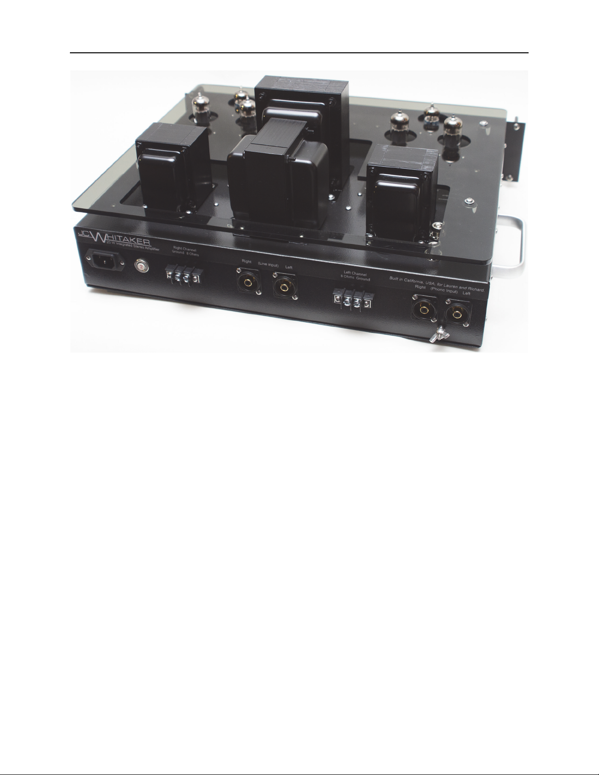
• Front panel switchable inputs (Phono, Line Input, Front Panel Aux)
• Front Aux input impedance 10 kΩ, 0.3 V rms nominal for full power output
• Line input impedance 10 kΩ, 1 V rms nominal for full power output
• Separate Bass and Treble tone controls provided
• Conservatively rated components used throughout
• Soft-start power supply to extend component life
• Adjustable output tube bias for optimal performance
• Automatic circuit protection built in, including auto-off feature
• Power requirements: 120 V ac, 60 Hz, 120 W nominal.
• Physical dimensions: 19-in wide by 16-in deep by 7-in high. Note that the depth
specification does not include back panel cables.
• Weight approximately 40 lbs.
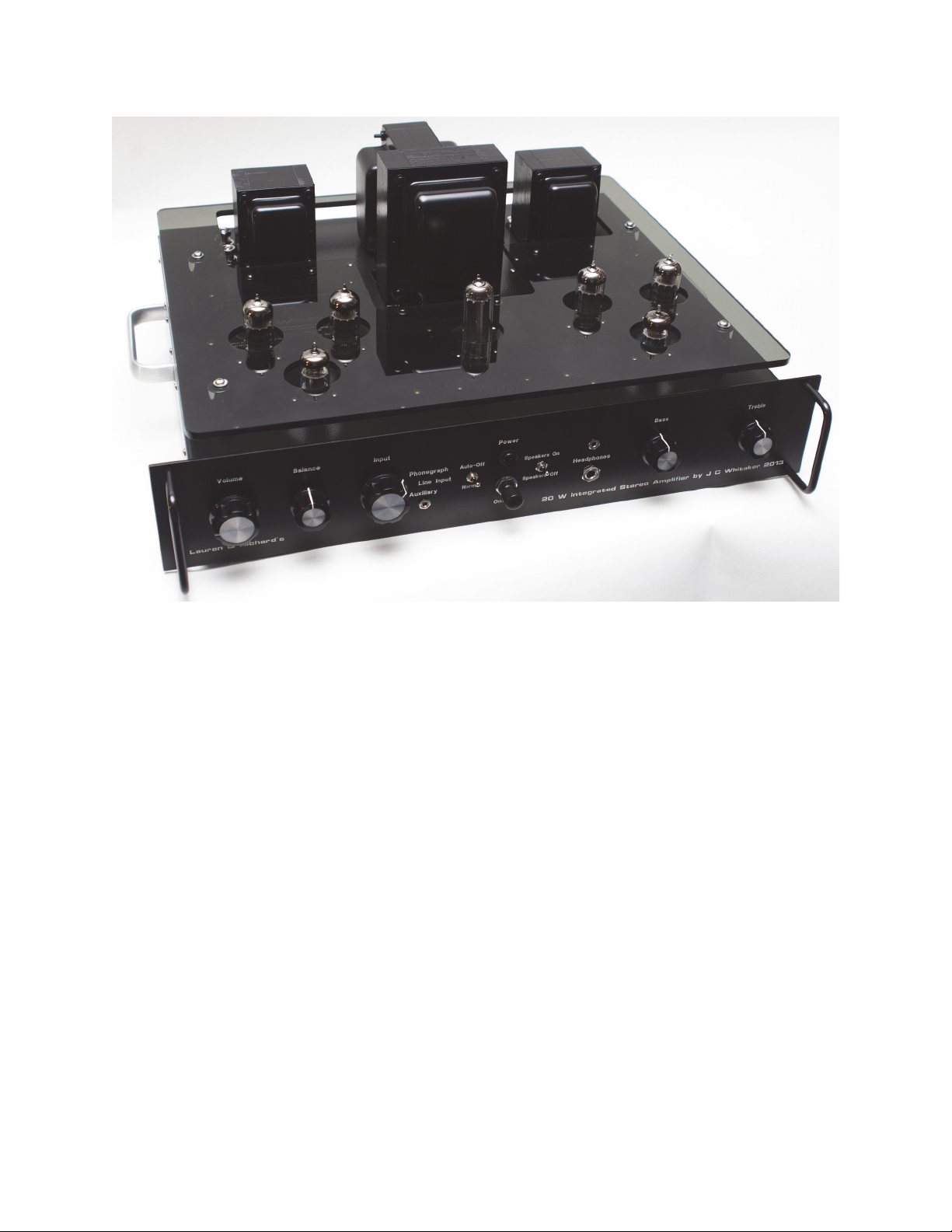
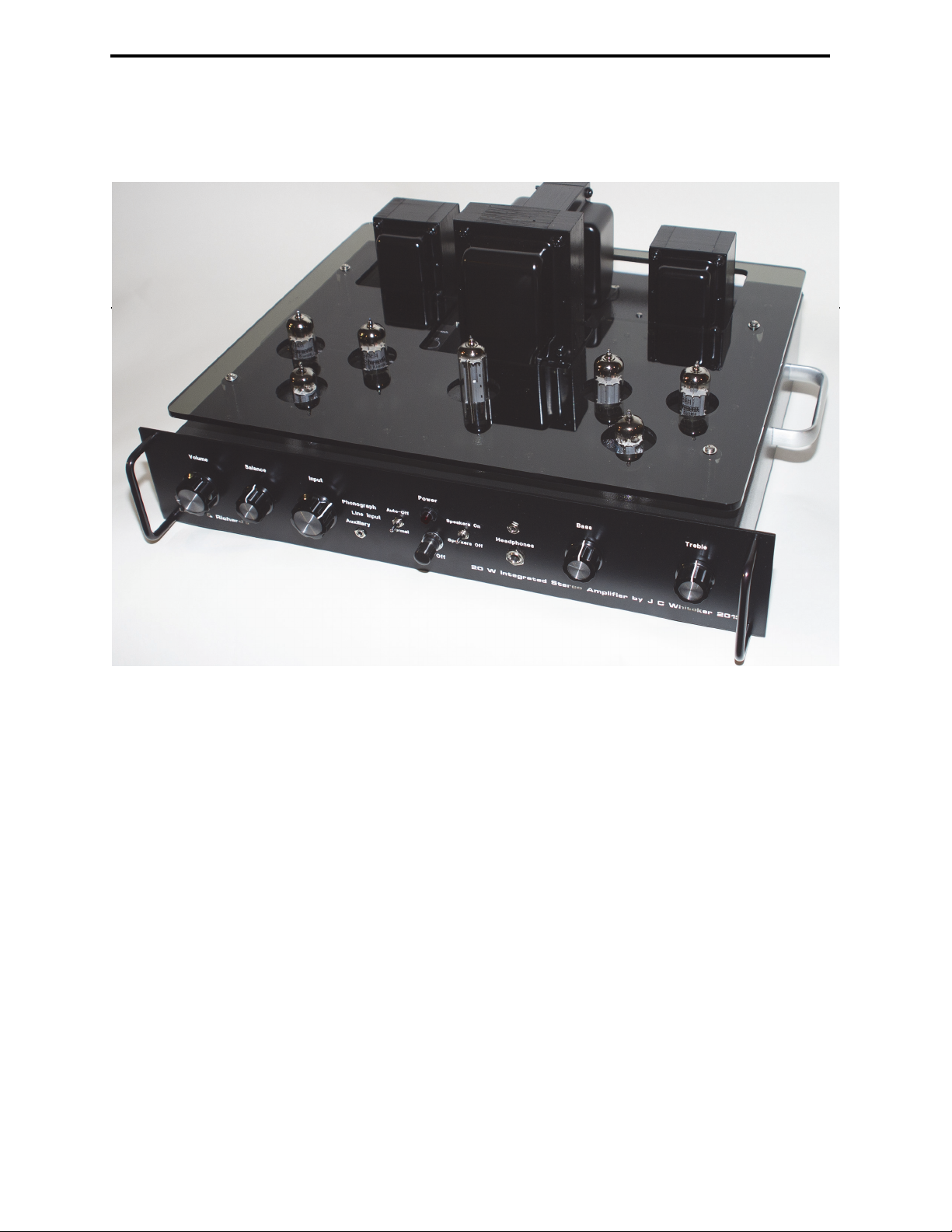
The amplifier is built around four main printed wiring boards (PWBs) and four special-
purpose boards, engineered for top performance. Component placement and board traces have
been engineered to minimize hum and noise. The boards feature a unique mounting technique for
the vacuum tubes that keeps heat away from the PWB and minimizes hum in the amplifier. The
PWBs are designed to reduce off-board connections, thereby simplifying layout and providing for
controlled characteristics from one unit to the next. The PWBs include top and bottom solder
masks and top-side silk-screened legends.
The power supply uses a vacuum tube rectifier feeding a choke and followed by a high-
capacity bank of filter capacitors.
The phonograph preamp and tone control circuits utilize discrete transistors. The circuits are
based on classic 1960s designs. This approach intends to maintain the tube-era sound, even for a
solid-state implementation. The benefits of transistors in this design include low noise and small
physical size.
The active circuits of the power amplifier utilize a 6U8A input amplifier and phase splitter.
The power output stage is built around a matched pair of 6973 beam power tubes. Top-quality

7
20 W Stereo Integrated Audio Amplifier
Hammond transformers are used throughout. The transformers are conservatively rated, providing
wide operating margins.
The output circuit utilizes a screen-tap configuration to optimize sonic performance. Generous
power supply filtering ensures a rock-steady reserve for the output stage.
Adjustable bias to the push-pull output tubes provides a wide range of operating points,
allowing users to find a good middle point between top performance and long tube life.
Beyond the great specs, the amplifier sounds very nice. Clean. Warm. Interesting. Like a tube
amp should sound.
The 20 W Stereo Integrated Amplifier is powerful enough to fill a room with great-sounding
music, and small enough to be practical for headphone listening. Aside from the obvious
application of this product in a home audio system, the 20 W Stereo Integrated Amplifier is ideal
for use in computer sound applications—for driving speakers or headphone listening (or both).
The amplifier generates little heat and (for a tube amplifier) consumes little power. Turn it on
and let it run. Put on some music and enjoy audio as it should be heard.
Rear view of the 20 W stereo integrated audio amplifier.

8
WhitakerAudio
Operational Note: Unplug the headphones when not in use. If left connected, the headphones
could be damaged by playing the amplifier at high volume using the speakers. Headphones
typically are not rated for high power operation.

9
20 W Stereo Integrated Audio Amplifier
1 Circuit Description
The 20 W Stereo Integrated Hybrid Amplifier is built around three main modules—the power
amplifier, preamplifier, and power management system. Each module is described in the
following sections.
1.1 20 W Stereo Amplifier Module
A schematic diagram of the 20 W stereo power amplifier and accompanying power supply is
shown in Figure 1.1. Note that power supply functions are generally divided between the right
and left channel boards as follows:
• Primary power distribution and control on the right channel board
• Power supply filtering on the left channel board
These functions are separated in order to maximize the available PWB real estate, and to keep ac
hum fields as far away as possible from the sensitive input circuits of the transistorized
preamplifier.
1.1.1 Amplifier Circuit
A high-gain pentode voltage amplifier is used as the input stage for the audio amplifier. The
output of this stage is direct-coupled to the control grid of a triode split-load type of phase
inverter. The use of direct coupling between these stages minimizes phase shift and,
consequently, increases the amount of inverse feedback that may be used without danger of low-
frequency instability.
A low-noise 6U8A tube (V1/ V4), which contains a high-gain pentode section and a medium-
µ triode section in one envelope, fulfills the active-component requirement for both the pentode
input stage and the triode phase inverter. A potentiometer in the tone control preamplifier
functions the volume control for the amplifier.
The plate and cathode outputs of the phase inverter, which are equal in amplitude and opposite
in phase, are used to drive a pair of pentode 6973 beam power tubes in a class AB1 push-pull
output stage (V2/V5 and V3/V6). The 6973 tubes are biased for class AB1 operation by the fixed
negative voltage applied to the control grid circuit from the power supply. Fixed bias is used
because a class AB amplifier provides highest efficiency and least distortion for this bias method.

10
WhitakerAudio
Figure 1.1 The 20 W amplifier: (a) amplifier PWB #1—right channel, (b, next page) amplifier
PWB #2—left channel.

11
20 W Stereo Integrated Audio Amplifier
Figure 1.1(b).

12
WhitakerAudio
Transformer T1/T2 couples the audio amplifier output to the speaker. Taps are provided on
the primary windings for connection to the screen grid of each output tube. This mode of
operation reduces distortion of the amplifier, albeit with a small power output penalty. The taps
on the secondary of the transformer match the plate-to-plate impedance of the output stage to the
speaker voice-coil impedance. Although the transformer specified provides output impedances of
4 Ω, 8 Ω, and 16 Ω, only the 8 Ω tap is provided at the back panel for connection to the
loudspeaker. Negative feedback of approximately 20 dB is coupled from the secondary of the
output transformer to the cathode of the input stage to reduce distortion and to improve circuit
stability. Use of taps other than 8 Ω can compromise the distortion performance of the amplifier
unless appropriate adjustments are made to the feedback circuit. For users requiring an output
impedance of something other than 8 Ω, a custom implementation can be provided.
For lowest distortion in a push-pull amplifier stage, it is important that the operating
parameters of the two output tubes are well matched. The first step in achieving high
performance, therefore, is the use of matched output tubes. These are readily available from a
number of vendors. The second step is to make certain that the components supporting the output
tubes are matched as well. To this end, resistors R6, R7, R9, R10, R11, and R12 for the right
channel and resistors R23, R24, R26, R27, R28, and R29 for the left channel are all 1% precision
devices. In addition, coupling capacitors C4 and C5 for the right channel and capacitors C10 and
C11 for the left channel are all 5% tolerance devices.
Two front-panel jacks are provided for connection of one or two headphones to the amplifier
for private listening. One jack is a conventional 1/4-inch stereo phone; the other is a miniature
(3.5 mm) stereo jack. For headphone listening, the speaker outputs would normally be turned off.
While this function could be accomplished with a simple switch, it would require bringing the
speaker output leads from the back of the chassis to the front panel and then back again to the rear
panel. To avoid the potential for feedback or noise that such an arrangement could set up, the
Speaker On/Off switch is fed from a +5 V dc source and used to control relays that are located
adjacent to the speaker terminals. For the condition where the speakers are switched off, an 8 Ω,
10 W load is placed across the output transformer secondary.
It should be noted that the front panel headphone jacks are wired across the output transformer
secondary windings. The headphones used must be wired for stereo operation. A mono plug will
short-circuit one of the output channels. Series resistors in the headphone circuit are provided to

13
20 W Stereo Integrated Audio Amplifier
prevent over-loading the transformer secondary winding if this happens. The performance of the
affected channel, however, will be compromised if a mono headphone phone plug is used.
Extended operation with one headphone channel shorted can result in component damage.
1.1.2 Power Supply
The transformer-coupled ac input power is converted to dc operating power for the amplifier
stages by the 6CA4 (V51) full-wave rectifier tube, the output of which is delivered to choke L51
and then to the filter bank. Filter capacitors for the B+ line are provided on both the right and left
channel amplifier boards.
The rated output voltage of the B+ power supply is 345 V dc. With the recommended bias
voltage on the grids of the push-pull output tubes (–30 V), the steady-state no-signal current draw
is 130 mA. When producing 10 W per channel (the rated output), peak current draw is 210 mA.
The maximum output of the power supply is 300 mA. The power transformer (T51) and choke
(L51) are conservatively rated for this application. The 6CA4 rectifier tube is rated for an average
output current of 180 mA; the rated peak current per plate is 500 mA.
Bias voltage has a significant impact on the steady-state current requirements of the amplifier
stages. An operating value of –30 V is strongly recommended. Lower (less negative) bias will
result in shorter tube life from the output devices and rectifier.
Fixed bias operation of the output stage requires that the power supply provide good voltage
regulation as the plate current of the 6973 tubes vary considerably with signal level. The
conventional choke-input type of power supply used provides the required stability. The fixed
bias for the output stage is obtained from a 50 V ac tap on the high voltage secondary winding of
power transformer T51. This voltage source is rectified by a silicon diode and filtered. A chassis-
mounted potentiometer (R57) is provided for adjustment of bias within a range of approximately
–20 V to – 50 V. Never set the operating bias on the output tubes for less than (more positive
than) –20 V dc. Component damage may result.
Potentiometer R55, connected across the 6.3 V secondary winding of transformer T51,
provides a hum balance adjustment for the amplifier. The wiper arm of the potentiometer is
connected to the junction of a resistive voltage divider across the output of the power supply. The
resulting positive voltage applied to the tube heaters minimizes heater-to-cathode leakage and

14
WhitakerAudio
substantially reduces hum. Zener diodes are provided in this circuit and the bias supply to prevent
excessive voltages due to component failure.
Power thermistor VR51 is included in the primary ac circuit to limit the inrush current when
power is first applied to the amplifier. When at room temperature, the resistance of VR51 is about
10 Ω but as it heats due to current through the device, the resistance drops to a fraction of an ohm.
Relay RYL51 takes VR51 out of the circuit after the amplifier has warmed up, thereby
eliminating a source of voltage drop in the primary circuit (and heat). The time delay for this
action is determined by a 5 V dc supply on the left channel PWB.
Filter FL51 conditions the input ac to remove noise present on the line. In addition, metal
oxide varistor (MOV) devices VR53 and VR54 suppress transient disturbances that could degrade
reliability of the system.
1.2 Transistorized Stereo Preamplifier Module
A schematic diagram of the preamplifier circuit is shown in Figure 1.2. Two PWBs a1re used.
The main board shown in Figure 1.2a contains the phono preamp, tone-control, and power supply
filter circuits. The daughter board shown in Figure 1.2b contains a buffer amplifier for the Front
Aux input.
The phono preamp is a three-stage high-gain circuit intended for use with a magnetic
phonograph pickup device. A nominal load of 47 kΩ is assumed for the phono cartridge. An input
signal of 0.0055 V rms at 1 kHz provides approximately 1 V output from the stage, which is 13
dB below the clipping point of the preamp and about 70 dB above the unweighted noise level. The
maximum output of the preamplifier is approximately 4.5 V rms, which is achieved with an input
level of 0.027 V rms at 1 kHz. At typical operating levels, THD is below 0.3 percent for the phono
preamp stage.
The equalized output of the phono amplifier stage is within 1 dB of the standard RIAA curve.
The equalization circuit includes C103/C104 and R107/R108 for the right channel and C107/
C108 and R117/R118 for the left channel. The output level of the preamplifier is matched to the
line and front panel auxiliary input levels through adjustment of R110 and R120.
All inputs (Phonograph, Line, and Auxiliary) are routed through front panel Input switch
SW101 to Balance control R121 and Volume control R122 before being applied to the tone
control circuit. The nominal input level from the preamplifier is 1 V rms for maximum output

15
20 W Stereo Integrated Audio Amplifier
Figure 1.2 Transistorized stereo preamplifier: (a) main PWB and chassis-mounted components,
(b, next page) daughter board PWB.

16
WhitakerAudio
Figure 1.2(b)

17
20 W Stereo Integrated Audio Amplifier
from the power amplifier. The Balance control provides a means to adjust for gain variations
between input source channels. A boost of about 2 dB and cut of infinity are available for each
channel at the extreme positions of the Balance control.
The tone-control amplifier uses a pair of NPN transistors connected through frequency-
sensitive (tone control) coupling networks in the feedback loop of the output stage.
The bass control in the coupling network can be adjusted to provide for up to approximately
12 dB of boost or attenuation (cut) at 20 Hz. The treble control has an adjustment range of
approximately 10 dB boost or cut at 20 kHz. With the bass and treble controls set at the mid-range
positions, the amplifier provides a flat response curve within approximately 1 dB from 7 Hz to a
remarkable 550 kHz1. The flat position for the bass and treble controls is at the approximate
center travel of each potentiometer. Owing to normal component tolerances, flat response may be
achieved slightly off-center for one or both potentiometers.
The clipping point of the tone control stage is approximately 3.0 V rms, which is achieved
with an input of 1 V rms at 1 kHz applied to the input terminals of the circuit (CONN103) with
the tone control potentiometers set for flat response. The nominal output operating level is 1 V
rms. At this level, THD is less than 0.3 percent; IMD is 0.01 percent or less. Noise is –75 dB or
better. Potentiometers R156 and R157 provide an adjustable output of the tone control circuit for
the right and left channels, respectively.
The Front Aux buffer amplifier (Q111/Q112) is essentially a duplicate of the tone-control
input stage (Q107/Q109). Because of the wide variety of personal entertainment devices currently
available, additional gain is provided beyond that typically achieved from the basic preamplifier
circuits. For an input of 0.3 V rms, the buffer amplifier delivers approximately 1 V rms to the
input selector switch, which is sufficient to drive the power amplifier section of the 20 W stereo
integrated amplifier to full output. At a typical operating level of 0.3 V rms input (1 V rms
output), frequency response is within 1 dB from 10 Hz to 50 kHz, THD is below 0.3 percent, IMD
is below 0.1 percent, and noise is –85 dB or better at the buffer amplifier output terminals
(CONN107).
1. This measurement was made on the bench in isolation. The overall performance of any audio system represents the concatena-
tion of the performance of the individual stages.

18
WhitakerAudio
The Front Aux buffer amplifier is typically set for a stage gain of approximately 3. Greater
sensitivity can be achieved by changing the ratio of R158 to R159 for the right channel and R165
to R166 for the left channel.
1.3 Power Management Module
The power management circuit board is a supervisory device that adds additional layers of
protection to the built-in protection already provided on the power amplifier. The power
management system adds the following features:
•Automatic Shutoff – While is possible to operate the amplifier continuously for long
periods of time, most consumers would likely prefer to not do so. Experience has shown
the amplifier may be tuned on to play one or more records and then inadvertently left on
after the record ends. Automatic Shutoff provides a fixed maximum run time for the
amplifier—adjustable to about two hours, +/– 15 minutes. This time delay can be defeated
at the option of the consumer.
•Over Temperature Shutdown – The amplifier is designed to operate reliably at normal
room temperature. If operated at an elevated temperature, component damage or
shortened tube life could result. This feature shuts down the amplifier if the temperature
inside the chassis exceeds 170°F. This is well below the maximum rated operating
temperature of the amplifier components.
•Under-Voltage Shutdown – The power supply is designed to operate reliably under a
wide range of conditions. It is possible, however, that because of the failure of a tube or
another component, the power supply could be loaded to the point that continued
operation could result in damage to one or more devices. This circuit monitors the plate
voltage supply at power-up and shuts down the amplifier if the B+ voltage is below
normal.
These protection mechanisms are in addition to the soft-start circuit and line voltage circuit
breaker already provided on the amplifier. The power management board also serves as a power
supply (+40 V dc) to the preamplifier board.
The power management PWB mounts inside the chassis near the rear panel. In keeping with
the 1960s era technologies of the 20 W Stereo Integrated Hybrid amplifier, the circuit design is
based on discrete transistor circuits.

19
20 W Stereo Integrated Audio Amplifier
Operation of the protection circuit is quite simple. If an out-of-tolerance condition is detected,
the amplifier will be shut off. To reapply power to the amplifier, push the front panel power
switch off and then on again.
For users who want the ability to defeat the auto-shutdown feature, a toggle switch is provided
on the front panel. This switch as two positions—Auto Off / Normal. A separate push-button may
optionally be installed to reset the time interval for the auto shutdown system, if desired.
A schematic diagram of the power management system is given in Figure 1.3. Relay-based
logic is used to latch power to the amplifier on and integrate the various protection mechanisms
into the control loop. The protection architecture will keep the amplifier in the off state until the
input ac power is cycled by operating the front panel power switch (off and then on) or by
unplugging and then reconnecting the ac power cord.
Varistors are included across the 120 V ac relays to eliminate transient disturbances. Diodes
are used across the coils of the 24 V dc relays to snub transient energy when the coil is de-
energized.
The time delay circuit consists of Q201 through Q203 and associated components2. The basic
circuit gives a time delay from a few seconds to several hours. With the circuit components
chosen for this implementation, a range of about two hours +/– 15 minutes can be selected
through setting of R209 (Delay Adjust). Clockwise rotation of R209 increases the delay time. The
timing interval is initiated by applying power to the circuit. At the end of the timing interval,
which is determined by the value of R201+R209 and C201, Q201 (2N494C) triggers a controlled
rectifier, Q203.
Charging resistor R201+R209 must be small enough to supply the minimum trigger current of
Q201 plus the leakage current of the capacitor when the emitter of the unijunction is biased at its
peak point voltage. This would place a limit on practical time delays of only 6 or so seconds. As
shown in the figure, a relaxation oscillator (Q202, 2N491) is included to reduce the minimum
trigger current requirement more than 1000 times by pulsing the upper base of Q202 with a 0.75
V pulse. The negative pulse causes the peak point voltage to drop slightly and if the voltage level
at C201 is greater than this, the unijunction will trigger. R202 is optimized for best stabilization
over the required temperature range. The maximum time delay that can be achieved by this circuit
2. The circuit description is adapted from: GE Transistor Manual, the General Electric Company, Syracuse, NY, 1964.

20
WhitakerAudio
Figure 1.3 Power management circuit for the 20 W integrated stereo amplifier.
Table of contents
Other WhitakerAudio Amplifier manuals
Popular Amplifier manuals by other brands

Audio Authority
Audio Authority CMX-144 Installation and operation

Channel Vision
Channel Vision A0360 instructions

NXP Semiconductors
NXP Semiconductors CGD944C Product data sheet

Alpine
Alpine MRP-M2000 - Amplifier owner's manual

Telefunken
Telefunken V 820 HiFi Bedienungsanleitung

Marantz
Marantz PM5003 Mode d'emploi

Yamaha
Yamaha A-U671 owner's manual

Lepai
Lepai LP-168HA user manual

Profile
Profile California Mosfet 400SX Installation and owner's manual

MFJ Enterprises
MFJ Enterprises MFJ-8802 instruction manual

Alpha Design Labs
Alpha Design Labs Esprit user manual

Fishman
Fishman ACOUSTIC MATRIX NATURAL I installation guide