WhitakerAudio 60 W Stereo Power Amplifier User manual

WhitakerAudio
60 W Stereo Power Amplifier
User and Assembly Manual

Copyright 2015 WhitakerAudio LLC, Morgan Hill, California, USA.
No part of this document may be reproduced without the express written consent of
WhitakerAudio.
Specifications subject to change without notice.
Any trademarks used in the manual are the property of their respective owners.
Note:
This document is intended to assist readers in building an audio product for personal use. No
warranties are expressed or implied. Always use good engineering practices and appropriate
safety precautions.

Table of Contents
1 Circuit Description 8
1.1 Power Supply 8
1.2 General Considerations 12
2 Parts List 15
3 PWB Design 21
4 Construction Techniques 27
5 Step-by-Step Instructions 29
5.1 Assembly of Right Channel PWB 30
5.2 Assembly of the Left Channel PWB 39
5.3 Assembly of the Power Supply PWB 46
5.4 Chassis and Final Assembly 52
5.4.1Front Panel Components 52
5.4.2Back Panel Components 54
5.4.3Cable Clamps and Related Hardware 56
5.4.4Install Choke 56
5.4.5Install Printed Wiring Boards 57
5.4.6Install Transformers 58
5.4.7Install Remaining Chassis Components 59
5.4.8Cable Organization 60
5.4.9Connect Transformer Leads 63
5.4.9.1 Right Channel Output Transformer Primary Leads 63
5.4.9.2 Left Channel Output Transformer Primary Leads 64
5.4.9.3 Choke Leads 65
5.4.9.4 Power Transformer Primary Winding Leads 65
5.4.9.5 Power Transformer Secondary Leads 66
5.4.10Primary Power Connections 68
5.4.11Chassis-Mounted Controls 72
5.4.12PWB Interconnections 74
5.4.13Audio Cabling 78
5.4.14 Speaker PWB Assembly and Installation 81
5.4.15Output Transformer Secondary Connections 85
5.5 Final Assembly Check 86
6 Initial Checkout 89
7 Performance Measurement 99
7.1 IMD Measurement 101
7.2 Hum Balance Adjustment 102
7.3 Clipping Point 102
7.4 Crosstalk 103
7.5 Square Wave Performance 104
7.6 Bias Adjustment 106
7.7 Drive Balance Adjustment 108
7.8 Recorded Performance 109

60 W Stereo Power Amplifier
The 60 W stereo audio amplifier is a high-quality device intended for high power output
requirements. The product features quality components throughout. The amplifier is available
either as a kit or assembled as a part of the signature series of products. This amplifier shares the
craftsmanship and impressive industrial design of the other offerings in the WhitakerAudio line.
This amplifier, like the other products, is limited in number.
Overview specifications:
• Tube amplifier providing high power output levels
• High-quality components and construction throughout
• Maximum of 30 W per channel peak output into 8 ohm load
• Sensitivity 0.92 V rms for full power output

6
WhitakerAudio
• Noise 90 dB below rated output (unweighted)
• Frequency response ±1 dB 10 Hz to 30 kHz at typical listening level (5 W)
• Harmonic distortion 0.7% or less at 5 W
• Intermodulation distortion 0.9% or less at 5 W
• Conservatively rated components used throughout
• Soft-start power supply to extend component life
• Adjustable output tube bias for optimal performance
• Power requirements: 120 V ac, 60 Hz, 170 W nominal.
• Physical dimensions: 19-in wide by 16-in deep by 8-in high. Note that the depth
specification does not include back panel cables. Weight approximately 47 lbs.
The amplifier is built around three main printed wiring boards (PWBs), engineered for top
performance. A ground plane covers the component side of the PWB. Component placement and
board traces have been engineered to minimize hum and noise. The boards feature a unique
mounting technique for the three vacuum tubes used in each channel that keeps heat away from
the PWB and minimizes hum in the amplifier.
The PWBs are engineered to reduce off-board connections, thereby simplifying layout and
providing for controlled characteristics from one unit to the next. The power supply uses a 5U4
rectifier tube feeding a choke and high-capacity bank of filter capacitors. The PWBs include top
and bottom solder masks and top-side silk-screened legends.
The active circuits utilize a 6U8A input amplifier and phase splitter. The power output stage is
built around a matched pair of 7027A beam power tubes. Top-quality Hammond transformers are
used exclusively. The transformers are conservatively rated, providing wide operating margins.
The output circuit utilizes a screen-tap configuration to optimize sonic performance. Generous
power supply filtering ensures a rock-steady reserve for the output stage.
Adjustable bias to the push-pull output tubes provides a wide range of operating points,
allowing users to find a good middle point between top performance and long tube life.
Beyond the great specs, the amplifier sounds very nice. Clean. Warm. Interesting. Like a tube
amp should sound.

7
60 W Stereo Power Amplifier

8
WhitakerAudio
1 Circuit Description
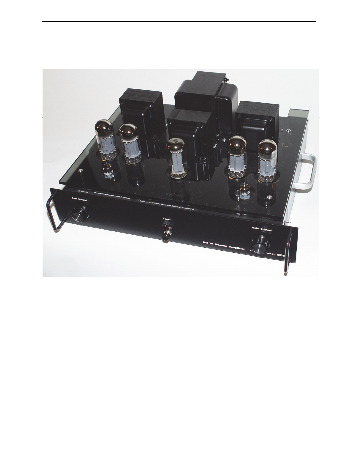
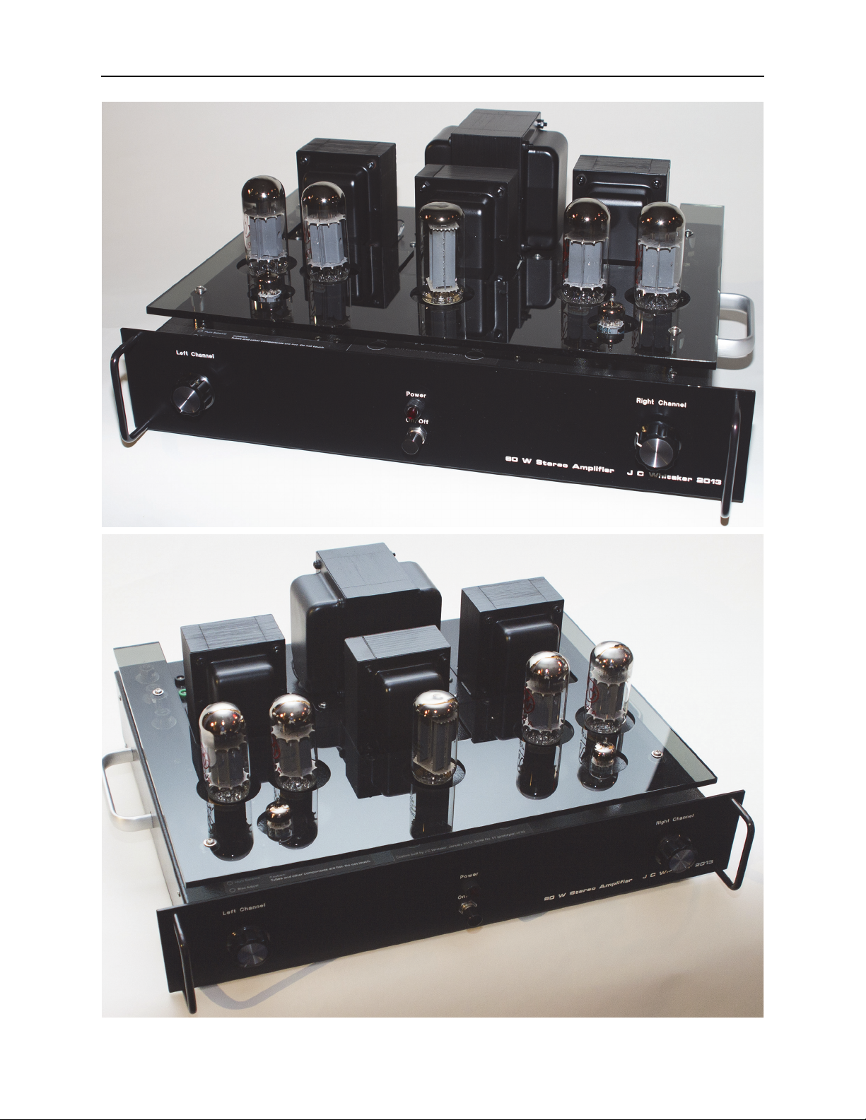
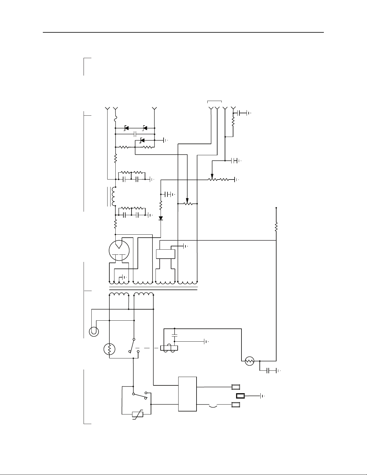
A schematic diagram of the 60 W stereo power amplifier is shown in Figure 1.1. The power
supply is shown in Figure 1.2.
A high-gain pentode voltage amplifier (V1) is used as the input stage for the audio power
amplifier. The output of this stage is direct-coupled to the control grid of a triode split-load type
phase inverter. The use of direct coupling between these stages minimizes phase shift and,
consequently, increases the amount of inverse feedback that may be used without danger of low-
frequency instability.
A low-noise 6U8A tube (V1), which contains a high-gain pentode section and a medium-µ
triode section in one envelope, fulfills the active-component requirement for both the pentode
input stage and the triode phase inverter. The potentiometer in the input circuit of the 6U8A
pentode section functions the volume control for the amplifier.
A linear taper potentiometer is specified for the volume control. A linear taper was chosen
over an audio taper under the assumption that the power amplifier will be fed by a preamplifier
with an integrated volume control. As such, the function of the volume control is only to set the
nominal input level of the amplifier and would not typically be adjusted during use.
The plate and cathode outputs of the phase inverter, which are equal in amplitude and opposite
in phase, are used to drive a pair of cathode-connected 7027A beam power tubes operating in a
class AB1 push-pull output stage (V2 and V3). Fine adjustment of drive balance is made with
potentiometer R20. The 7027A output tubes are biased for class AB1 operation by the fixed
negative voltage applied to the control grid circuit from the rectifier circuit. Fixed bias is used
because a class AB amplifier provides highest efficiency and least distortion for this bias method.
Transformer T1 couples the audio amplifier output to the speaker. The taps on the secondary
of the transformer match the plate-to-plate impedance of the output stage to the voice coil
impedance of an 8 Ω loudspeaker. Negative feedback of 18.5 dB is coupled from the secondary of
the output transformer to the cathode of the input stage to reduce distortion and to improve circuit
stability.
1.1 Power Supply
The use of an oversized power transformer and choke ensure ample energy for power output
stages. The transformer-coupled ac input power is converted to dc operating power for the

9
60 W Stereo Power Amplifier
Input
R19
Volume
control
R1
R3
R4
R5
R6
R7
R8
R9
R10
R11
R12
R13
R14
R15
C1
C2
C3
C4
C5
V1, 6U8A
V2, 7027A
V3, 7027A
+
+
+425 V
+425 V
+425 V
+55 V
+1.4 V
+130 V
+275 V
+125 V
–40 V
+425 V
3
1,4
5,6
8
2 7
5,6
8
2 7
1,4
3
45
61
9
8
3
2
7
R16 C6
16 Ohms
8 Ohms Speaker
outputs
T1
Ground
+425 V dc B+
–40 V dc bias
Ground
Heater
Heater
1
2
3, 4
5
6
6.3 V ac to
heaters
R17
R18
C7
+
C8
C9
4 Ohms
+400 V
R2
C10
Balance
R20
Preamp/Phase Splitter Power Amplifier Output Connections
Figure 1.1 One channel of the 60 W stereo power amplifier.
Figure 1.2 (next page) Power supply for the 60 W stereo power amplifier.

10
WhitakerAudio
120 V
T51
6.3 V ac to heaters
V51, 5U4
4
6
8
2
5 V, 3 A
L51
C54
C53
+
+
800 V ct.
288 mA
R53
R54
C51
Power supply output
C52
R51
R52
+
+
1, 2
3
5 V, 1.2 A
6.3 V, 6 A
5
6
R60
Hum Balance
50 V tap
D54 R59 C56
+
R61
Bias Adjust
C57
+
~20–60 V dc bias supply7
R62
VR51
SW51
Power
AC line
input
FL51
line filter
Hot Neutral
Ground
PL51
pilot lamp
RYL51 C59
VR52
CR51
ac
ac
+
–
+
R55
+
C58
Auxiliary supply output
4 Ground
+
C55
R56
R57
R58
D51
D52
D53
F51
VR53
+5 V source
R64
+ 540 V dc, no load
10 bias test point
C60
R65
CB51
Power Supply and Filter Output TerminalsInput Circuit

11
60 W Stereo Power Amplifier
amplifier stages by the 5U4 full-wave rectifier. The rectifier feeds a capacitor-input filter (C51/
C52) followed by choke L51 and a second capacitor bank (C53/C54). The maximum rated load of
the power supply is 288 mA, set by the rating of transformer T51 (Hammond 300BX).
Bleeder resistors (R51/R52 and R53/R54) are included across each filter capacitor to load the
supply and reduce the possibility of electrical shock during maintenance. The main filter capacitor
banks consist of two 100 µF 450 V electrolytic capacitors in series (effectively ~50 µF). Resistors
of 100 kΩ 2 W are placed in parallel with each capacitor to equalize the voltage distribution and
bleed off the charge when power is removed. The series filter capacitors were chosen over higher
voltage single devices because of cost benefits and layout simplicity.
As shown in Figure 1.2 an ac line input voltage of 120 V nominal is assumed. The primary of
plate transformer T1 can be connected to accommodate other voltages, including 110 V and 220/
240 V. In the case of 220/240 V, special considerations apply and are addressed on an individual
basis. Note that typical residential line voltages can vary widely. The construction steps contained
in this manual assume 120 V ac input. If lower line voltages are present, the amplifier may not
reach the full rated output power of 30 W per channel.
Power thermistor VR51 is used to limit current inrush upon application of ac line voltage to
the transformers. VR51 is rated for 8 A steady-state current. When “cold” (room temperature) the
device exhibits a resistance of 5 Ω; however, when loaded to 50 percent of rated current, the
resistance is just a fraction of an ohm. The benefit of having VR51 in the primary lead is found
only at power-up. During steady-state operation, the device performs no real purpose (other than
generating heat). Furthermore, the resistance of the device, while small, can impact the B+ supply
voltage under high power output due to the series resistance it adds to the primary circuit (0.5 V
drop across VR51 has been observed). For this reason, relay RYL51 is used to close the circuit
around VR51 after the power supply has reached its operating point. Power for RYL51 is derived
from one of the 5 V filament windings that are not otherwise used on the Hammond 300BX
transformer. The 5 V ac input is rectified by a bridge, filtered, and applied to RYL51 through
varistor VR52. Owing to the time constants involved, RLY51 typically closes about one minute
after power to the supply is switched on.
A varistor is included across the Power On/Off switch to minimize transient disturbance
resulting from removal of primary power from the amplifier. Switches normally exhibit some
amount of “contact bounce” when changed from one position to another. This can lead to noise

12
WhitakerAudio
resulting from the high voltages generated by the collapsing magnetic field of the transformers in
the circuit. The varistor is essentially invisible in the circuit until a predetermined voltage is
reached, at which point the resistance of the device decreases to a low value, thereby shunting the
transient energy. Attention to transient disturbances is critical for proper operation of solid-state
hardware; taking similar precautions in tube-based equipment is a good practice.
Heater power for the amplifier tubes and the rectifier are obtained from the 6.3 V and 5 V
secondary windings, respectively, on power transformer T51. Potentiometer R60 serves as a
“hum balance” control by placing a positive dc voltage on the heaters, derived from the output of
the power supply through a ladder divider, to minimize hum.
A grid bias supply of nominally –40 V is developed through a silicon rectifier and capacitor-
input filter connected to the bias supply winding of the plate transformer. A potentiometer at the
output of the supply (R61) is provided for fine adjustment of bias. Resistor R62 is included to
prevent adjustment of bias to a lower level that might be advisable for the amplifier. The range of
adjustment is in the neighborhood of –20 to –60 V dc. Test points are provided adjacent to R61 to
simplify bias adjustment.
Exercise caution when setting the bias. While a low setting may improve distortion
performance, it will also increase the idling current through the output tubes. If excessively high,
shortened tube life may result. It is recommended that the optimum bias point be identified and
then backed off (bias made more negative) by some amount (e.g., 5 V) in order to extend tube life
and reduce power consumption.
Since this power supply may draw a fair amount of current when working at high power
levels, it should be connected to a source of ac power that is capable of handling the load without
voltage sag due to loading or some other device on the circuit. The amplifier can certainly share a
15 A circuit with a preamp, tuner, phono turntable, and related devices. The unit should not share
an ac mains circuit with high-current loads such as heaters or other high-wattage appliances.
1.2 General Considerations
The 60 W stereo power amplifier chassis is somewhat cramped for space, but nonetheless quite
serviceable. The amplifier is also quite heavy. The handles included on each side of the chassis
are for more than just appearance. They are also necessary for moving the unit.

13
60 W Stereo Power Amplifier
The amplifier generates a considerable amount of heat from the seven tubes and plate
transformer. Normal convention cooling is adequate so long as airflow around the amplifier is not
restricted by other devices, shelving, etc.
Because of the large number of interconnecting wires needed for this amplifier, expanded
sleeving is used where practical to organize the cabling. This tends to simplify cable routing and
provided for a cleaner appearance.
The front panel of the amplifier is shown in Figure 1.3. The back panel is shown in Figure 1.4.
Figure 1.3 60 W stereo power amplifier front panel.

14
WhitakerAudio
Ground 8 Ohms 8 Ohms Ground
Circuit
Breaker AC Power
Left ChannelRight Channel Built in California, USA.
J C Whitaker 60 W Stereo Power Amplifier
Neutrix NF2D
0.88-in
0.13-in
Center
Neutrix NF2D
0.88-in
0.13-in
Center
AC connector shell
0.75-in x 1.08-in
Center 0.15-in
Molex 38720-3202 Molex 38720-3202
Figure 1.4 60 W stereo power amplifier rear panel.

15
60 W Stereo Power Amplifier
2 Parts List
A complete parts list for the 60 W stereo amplifier is given in Table 2.1. The table includes
manufacturer part numbers and stock numbers from one of the major parts houses1. These parts
are, of course, available from a number of manufactures and suppliers. The details given here are
for the convenience of the user. Substitutions of certain components may be made based on
availability.
1. Allied Electronics, 7151 Jack Newell Blvd. S., Fort Worth, Texas, 76118, USA,. www.alliedelec.com.
Table 2.1 Parts list for the 60 W Stereo Power Amplifier
Part Description Quantity Manufacturer Part No. Allied
Stock No.
C1 25 μF, 50 V,
electrolytic
2 Vishay TVA1306-E3 507-1089
C2 22 pF, 600 V, ceramic 2 Vishay 561R10TCCQ22 507-0880
C3, C7 180 μF, 450 V,
electrolytic
4 Cornell-Dubilier 381LQ181M450K022 862-4752
C4, C5 0.22 μF, 600 V 4 Vishay 715P22456MD3 507-0335
C6 0.015 μF, 200 V 2 Vishay 715P15352JD3 70079360
C6a 82 pF, 100 V (padding) 2 AVX SR151A820JAR 70195704
C8, C9, C60 0.01 μF disc, 1 kV 5 Vishay 562R5GAS10 507-0721
C10 0.01 μF, 100 V ceramic 2 Kemet C317C103K1R5TA 70095117
C51, C52,
C53, C54,
C55
100 μF, 450 V,
electrolytic
5 Cornell-Dubilier 380LX101M450J022 862-0144
C56, C57 22 μF, 100 V 2 Illinois Capacitor 226TTA100M 613-0352
C58, C59 1,000 μF, 25 V
electrolytic
2 Illinois Capacitor 108TTA025M 613-0327
R1 1 mΩ, 0.5 W 2 Ohmite OL1055E 70023092
R2, R65 10 kΩ, 0.5 W 3 Ohmite OL1035E 296-1483
R3 220 kΩ, 0.5 W 2 Ohmite OL2245E 296-4780
R4 825 Ω, 0.5 W 2 Vishay RN65D8250F 895-0098
R5 10 Ω, 0.5 W 2 Vishay RN65D10R0FB14 70200252
R6 182 kΩ, 0.5 W 2 Vishay RN65D1823F 895-0287
R7, R8 15 kΩ, 2 W 4 Ohmite OY153KE 296-2333
R9 470 Ω, 2 W 2 Ohmite ON4715E 70022967
R10 22 kΩ, 0.5 W 2 Ohmite OL2235E 296-4779
R11 2.2 kΩ, 2 W 2 Ohmite OY222KE 296-2343
R12, R13 100 kΩ, 0.5 W 4 Ohmite OL1045E 296-4773

16
WhitakerAudio
R14, R15 1 kΩ, 0.5 W 4 Ohmite OL1025E 296-4772
R16 200 Ω, 0.5 W 2 Vishay RN65D2000FB14 70200273
R17, R18,
R51, R52,
R53, R54
100 kΩ, 2W 8 Ohmite OY104KE 296-2322
R19 100 kΩpotentiometer 2 Honeywell/Clarostat 53C3100K 70153128
R20 2.5 kΩpotentiometer 2 Honeywell/Clarostat 53C22500 70153113
R55 10 Ω, 20 W 1 Ohmite B20J10RE 70022621
R56 12 kΩ, 5 W 1 Ohmite 25J12KE 70023223
R57 68 kΩ, 2 W 1 Ohmite OY683KE 70022237
R58 4.7 kΩ, 2 W 1 Ohmite OY472KE 70022230
R59 100 Ω, 2 W 1 Ohmite OY101KE 70022200
R60 100 Ω, 2 W,
potentiometer
1 Honeywell/Clarostat RV4LAYSA101A 70153091
R61 5 kΩ, 2 W
potentiometer
1 Honeywell/Clarostat RV4LAYSA502A 753-1145
R62 2.7 kΩ, 2W 1 Ohmite OY272KE 296-2349
R64 10 Ω, 1 Ω 1 Ohmite OX100KE 296-2246
RYL51 5 V dc relay, contacts
240 V ac, 30 A, SPDT
1 Magnecraft W9AS5D52-5 70184949
D51 Zener, 75 V, 5 W 1 ON Semiconductor 1N5374BG 568-0595
D52, D53 Zener diode, 200 V, 5
W
1 ON Semiconductor 1N5388BG Newark
D54 Rectifier, 2 A, 600 V 1 NTE 156 70214892
CR51 Bridge rectifier, 100 V,
2 A
1 NTE NTE166 935-6256
T1 Output transformer:
Primary–
6600 W plate-to-plate
40 W
Secondary–
4, 8, 16 W
2 Hammond 1650HA Newark1
T51 Power transformer:
Primary–
120 V
Secondary–
400-0-400 V rms, 288
mA
6.3 V, 5 A
5 V, 3 A
5 V, 1.2 A
1 Hammond 300BX Newark
Table 2.1 Parts list for the 60 W Stereo Power Amplifier

17
60 W Stereo Power Amplifier
L51 Choke:
5 H
300 mA
57 Ω
1 Hammond 193L Newark
V1 6U8A tube 2 JAN-Philips, GE,
others
Tube
Depot2
V2, V3 7027A tube 4 Electro-Harmonix,
others
Tube
Depot
V51 5U4 Tube 1 Electro-Harmonix Tube
Depot
VR51 Power thermistor, 5 Ω
cold
1 GE CL-40 837-0040
VR52 Thermistor, 20 Ωcold 1 Honeywell ICL1220002-01 254-0094
VR53 Varistor, 130 V ac 1 Littlefuse V07E130P 845-0587
Octal tube socket 5 Belton P-ST8-209MIP AES
9-pin tube socket 2 Belton P-ST9-601 AES3
1/2-inch #6 threaded
standoff
4 Keystone Electronics 2210 70181896
3/4-inch #4 threaded
standoff
26 Keystone Electronics 1895 839-0781
4 terminal barrier strip 3 Molex 38720-6204 607-0071
Main chassis, 14-in x
17-in x 3-in, steel
1 Hammond 1441-38BK3 806-1396
Main chassis
baseplate, 14-in x 17
in, steel
1 Hammond 1431-38BK3 806-1426
Front panel, 19-in x
3.5-in
1 Front Panel Express Custom
Front panel handles 2 RAF 8128-832-A 219-8007
Chassis feet 6 Bud F-7264-A 736-7264
Large knob 2 Davies 1110 543-1110
Handle, side 2 Bud H-9174-B 736-4374
RCA connector 2 Neutrik NF2D-B-0 514-0004
2 terminal speaker
barrier strip
2 Waldom Molex 38720-3202 70110957
SW51 Power switch, push-
button
1 NKK Switches WB12T-DA 870-0669
AC power connector 1 Schurter 6100.3300 70080620
4 terminal Molex
header
6 Molex 22-03-2041 863-0309
4 terminal Molex
housing
6 Molex 22-01-2041 863-0424
Molex crimp terminal 24 Molex 08-50-0114 863-0292
Table 2.1 Parts list for the 60 W Stereo Power Amplifier

18
WhitakerAudio
Consumables for the 60 W stereo amplifier are listed in Table 2.2.
Quick disconnect male 103 Keystone 4901 839-0344
Quick disconnect
female
103 3M FDI18-250Q 70233873
PL51 Pilot lamp housing 1 Dialight 508-8745-504 70081439
120 V ac pilot lamp 1 Dialight 507-4537-1431-640F 70082176
FL51 AC line filter 1 Qualtek 848-10/003 689-3564
CB51 Circuit breaker, 3 A 1 TE Connectivity W58-XB1A4A-3 70199433
AC power cord 1 Tripp Lite P006-006 70232541
F51 Fuse, 0.5 A, slo-blow 2 Littelfuse 0313.500HXP 845-0307
Fuse block 1 Bussman S-8002-1-R 740-0772
PWB, power supply 1 ExpressPCB Custom
PWB, amplifier blocks 2 ExpressPCB Custom
PWB, speaker
terminals
2 ExpressPCB Custom
Top chassis decal 1 FastSigns Custom
Rear panel overlay 1 FastSigns Custom
Banana jack, green 1 HH Smith 1509-104 70211155
Banana jack, black 1 HH Smith 1509-103 70211147
Notes:
1 Newark Electronics (www.newark.com).
2 Vacuum tubes are available from a number of suppliers, including: Tube Depot (www.tubedepot.com),
The Tube Store (www.thetubestore.com), Tube World (www.tubeworld.com), and other suppliers.
3 Antique Electronic Supply (www.tubesandmore.com/).
Table 2.1 Parts list for the 60 W Stereo Power Amplifier

19
60 W Stereo Power Amplifier
Table 2.2 Consumables for the 60 W Stereo Amplifier
Quantity Description
10 ft Hookup wire, #18 black, solid
10 ft Hookup wire, #18 green, solid
1 ft Hookup wire, #18 yellow, solid
10 ft Hookup wire, #22 black, solid
20 ft Hookup wire, #22 green, solid
10 ft Hookup wire, #22 white, solid
10 ft Hookup wire, #22 red, solid
5 ft Hookup wire, #22 red, solid, 600 V
10 ft Audio cable, 1 conductor shielded, stranded
5 ft Primary wire, #16 black, stranded
2 ft Primary wire, #16 white, stranded
5 ft Primary wire, #16 green, stranded
10 ft Expandable sleeving, small
10 ft Expandable sleeving, medium
1 ft Expandable sleeving, large
5 ft Heat-shrink tubing, small
5 ft Heat-shrink tubing, medium
2 ft Heat shrink tubing, large
12 Spade terminal, #6 screw, #22 wire
11 Quick-disconnect, male, 18 to 22 wire
2 Quick-disconnect, female, miniature, #22 wire
3 Ground lug terminal, #6 screw
40 Phillips head screw, #4, 3/8-inch
12 Nut, #4 with captive lock washer
24 Lock washer, #4
26 Phillips head screw, #6, 3/8-inch
5 Phillips head screw, #6, 1-inch
29 Nut, #6 with captive lock washer
1 Nut, #6, fiber locking
1 Wing nut, #6
22 Flat washer, #6
11 Lock washer, #6
4 Standoff, #6 female-female, aluminum
4 Sheet metal screw, Phillips head, #6
4 Standoff, chrome, 0.75-in. tall, 0.62-in. outside diameter, 0.32-in. inside diameter
8 Phillips head screw, #8, 3/8-inch
8 Lock washer, #8
5 Grommet, 0.5-in mounting hole

20
WhitakerAudio
2 Grommet, 0.75-in mounting hole
8 Cable clamp, 1/2-inch
8 Tie wrap, small
10 ft Rosin core solder
8 Vinyl pads, self adhesive
1 Paint, semigloss black hammered
1 Paint, black, satin
Table 2.2 Consumables for the 60 W Stereo Amplifier
Table of contents
Other WhitakerAudio Amplifier manuals