White Magic PRO 1900 User manual

WHITE MAGIC, INC.
PRO 1900
OWNER’S MANUAL
“OUR FUTURE DEPENDS ON YOUR COMPLETE
SATISFACTION.”
WHITE MAGIC, INC.
11 Main Street
Salisbury, MA. 01952
(800) 422-1128 03/29/2002
Revision 1.0
Price U.S. - $25.00


TABLE OF CONTENTS
Page#
1) ORIENTATION 3
2) INSTALLATION 4 -10
a) Tools Required 4
b) Placement of Major Components 5
c) Placing Machine into Van 6 - 8
d) Plumbing 9
e) Wiring 10
d) Fuel Line Hookup 11 - 12
e) Initial Start-up Procedure 16
3) OPERATING PROCEDURE 17 - 29
a) Vehicle Preparation 17
b) Standard Start-up procedure 17 - 19
c) Gauge Readings and Settings 21 - 23
d) Pulse Pump Priming 24
e) Chemical 24
f) Upholstery Cleaning 25
g) Pressure Washing 25
h) Water Extraction 25
i) Auxiliary Hot Water Output 26
j) Dual Wand Operation 26
k) Winterizing 27 - 28
l) Pumpout Winterization 29
4) MAINTENANCE 30 - 33
a) Daily 30
b) 25 Hours 31
c) First 50 Hours 31
d) 100 Hours 31 - 32
e) 200 Hours 32
f) 250 Hours 32
g) 400 Hours 33
h) 800 Hours 33
i) 1000 Hours 33
1

TABLE OF CONTENTS (continued)
Page#
j) 53 HP FORD MAINTENANCE 34 - 43
a) Operating Instructions 34 - 36
b) Maintenance Instructions 36 - 43
5) TROUBLESHOOTING GUIDE 44 - 48
a) Machine will not start when key is turned 44
b) Low Vacuum or Poor Air Flow 45
c) Water Pressure problems 46
d) Pulsation in the Pumping System 47
e) Low Water Temperatures 47 - 49
f) Poor Chemical Flow 50
6) DIAGRAMS
a) Vacuum Schematic
b) Pressure Schematic
c) Wiring Schematic
8) WARRANTY 51 - 52
2

ORIENTATION
The White Magic Pro 1900 is a 53 HP Ford liquid-cooled 4 cylinder pow-
ered carpet and upholstery cleaning system, completely self contained which re-
quires no external power or secondary fuels.
A large fresh water holding tank is provided with the Pro 1900 system. Hot
water is generated through a highly efficient heat transfer system. First the cool
water is heated in a pre-heater that transfers the heat from the hot engine coolant.
Next the water is superheated by means of the main heat exchanger that extracts
the heat from the hot exhaust gases of the engine. A catalytic converter has been
added for increased temperature and to reduce the pollution output associated with
combustion engines. The water temperature, water pressure, and amount of
chemical injection are completely adjustable.
The vacuum system is preset by the factory to provide the best extraction
and drying without exceeding the rating of the Roots 59 recovery blower. This
machine has dual wand capabilities and because of the high power it can be oper-
ated effectively at great distances. The pumping system runs cold water through it
to provide for the longest machine life possible. With proper maintenance this
machine is designed to provide years of efficient operation.
It is important to read this manual completely before using your White
Magic Pro 1900 System. It provides important operation, maintenance, and trou-
bleshooting information which if followed closely, will greatly increase the life of
your system.
•***NEVER , UNDER ANY CIRCUMSTANCES, MAY A PORTABLE CON-
TAINER BE USED OR CARRIED IN A VEHICLE EQUIPPED WITH
WHITE MAGIC EQUIPMENT. THIS PRACTICE IS UNSAFE AND IL-
LEGAL IN MOST AREAS. ONLY APPROVED EXTERNAL TANKS ARE
PERMITTED TO FUEL WHITE MAGIC EQUIPMENT.
3


INSTALLATION
READ THE ENTIRE INSTALLATION PROCEDURE CAREFULLY BEFORE
STARTING. THIS WILL ASSURE A CORRECT AND SAFE INSTALLATION.
TOOLS REQUIRED
The following is a list of tools needed to install the slide-in unit:
1. Fork Lift
2. Automotive jacks and several 24” long pieces of ½” diameter
black iron pipe
3. 2 pieces of 1 ¼” schedule 40 black iron pipe 42” long
4. Electric drill
5. Sawzall with metal cutting blades
6. Common hand tools (wrenches, hammers, etc.)
7. ¼”, 1 1/8”, 1 ½”, 1 ¾” & 3 ½” hole saws
8. Tube of silicone caulking
4

PLACEMENT OF MAJOR COMPONENTS
Diagram shows the approximate location of major components in a typical van in-
stallation.
36” Minimum
2 - 1/2”
CRITICAL
5

INSTALLING MACHINE INTO TRUCK
1. Remove the side covers from the machine. Place the two black iron
pipes through the ring lift points on the lower frame rail. Be sure to
clamp the pipes to the forklift as the machine is top heavy. Use these
pipes to lift the machine with a forklift and place in the truck.
2. The machine unit should be placed in the truck and jockeyed into
position prior to drilling of mounting holes for either section.
3. Situate the machine as close to the driver’s side wall as possible
without touching. Align the right hand side of the machine so it lies
even with the sliding door post and the driver’s side post. See
diagram under “Placement of major components.”
4. Prior to drilling the holes that bolt the machine to the floor, assure that
there are no components under the vehicle which will be damaged,
such as fuel lines, electrical wires or hydraulic lines.
5. Always use the supplied reinforcement brackets (J433) under the floor of van when
bolting the machine in place.
6. Once the machine is securely bolted in place, slide the 3" x 90
degree muffler sweep onto the blower pointing down. Mark the floor
approximately where the center of the sweep would go through the
floor, them remove sweep and drill with a 3-1/2" hole saw. Do the
same for the 1-1/2" sweep from the exhaust muffler and drill a 1-
¾" hole saw through the floor.
7. Clamp the 3" x 90 degree muffler sweep in place on the blower
output directed toward the new hole in the floor. From under the van
mount the other O3" x 90 degree muffler sweep to the first sweep.
Attach the muffler and hanger as shown in the diagram.
8. Clamp the 1-1/2" expanded muffler pipe to the 1-1/2" muffler
sweep and place through floor, then clamp in place to the muffler
output.
9. With a 1-1/8" hole saw drill a hole directly under the pop off
valve through the floor.
10. Run the pop off valve hose through the floor.
11. Seal all holes through the floor with high temp silicone caulking.
6

INSTALLING MACHINE INTO TRUCK (continued..)
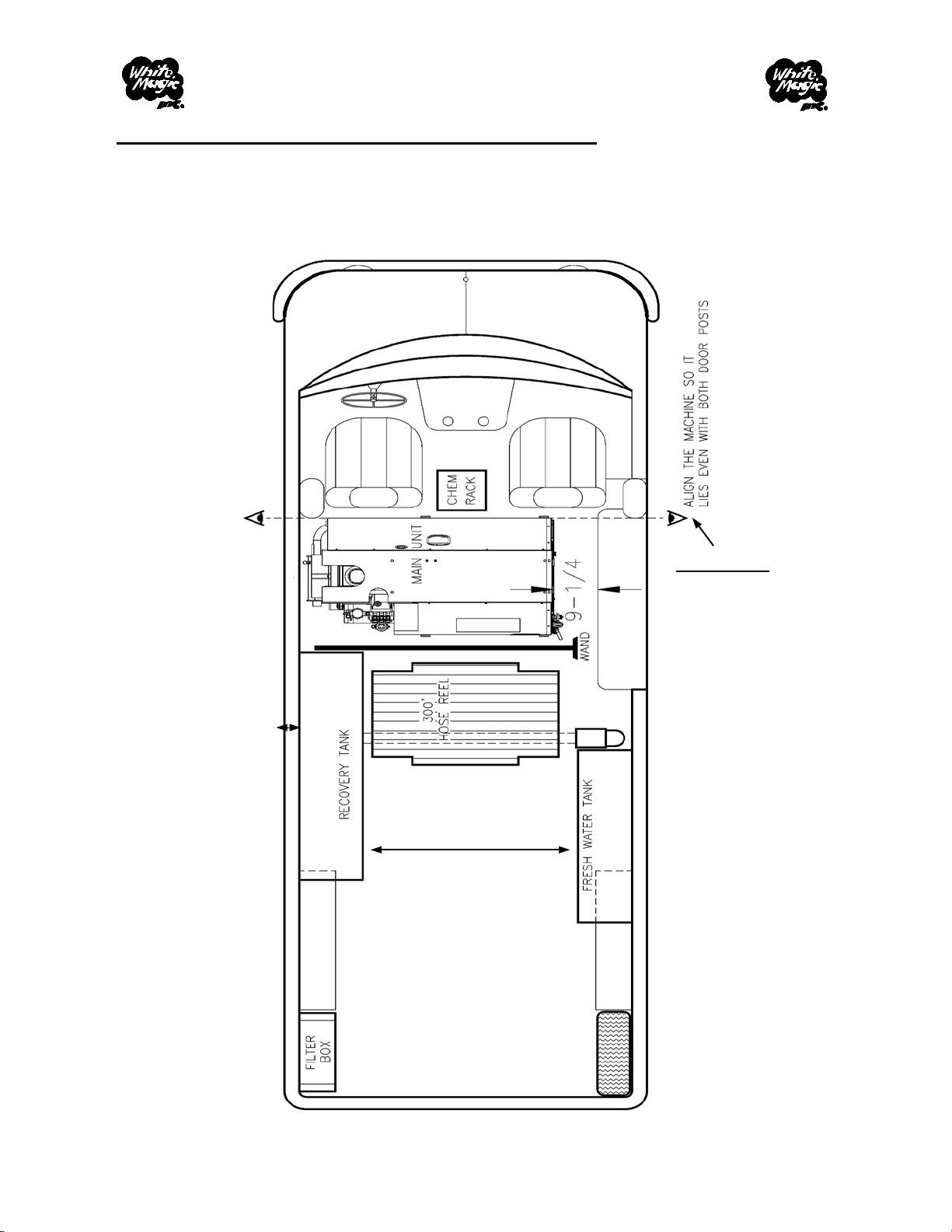
12. Recovery Tank must be placed as close to the drivers side of van as possible
(especially for hose reel clearance.) It should be placed 2 1/2” from the
side cover of the machine.
13. Drill a 7/16” hole 3” from either end of tank mounting foot. (Always check
to make sure no damage will be done to critical van components before
drilling any holes.) Drop a bolt in each hole as it is drilled to prevent the
tanks from moving. Drill through the mount on the top of the tank. Use a
1-1/2” long 3/8-16 fully threaded bolt, 3/8” flat washer, and a special 1” x 2
1/2” long nut plate supplied for the top. This can be slid into one of the
holes of the frame of the van and held with fingers while starting the bolt.
Use two 3/8-16 x 2” long fully threaded bolts with 3/8” flat washers for the
bottom of the tank. Use fender washers, lock washers, and nuts underneath
the van. It should be noted that where ever a bolt goes through the heat
shielding under the van a hole saw should be used to cut out some shielding
to give access for the hardware. Do not tighten the nuts against the heat
shielding.
14. Water tank must be as close to the passenger side of the van as possible.
Clearance between water and recovery tanks MUST be at least 36” to allow
for placement of hose reel. Front to back placement of water tank is flexible
and depends on van length, customer preference, and accessories such as;
water reels, sprayer racks, ect.
15. Secure water tank in same manner as recovery tank.
16. Install filter box if so equipped.
a.) The filter box is bolted to the floor with (3) 3/8-16 fully
threaded bolts with fender and lock washers underneath. It is positioned in
the rear driver’s side corner of the van with the 3” input toward the van
wall.
b.) A piece of 3” hose is cut to 7’ to go from the input of the recovery tank
to the output of the filter box. It should be tie strapped to the ribs of the van
wall approximately 40” from the floor.
17. Install hose reel if so equipped. Note that the hose reel must be tilted back
to check for clearance before bolting bracket to the floor. The side of the
hose reel should be even with the edge of the recovery tank.
7

Muffler Installation
Hanger may need modification.
8

PLUMBING
1. Run 1/2” water hose from pump to output valve on water tank. Note that the
hose is already connected to pump.
2. Run 1/2” bypass hose from unloader valve (already connected) to return
plumbing of water tank (slightly above output valve). Note that caution must
be used to not allow this hose to be kinked or pinched as it carries system pres-
sure when machine is running.
3. Drill a 1 1/8” hole through floor at the rear of the water tank for overflow hose.
Note that hose must be slit to insure pressure cannot build up in tank in case
hose gets blocked with ice , ect.
4. Connect 1/4” black vacuum hose from primer and pressure relief valves of ma-
chine to barb on recovery tank.
5. Connect 4” hose from blower input elbow to recovery tank filter assembly.
6. Run approximately 7’ of 3” hose from recovery tank to filter box if so
equipped. If no filter box, a 3” to 2” adapter is supplied to connect directly to
vacuum source.
7. Plumb 2” drain from recovery tank and clamp to floor. (Refer to Pro-1900
section pg. 6 G2)
8. Seal all holes through floor with silicone caulking.
***Drain location can vary according to vehicle type and size. Drawing is for
reference only.
9

WIRING
1. Install battery (note that battery is not included and must be Everstart #26 - 5
or equivalent) Obviously, use caution when hooking up battery.
2. Connect white wire from machine to brown wire of the recovery tank float
switch.
3. If equipped with an electric hose reel, run 10 Ga. Black wire from hose reel to
+terminal on the starter. Use a 14 Ga. fusible link in between. Ground hose
reel to left front mount bolt of hose reel with existing ground wire terminal.
Note that machine recovery tank and hose reel must have common ground if
mounted to a wooden floor.
10

Do not start vehicle or use any electrical devices that could accidentally ignite
gasoline while installing any of the connections into the fuel tank. Use an indus-
trial knife to cut hoses.
1. Assume that gasoline level in the vehicle’s fuel tank is below the
level of filler connection to the tank. If it is not below this level it
will be necessary to drain out some of the fuel.
2. Cut 2" fuel filler hose in two pieces 4"- 6" above the fuel tank con-
nection. Install the stainless steel adapter into the hose feeding the
¼"stainless steel braided hose down into the fuel tank. Ensure that
the hose is long enough to reach the tank bottom. Secure adapter
connections tightly with stainless steel hose clamps.
3. Drill a ¾" hole in the floor between the battery tray and preheater to
run the fuel line from the Ford engine fuel pump to the fuel line
adapter. Use a short piece of ½" hose to protect the fuel line where it
passes through the floor. Silicone around the hose. Use stainless
steel hose clamps to tightly secure the ends of the fuel line on the
fuel pump and adapter.
4. Make sure that the fuel line is not routed near the vehicle’s or ma-
chine’s exhaust system or near any moving parts. Secure the fuel
line to the vehicle body and/or frame with appropriate clamps or tie-
wrap straps.
5. Adjust the lengths of any of the hoses as necessary.
FUEL LINE HOOKUP
11

12

13
2003 Chevy
Fuel Line Kit Installation Procedure
07-01-03
1.) Install White Magic Inc.’s
Signature Series machine us-
ing installation procedure and
assure all safety precautions
have been taken. If the bat-
tery has already been in-
stalled, remove and relocate
battery away from area.
2.) *Using extreme caution
as the van’s gas tank is in
close proximity, drill a 7/8”
hole through the floor of the
van near the rear left corner of
the machine. (Fig. 1)
3.) Mount (PN#J545) bracket
to floor of van using (2)
(PN#D028) Tek Screws. The
bracket may be mounted
across the floor slots as shown
or in them. (Fig. 2)
4.) Run the fuel line through
the (PN#A020) grommet and
bracket then out of the floor of
the truck. Use silicone spray
to move grommet over hose
more easily. (Fig. 2)
Fig. 1
Fig. 2
***IMPORTANT***
As of 09/09/03 the fuel line kit (PN#A500) can be used only with a White Magic Signa-
ture Series machine (on machines manufactured after 07-01-03, w/ S/N# 237066 and
above.) A special fuel solenoid is required in conjunction with this kit to prevent dan-
gerous fuel spills or leaks. Currently, White Magic Signature Series Machines utilize
these solenoids. In the future, all White Magic Slide-In Systems will be fitted with these
solenoids. However, the factory should be consulted if the machine being installed was
shipped without a (PN#A500) fuel line kit as original equipment.

2003 Chevy
Fuel Line Kit Installation Procedure
07-01-03 5.) Loosen or remove
this clamp to allow for
more working room.
6.) Using a good quality
mini pipe cutter (such as
“Rigid”), cut into the
metal return line as
shown. (Fig. 3)
***NEVER, UNDER
ANY CIRCUM-
STANCES, USE ANY
ELECTRICAL DEVICE
OR OTHER DEVICE
THAT MAY CAUSE A
SPARK TO CUT THE
FUEL LINE, OR TO
PERFORM ANY TASK
IN THE VECINITY OF
ANY MOTOR FUEL.***
Approx. 1”
Fig. 3
Approx. 1”
Fig. 4
Gas Flow
**The return line is the
5/16” diameter tube con-
nected to one of the two
flexible lines.
(Fig. 4)
***The 3/8” line is the
main feed from the fuel
pump. DO NOT cut this
line. (Fig. 4)
Be sure to measure hose
diameter prior to each
installation.
14

2003 Chevy
Fuel Line Kit Installation Procedure
07-01-03 6.) Install the
(PN#B192) Compres-
sion Tee and the
(PN#E090) 1/4” barb
X 1/4” FPT .
If this hose has a ten-
dency to kink, it may
be necessary to remove
a small section of tube.
(See Fig. 3, 4)
Tighten the compres-
sion nuts with barb
pointing upward.
(Fig. 5)
6.) Route the fuel line
to the barb and secure
using a (PN#B029)
1/4” SS hose clamp.
Also re-tighten the
clamp holding the fuel
lines.
Fig. 5
Fig. 6
7.) Carefully check for
leaks by running van
engine for a few min-
utes.
NOTE: NEVER run
your carpet cleaning
machine with van en-
gine running.
8.) Turn machine on to
assure good gas flow.
15

INITIAL START-UP & TEST RUN
WARNING: Do not attempt to start and/or run the machine until the machine in-
stallation is completed and this manual has been entirely read and fully under-
stood.
1. Fill the water tank with clean fresh water.
2. Fill the chemical jug and place the chemical line in the jug.
3. Attach the hose and the standard wand to the machine.
4. Set the temperature on the control knob to about ¾ of the way to HI.
5. Flip the Machine Mode switch on the machine to “Normal”.
6. Flip the Pump power switch to the “on” position.
7. Assure that the temperature control valve is in the closed position.
8. Assure that the manual pressure relief valve on the lower manifold is
closed.
9. Start the engine and run at a low speed. ( Refer to “Machine set-up
for carpet cleaning operation” steps 1-15
10. Attach a hose to the Auxiliary valve then open until a good steady
flow is observed from hose then close.
11. Key the wand until it produces a steady spray then adjust the pres-
sure with the pressure adjust knob to 500 psi.
12. Seal the vacuum at the wand, reel, and tank. Turn the chemical
switch to “PRIME” until all air is purged from the chemical lines and
flow meter, then return to “ON”
13. Adjust the chemical flow with the chemical adjust knob using a
White Magic standard wand.
14. Set the engine RPM to approximately 2500 RPM and turn the tem-
perature to the maximum setting.
Without using any water the temperature will cycle. First at a low temperature
then going higher each cycle until the engine has reached it's optimum operating
temperature. This is the point when the thermostat open (the upper radiator hose
gets hot to the touch). Temperatures should cycle between 260 degrees max and
230 degrees min.
16

Table of contents