KOLO BOLLARD
Whitecroft Lighting Limited
Electrostatic
Sensitive Device
High Voltagle
LED's
Whitecroft Lighting Limited
Electrostatic
Sensitive Device
High Voltagle
LED's
KOLO BOLLARD
A
B
C
D
E
F
G
H
I
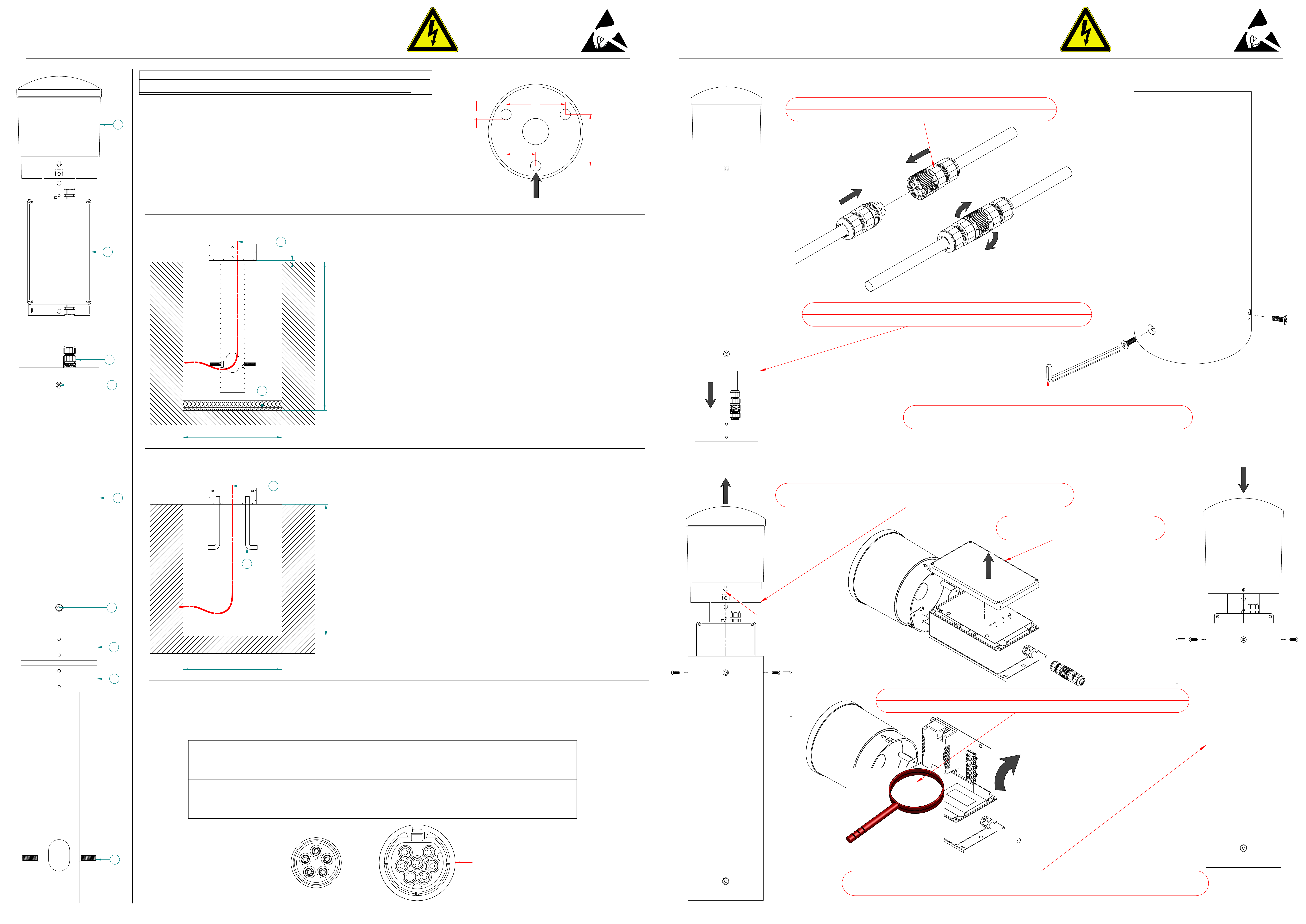
ROOT MOUNT INSTALLATION.
450
Dig a hole at least 300 X 300 X 450mm deep. A gravel layer (J) at the bottom
is recommended for better drainage.
Remove root mount (H) from body (E), via 3 x M6 screws (F).
Attach provided nut and bolt (I) to root mount (H). (Stored inside body (E) )
Feed armoured cable (K) through cut out in root mount (H). Ensure there is
enough cable for wiring to the bollard. (Approx. 100mm above ground level.)
Support the root mount so a 5mm gap can be achieved from ground level as
shown. This will ensure the bollard will connect properly when the concrete has
set.
Fill the hole with concrete. DO NOT USE QUICK SETTING CONCRETE.
Make sure the root mount (H) tube fills with concrete.
Check the bollard can be attached to the root mount, before allowing the
concrete to set.
o
o
o
o
o
o
o
K
J
5
FLANGE MOUNT INSTALLATION.
K
L
Dig a hole so that the bollard is adequately supported. (Suggested 300 X 300
X 400mm minimum.)
Ensure there is enough armoured cable (K) for wiring to the bollard. (Approx.
100mm above ground level.)
Fill the hole with concrete. DO NOT USE QUICK SETTING CONCRETE.
Fit J-bolts into concrete, use flange mount plate (G) as a guide.
(Recommended size M12 x 150mm)
Remove flange mount plate (G) from the body (E), via 3 x M6 screws (D)
Feed armoured cable through central hole on flange mount plate (G).
Flange mount plate (G) should be attached using 'J-bolts' (L), Rawl bolts can
also be used. Recommended size is M12 x 150mm. (Not Supplied)
o
o
o
o
o
o
o
400
REMOVE ALL PACKAGING AND ENSURE THERE IS NO DAMAGE TO THE PRODUCT.
REPLACE PACKAGING WHILST INSTALLING TO PREVENT CAUSING DAMAGE.
IMPORTANT ORIENTATION INFORMATION.
IT IS IMPORTANT THAT THE ROOT/FLANGE MOUNT ARE CORRECTLY
POSITIONED WHEN INSTALLED. POSITION 1 OF THE 3 FIXING POINTS
TO WHERE THE FRONT OF THE PRODUCT SHOULD BE. SEE DIAGRAM
TO THE RIGHT.
FRONT
WIRING INFORMATION.
EMERGENCY VERSION- BATTERY CONNECTION.
BOLLARD ASSEMBLY.
STEP 1
CONNECT BOLLARD PLUG TO NEWLY WIRED MAINS END PLUG.
Bollard supplied with male and female IP plug. Male end is wired to the product. Female end is to be wired to the
armoured cable.
o
STEP 2
SLIDE BOLLARD ON FLANGE/ROOT MOUNT BASE AND ALIGN HOLES
STEP 3
SCREW BODY TO BASE WITH 3 X SCREWS (F) USING 4MM HEX TOOL
STEP 4
REMOVE HEAD ASSEMBLY VIA 3 SCREWS (D) USING 2.5MM HEX TOOL
ARROW MARKS FRONT
OF PRODUCT
STEP 5
REMOVE IP BOX (B) LID. 4 X SCREWS.
STEP 7
RE-ATTACH HEAD ASSEMBLY TO BODY. TIGHTEN SCREWS EVENLY.(2-3NM TORQUE)
STEP 6
FOLD OUT GEARTRAY TO ACCESS BATTERY CONNECTIONS AND CONNECT.
300
300
Connection (5 core plug) Cable section: 5 core-0.5mm² to 1.5mm² (6mm strip length)
Terminals (5 core plug) 1,2 (DALI) 3 (LIVE) 4 (EARTH) 5 (NEUTRAL)
Connection (6 core plug) Cable section: 6 core-0.2mm² to 2.5mm² (8mm strip length)
Terminals (6 core plug) 1,2 (DALI) L (LIVE) N (NEUTRAL) Ls (SWITCHED LIVE)
O
16
90
78
45
TORX6-KEY REQUIRED FOR PLUG.
(TORX T6 SCREW HEAD)
DO NOT APPLY
EXCESSIVE TWISTING
FORCE TO BOLLARD
HEAD.
DO NOT APPLY
EXCESSIVE TWISTING
FORCE TO BOLLARD
HEAD.


