Wieland SNO 4083KM User manual

Betriebsanleitung
(Original-Betriebsanleitung)
SNO 4083KM
Wieland Electric GmbH
Brennerstraße 10-14
D-96052 Bamberg
Tel. +49 (0) 951 / 9324 -0
Fax +49 (0) 951 / 9324 -198
www.wieland-electric.com
Doc. # BA000773 – 11/2014 (Rev. H) SNO 4083KM DE 1
Basisgerät für Not-Aus- und Schutztür-Anwendungen
•Basisgerät nach EN 60204-1:2007 und EN ISO 13849-1:2007 für ein- oder zweikana-
lige Not-Aus-Überwachung.
•PL e / Kategorie 4 nach EN ISO 13849-1:2007
•SILCL 3 nach DIN EN 62061:2005
•Stop-Kategorie 0 gemäß EN 60204-1
•Manueller oder automatischer Start
•Mit / ohne Querschlusserkennung
•Rückführkreis zur Überwachung externer Schütze
•Drei Freigabestrompfade, ein Meldestrompfad
•Auswerteeinheit für BWS Typ 4 gemäß EN 61496-1
•Einsatz nach EN 81-1 und EN 50156-1
•Zur Nachschaltung an eine Schaltmatte gemäß EN 1760-1
Geräteausführungen
SNO 4083KM-A DC 24 V mit Schraubklemmen, steckbar
SNO 4083KM-A AC 115-230 V mit Schraubklemmen, steckbar
SNO 4083KM-C DC 24 V mit Federkraftklemmen, steckbar
SNO 4083KM-C AC 115-230 V mit Federkraftklemmen, steckbar
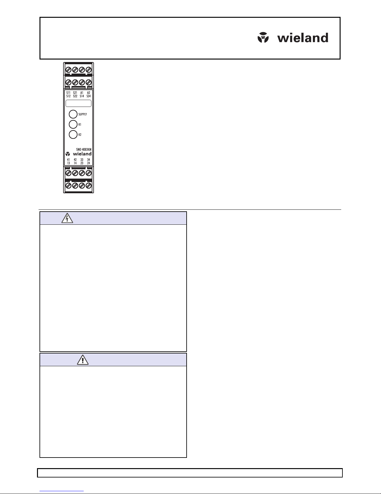
Frontansicht
Supply LED grün Betriebsspannungsanzeige
K1, K2 LED grün Betriebs- und Statusanzeige der Relais K1, K2 und der
Sicherheitskreise
SICHERHEITSBESTIMMUNGEN
•
Die Montage, Inbetriebnahme, Änderung und Nachrüstung
darf nur von einer Elektrofachkraft ausgeführt werden!
•Schalten Sie das Gerät / die Anlage vor Beginn der Arbeiten
spannungsfrei! Bei Installations- und Anlagenfehlern kann
bei nicht galvanisch getrennten Geräten auf dem Steuer-
kreis Netzpotential anliegen!
•Beachten Sie für die Installation der Geräte die Sicherheits-
vorschriften der Elektrotechnik und der Berufsgenossen-
schaft.
•Durch Öffnen des Gehäuses oder sonstige Manipulation
erlischt jegliche Gewährleistung.
•Bei unsachgemäßen Gebrauch oder nicht bestimmungsge-
mäßer Verwendung darf das Gerät nicht mehr verwendet
werden und es erlischt jeglicher Gewährleistungsanspruch.
Nicht zulässige Einwirkungen können sein: starke mechani-
sche Belastung des Gerätes, wie sie z.B. beim Herunterfal-
len auftritt, Spannungen, Ströme, Temperaturen, Feuchtig-
keit außerhalb der Spezifikation.
•Bitte überprüfen Sie gemäß der geltenden Vorschriften bei
Erstinbetriebnahme Ihrer Maschine / Anlage immer alle
Sicherheitsfunktionen und beachten Sie die vorgegebenen
Prüfzyklen für Sicherheitseinrichtungen.
WARNUNG
•
Führen Sie vor Beginn der Installation/ Montage oder
Demontage folgende Sicherheitsmaßnahmen durch:
1. Schalten Sie das Gerät / die Anlage vor Beginn der Arbei-
ten spannungsfrei!
2. Sichern Sie die Maschine / Anlage gegen Wiederein-
schalten!
3. Stellen Sie die Spannungsfreiheit fest!
4. Erden Sie die Phasen und schließen Sie diese kurz!
5. Decken und schranken Sie benachbarte, unter Spannung
stehende Teile ab!
6.
Der Einbau der Geräte muss in einem Schaltschrank mit
einer Schutzart von mindestens IP54 erfolgen.
•Eingeschränkter Berührungsschutz!
-Schutzart nach EN 60529: IP 20.
-Fingersicher nach EN 50274.
1Bestimmungsgemäße Verwendung
Die Geräte sind Sicherheits-Schaltgeräte. Sie dürfen nur als Teil
von Schutzeinrichtungen an Maschinen zum Zweck des Perso-
nen-, Material-, Funktions- und Maschinenschutzes eingesetzt
werden.
2Funktion
Das Gerät ist ein zweikanaliges, bei jedem EIN-AUS-Zyklus sich
selbst überwachendes Sicherheitsschaltgerät für Not-Aus-Ein-
richtungen nach EN 60204-1, welches mit zwangsgeführten
Relais ausgestattet ist. Das Gerät ist zur Nachschaltung an
kurzschlussbildenden Schaltmatten, Schaltleisten oder Schalt-
kanten in 4-Leiter-Technik (ohne Überwachungswiderstand)
geeignet.
Grundfunktion: Nach Anlegen der Versorgungsspannung an
die Klemmen A1 / A2 und geschlossenen Sicherheitseingängen
werden bei einem gültigen Resetsignal an S34 die Freigabe-
strompfade geschlossen. Beim Öffnen / Entregen der Sicher-
heitseingänge werden die Freigabestrompfade geöffnet.
Betriebsarten / Systemfunktionen
•Ein- oder zweikanalige Ansteuerung
•Mit oder ohne Querschlusserkennung
•Manueller Start (Triggerung mit fallender Flanke)
•Automatischer Start
•Auswertung äquivalent oder antivalent schaltender Signalge-
ber
Doc. # BA000773 – 11/2014 (Rev. H) SNO 4083KM DE 2
HINWEISE
•
Der Performance Level (PL) sowie die Sicherheits-Kategorie
nach EN ISO 13849-1 hängt von der Außenbeschaltung,
dem Einsatzfall, der Wahl der Befehlsgeber und deren örtli-
cher Anordnung an der Maschine ab.
•Der Anwender muss eine Risikobeurteilung nach
ISO 14121-1 durchführen.
•
Auf dieser Basis muss eine Validierung der Gesamtanlage /
-maschine nach den einschlägigen Normen durchgeführt
werden.
•
Der angegebene Performance-Level wird nur erreicht, wenn
je nach vorliegender Belastung des Gerätes (vergl. EN ISO
13849-1, Tab. C.1) und dem Anwendungsfall eine mittlere
Anzahl von Schaltzyklen pro Jahr nicht überschritten wird
(vergl. EN ISO 13849-1, C.2.3 und Tab. K.1). Mit einem
angenommenen B10d-Wert von 400.000 Schaltzyklen für
eine maximale Last ergibt sich z.B. eine maximale Zyklen-
zahl von 400.000 / (0,1 × 30) = 133.333 Schaltzyklen pro Jahr.
•
Die sicherheitstechnischen Kenngrößen gelten nur, wenn
die Relais mindestens einmal im Jahr geschaltet werden.
•
Das Betreiben des Gerätes außerhalb der Spezifikation kann
zu Funktionsstörungen oder zur Zerstörung des Gerätes
führen.
•
Vor der Inbetriebnahme, nach dem Austausch von Modulen
und / oder Änderungen an einer abgenommenen Installation
ist eine Überprüfung der ordnungsgemäßen Funktion
durchzuführen.
•
Bei Betrieb mit 115–230 V AC sind die Betriebsmittel der
Steuerkreise für eine Bemessungsspannung von 300 V
auszulegen. Basisisolierung zwischen Versorgungs- und
Steuerkreise.
•
Grundsätzlich sind beim Betrieb des Gerätes die angegebe-
nen Zeiten einzuhalten, ansonsten kann es zur Verriegelung
des Gerätes kommen. Die Verriegelung kann durch ord-
nungsgemäßes Öffnen der Sicherheitseingänge aufgehoben
werden.
HINWEISE
•
Zur Vervielfältigung der Freigabestrompfade können die
Erweiterungsgeräte der Reihe SNE oder externe Schütze
mit zwangsgeführten Kontakten eingesetzt werden.
•Die Kontakte müssen mit maximal 6 A Betriebsklasse gG
abgesichert werden.
•
Die Steuerausgänge S11 und S21 sind mit einem Überlast-
schutz (bei Kurzschluss) ausgerüstet. Nach Beseitigung der
Störungsursache ist das Gerät nach ca. 3 s wieder betriebs-
bereit.
•
Die Steuerein- und ausgänge dienen ausschließlich dem
Anschluss von Befehlsgebern und nicht dem Anschluss
externer Verbraucher, wie z.B. Lampen, Relais oder Schüt-
zen.
•
Externe Lasten sind mit einer für die Last geeigneten
Schutzbeschaltung (z.B. RC-Glieder, Varistoren, Suppresso-
ren u.ä.) auszurüsten, um elektrische Störungen zu mindern
und die Lebensdauer der Ausgangsschaltelemente zu erhö-
hen.
•
Für die Installation und dem Betrieb des Gerätes sind die
anwendungsspezifischen Normen zu berücksichtigen.
•
Bei externer Einspeisung der Eingänge S12 und S22, z.B.
über OSSD einer BWS (Installation 3), kann ein Abschalten
der Relais durch Unterbrechung oder Trennung der Versor-
gungsspannung an A1 nicht gewährleistet werden. Die
Relais schalten mit dem Öffnen der Sicherheitskreise ab.
•Die Sicherheitsfunktionen wurden durch UL nicht überprüft.
Die Zulassung ist nach den Anforderungen für allgemeine
Applikationen der UL508 erfolgt.
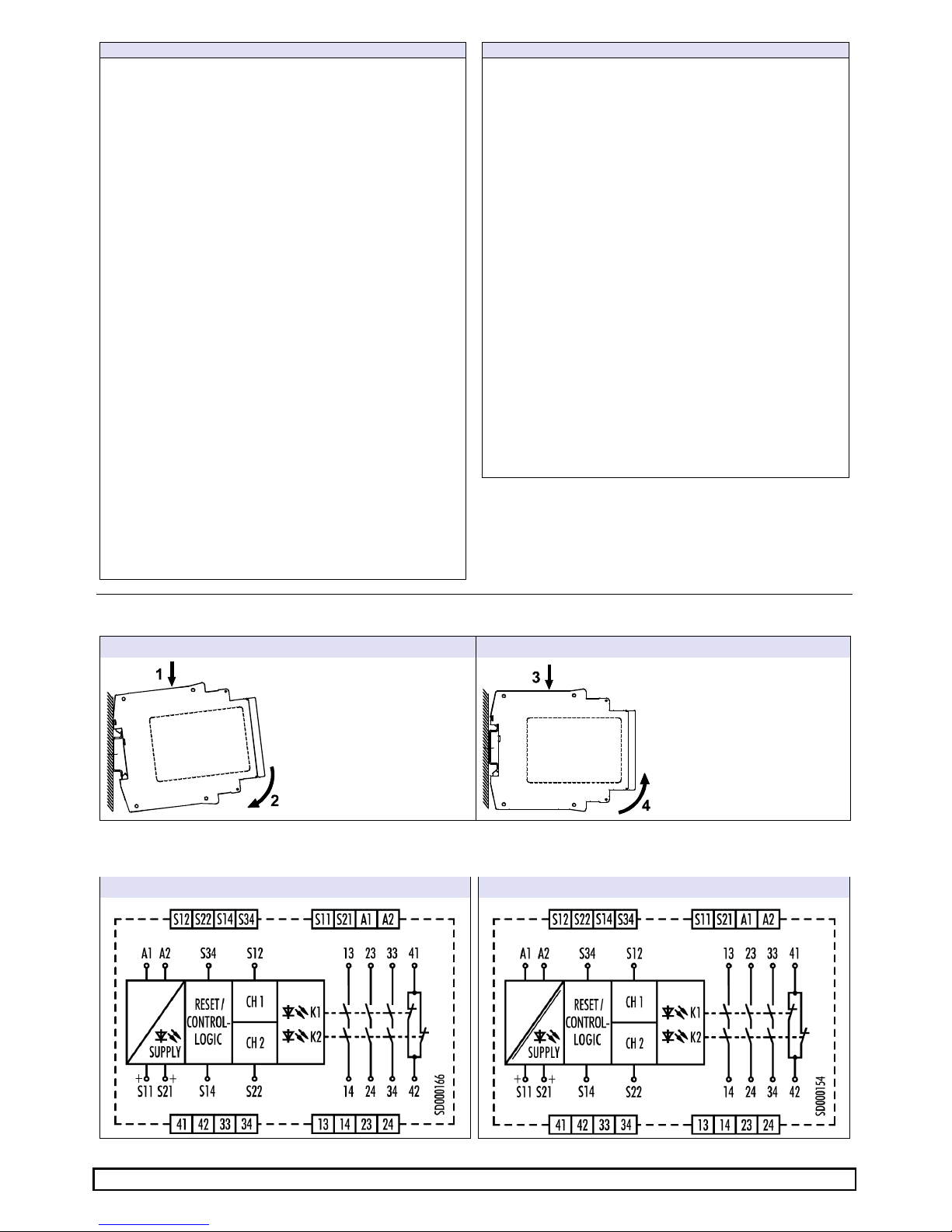
3Montage
4Klemmenschaltbilder
SNO
4083KM
… DC
24
V
SNO
4083KM
… AC
115
-
230
V
Montage
Demontage
1.
Gerät auf die Hutschiene
einhängen
2.
Durch leichten Druck in
Pfeilrichtung Gerät auf die
Hutschiene aufschnappen.
3. Gerät in Pfeilrichtung herun-
terdrücken.
4. Im heruntergedrückten Zu-
stand Gerät in Pfeilrich
tung
aus der Verrastung lösen
und von der Hut
schiene
nehmen.

Doc. # BA000773 – 11/2014 (Rev. H) SNO 4083KM DE 3
5Funktionsdiagramme
Äquivalente Ansteuerung mit manuellem Start (Installation 1, 2, 3, 4, 5, 8)
A1
S11
S12 (CH1)
S22 (CH2)
LED K1
LED K2
S34 (Reset)
13/14
23/24
33/34
41/42
tB
tStBR
tM
tA
tR1
tStBR tM
tA
tR2
tW
Antivalente Ansteuerung mit automatischen Start (Installation 6, 7)
A1
S11
S12 (CH1)
S22 (CH2)
LED K1
LED K2
S34 (Reset)
13/14
23/24
33/34
41/42
tB
tA
tR1
tStA
tR2
tW
Hinweis:
LED blinkt
LED
leuchtet
perma
nent

Doc. # BA000773 – 11/2014 (Rev. H) SNO 4083KM DE 4
6Installation
1 – Not-Aus-Taster, einkanalig 2 – Not-Aus-Taster, zweikanalig ohne
Querschlusserkennung
S12 S22 S21 S11 S14
S22
S12 S21 S11 S14
3
–
Sicherheitslichtgitter BWS Typ 4, zweikanalig und
Querschlusserkennung durch die BWS1)
4
–
Not
-
Aus Taster, zweikanalig mit
Querschlusserkennung
BWS type 4
with OSSD
S12 S22 S21 S11 S14
S11 S12 S21 S22 S14
5 – Schaltmatte, zweikanalig mit Querschlusserkennung
6
–
Magnetschalter, zweikanalig antivalent mit
Querschlusserkennung
S11 S21 S22 S12 S14
Safety mat
S11 S21 S12 S22 S14
Type SMA
actuated
7
–
Reset, automatisch mit und ohne Rückführkreis
8
–
Reset, manuell überwacht mit und ohne Rückführkreis
S11 S34
K11 ... K13
S11 S34
S21 S34
K11 ... K13
S21 S34
1) Diese Installationen sind für Geräte mit UB= 115-230 V AC nicht geeignet
Doc. # BA000773 – 11/2014 (Rev. H) SNO 4083KM DE 5
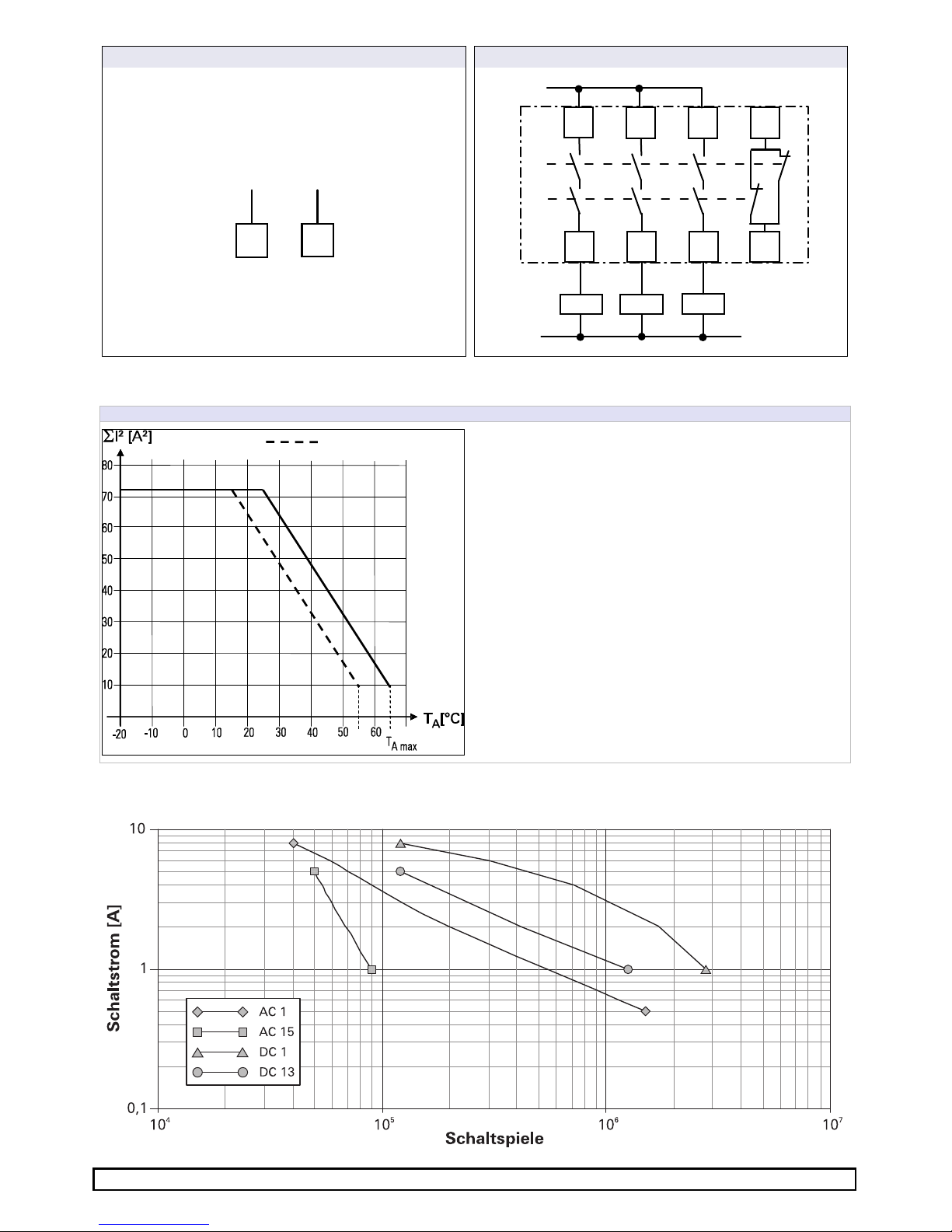
9
–
Versorgung
1
0
–
Ausgäng
e
A1 A2
L+ / L1 M / N
14
13
24
23
34
33
42
41
K1
K2
K11 K12 K13
L+/L1
M/N
7Kontaktlast-Derating
I²
–
Summenstrom
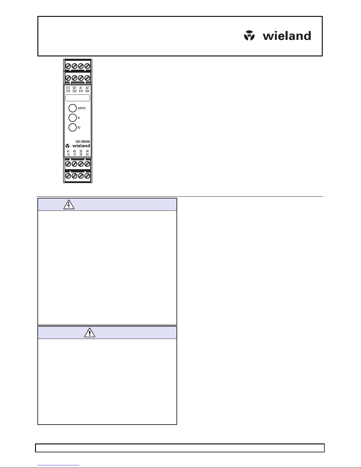
8Relais-Lebensdauer
UL508

Doc. # BA000773 – 11/2014 (Rev. H) SNO 4083KM DE 6
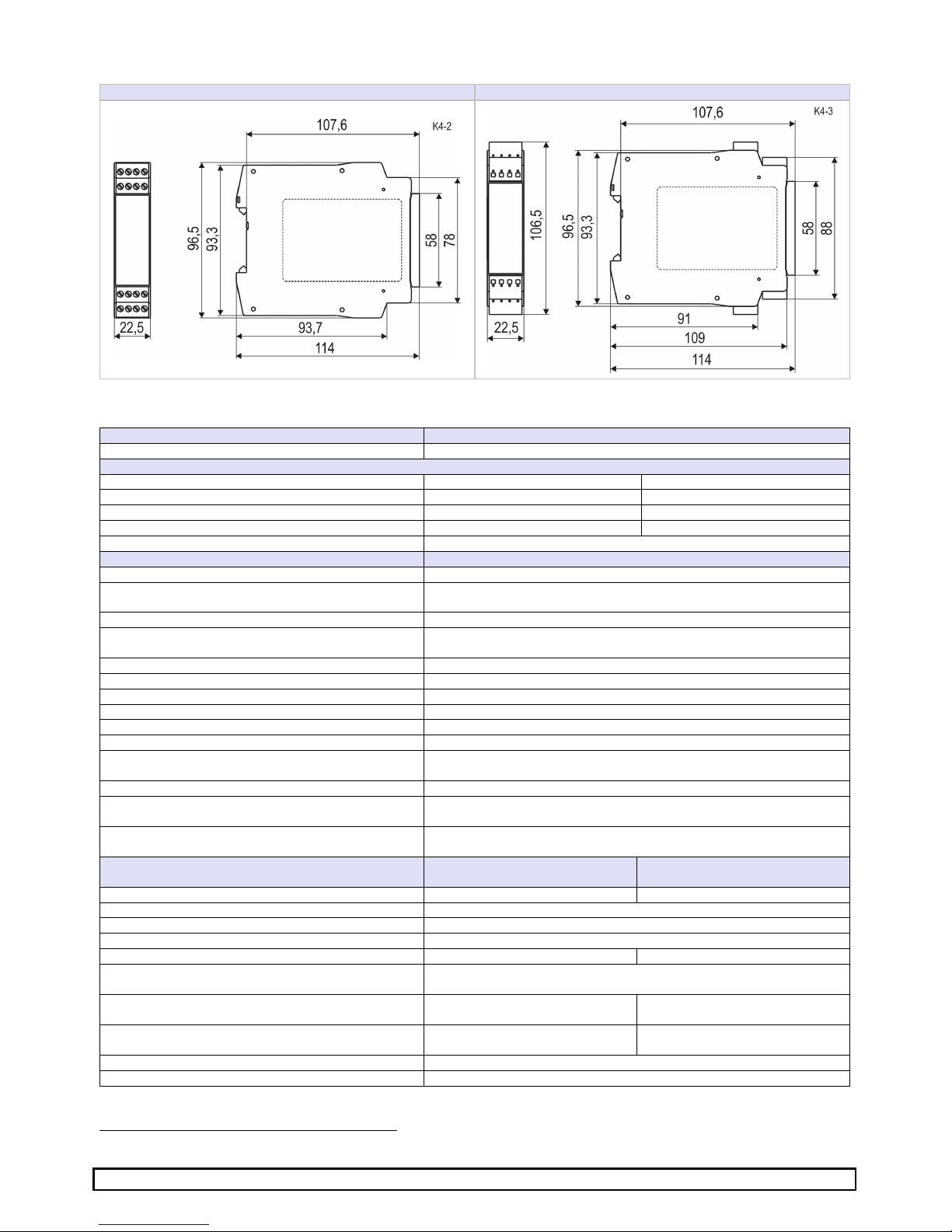
9Abmessungen
SNO 4083KM
-
A Schraubklemme
SNO 4083KM
-
C Federkraftklemme
10 Technische Daten
Funktion
Not-Aus-Relais
Funktionsanzeige 3 LED, grün
Versorgungskreis
A1/A2
Nennspannung U
N
24 V DC 115–230 V AC
Betriebsspannungsbereich U
B
: 0,85–1,2 × U
N
20,4 bis 28,8 V DC 97 bis 253 V AC
Bemessungsleistung 1,6 W 1,8 W / 4,0 VA
Nennfrequenz 50–60 Hz
Bereitschaftszeit t
B
max. 1,2 s
Steuerkreise
Eingangsspannung 19,2 … 28,8 V DC
Eingangsstrom (typ./max.) S12 / S22
S14 / S34
25 / 100 mA
3 / 5 mA
Ansprechzeit t
A
250 ms
Mindesteinschaltdauer t
M
(manueller Start, min./max.) 125 ms / 5 s
Bereitschaftszeit für Reset t
BR
> 4 ms
Wiederbereitschaftszeit t
W
120 ms
Rückfallzeit t
R
1
(typ. / max.) 12 / 35 ms
Rückfallzeit t
R2
bei Abfall A1 max. 200 ms
Synchronzeitüberwachung t
S
siehe Typenschild
Testpuls S11 (Länge / Intervall) 4 ms / 200 ms
Testpuls S12, S22: Länge / Intervall (Installation 3) < 0,8 ms / > 5,5 ms
Testpulsverhältnis S12, S22: Länge / Intervall (Instal-
lation 3)
< 7 %
Testpulslänge t
TR
, des eingehenden Testpulses < 16 ms
Verzögerungszeit tD(zeitlicher Versatz zwischen
Testpuls und eingehendem Testpuls)
< 48 ms
Max. Leitungswiderstand pro Kanal
2
)
24 V DC (5 + ((1,176 × U
B
/ 24 V) – 1) × 200)
Ω
115–230 V AC 12
Ω
Ausgangskreise
Freigabestrompfade
13/14, 23/24, 33/34
Meldestrompfade
41/42
Kontakt Schließer Öffner
Kontaktart zwangsgeführt
Kontaktwerkstoff AG-Legierung, vergoldet
Schaltnennspannung U 230 V AC
Max. thermischer Dauerstrom
I
TH
6 A 2 A
Max. Summentrom I
N
2
55 °C 25 A
2
(UL 508: 9 A
2
)
65 °C 9 A
2
Gebrauchskategorie AC-15 U
e
230 V, I
e
5 A
DC-13 U
e
24 V, I
e
5 A
Kurzschlussschutz Schmelzsicherung 6 A Klasse gG,
Schmelzintegral < 100 A²s
Bedingter Kurzschlußstrom 1000 A
Mechanische Lebensdauer 10 x 10
6
Schaltspiele
2) Werden 2-kanalige Geräte einkanalig eingesetzt, dann halbiert sich der Wert.

Doc. # BA000773 – 11/2014 (Rev. H) SNO 4083KM DE 7
Klemmen
-
und Anschlussdaten
Schraubklemmen
Federkraftklemmen
(TWIN)
Eindrähtig oder feindrähtig 1 x 0,2 mm² bis 2,5 mm²
2 x 0,2 mm² bis 1,0 mm²
1 x 0,2 mm² bis 1,5 mm²
Feindrähtig mit Aderendhülse nach DIN 46228 1 x 0,25 mm² bis 2,5 mm²
2 x 0,25 mm² bis 1,0 mm²
1 x 0,25 mm² bis 1,5 mm²
Leitergröße AWG (nur Cu-Leitungen verwenden) 26–14 24–16
Maximales Anzugsdrehmoment 0,5 bis 0,6 Nm (5-7 lbf-in)
Abisolierlänge 7 mm
Allgemeine Daten
Luft- und Kriechstrecken zwischen den Stromkreisen EN 60664-1
Ausgangskreise 1 13/14 und 23/24
Ausgangskreise 2 33/34 und 41/42
Versorgungskreis A1/A2
Steuerkreise S11, S12, S21, S22, S14 und S34
Sichere Trennung
– Bemessungsspannung 300 V
– Überspannungskategorie IV (6kV)
Ausgangskreise 1 - Ausgangskreise 2
Ausgangskreise 1 und 2 - Versorgungskreis
Ausgangskreise 1 und 2- Steuerkreise
Basisisolierung
– Bemessungsspannung 300 V
– Überspannungskategorie III (4kV)
Ausgangskreise 1
Ausgangskreise 2
Versorgungskreis - Steuerkreise (nur bei 115-230 V AC)
Schutzart nach EN 60529 Gehäuse / Klemmen IP40 / IP20
Betriebsumgebungstemperatur –25 bis +65 °C (UL508: -25 bis +55°C)
Lagertemperatur –25 bis +75 °C
Gewicht 0,2 kg
Normen EN ISO 13849-1, EN 62061, EN 81-1, EN 50156-1
Zulassungen TÜV, cULus
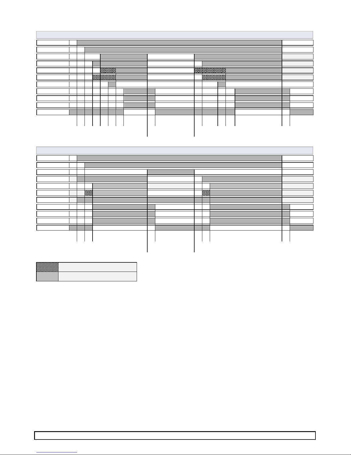
11 Fehlercodes und Fehlerbehebung
Blinkcode (SUPPLY
-
LED
)
2
Querschluss, behebbar durch Beseitigung des Querschlusses im laufenden Betrieb
3
Ablauffehler, Verletzung der korrekten Abfolge bei zweikanaliger Ansteuerung, behebbar im laufenden Betrieb
durch erneute korrekte Betätigungsabfolge
4
Synchronzeitfehler, Überschreitung der Synchronzeit bei zweikanaliger Ansteuerung, behebbar im laufenden
Betrieb durch Einhaltung der Synchronzeit
5
Überschreitung der maximalen Reset-Betätigungsdauer, behebbar im laufenden Betrieb durch erneute Reset-
Betätigung mit korrekter Dauer
6
Konfigurationsfehler, behebbar durch Anlegen der korrekten Klemmenbelegung für die gewünschte Konfigurati-
on, Gerät aus/einschalten erforderlich
7
Unter- / Überschreitung der zulässigen Eingangsspannungsgrenzen an S12 und S22, behebbar durch korrektes
Einstellen der Versorgungsspannung, Gerät aus/einschalten erforderlich
8
Temperatur im Gerät zu hoch, behebbar durch Verringerung der Kontaktlasten oder der Umgebungstemperatur,
Gerät aus/einschalten erforderlich
≥
12
Internes Überwachungsereignis, bitte tauschen Sie das Gerät aus und kontaktieren Sie den Kundendienst
Sollte ein Fehler auch nach der Beseitigung der Ursache weiterhin angezeigt werden, dann müssen die Eingänge S12, S22, S14
und S34 bei Power-on offen gehalten werden (z.B durch Abziehen des Steckers). Der Fehler sollte dann gelöscht sein und es
kann mit der gewünschten Installation durch Power-off und Power-on neu gestartet werden.
Instructions
(Translation of the original instructions)
SNO 4083KM
Wieland Electric GmbH
Brennerstraße 10-14
D-96052 Bamberg
Tel. +49 (0) 951 / 9324 -0
Fax +49 (0) 951 / 9324 -198
www.wieland-electric.com
Doc. # BA000773 – 11/2014 (Rev. H) SNO 4083KM EN 8
Basic device for EMERGENCY STOP and safety door applications
•Basic device according to EN 60204-1:2007 and EN ISO 13849-1:2007 for single or
two-channel EMERGENCY STOP monitoring.
•PL e / category 4 according to EN ISO 13849-1:2007
•SILCL 3 according to DIN EN 62061:2005
•Stop category 0 according to DIN EN 60204-1
•Manual or automatic start
•With / without crossover detection
•Feedback circuit for monitoring external contactors
•Three enabling current paths, one messaging current path
•Evaluation unit for BWS 4 according to EN 61496-1
•Usage according to EN 81-1 and EN 50156-1
•For connection in series with a pressure sensitive mat according to EN 1760-1
Device versions
SNO 4083KM-A DC 24 with screw terminals, pluggable
SNO 4083KM-A AC 115-230 V with screw terminals, pluggable
SNO 4083KM-C DC 24 V with spring-loaded terminals, pluggable
SNO 4083KM-C AC 115-230 V with spring-loaded terminals, pluggable
Front view
Supply LED green, power supply indicator
K1, K2 LED green operating and status display for relays K1, K2 and the
safety circuits.
SAFETY REGULATIONS
•
Installation, commissioning, modification and retrofitting
must only be performed by a qualified electrician.
•Disconnect the device / the system from the power supply
before starting work. In the case of installation and system
errors, mains voltage can be present on the control circuit in
the case of non-galvanically isolated devices.
•Observe the electrotechnical and professional trade associa-
tion safety regulations for installation of the equipment.
•Opening the case or other manipulation voids any war-
ranty.
•In the case of improper use or any use other than for the
intended purpose, the device must no longer be used and
any warranty claim is void. Invalidating causes can be:
strong mechanical loading of the device, such as occur
when falling or voltages, currents, temperatures, humidity
outside the specifications.
•Always check all safety functions in accordance with the
applicable regulations during initial commissioning of your
machine / system and observe the specified inspection
cycles for safety devices.
WARNING
•
Take the following safety precautions before starting
installation / assembly or dismantling:
1. Disconnec
t the device / the system from the power
supply before starting work.
2. Secure the machine / system against being switched on
again.
3. Confirm that no voltage is present.
4. Ground the phases and short to ground briefly.
5. Cover and shield neighbouring live parts.
6. The devices must be installed in a switch cabinet with a
protection class of at least IP54.
•Limited contact protection! Protection class according to
EN 60529:
−Case / terminals: IP40 / IP20.
−Finger-proof according to EN 50274.
1Proper use
The devices are safety switching devices. They must only be
used as components of safety equipment on machines that is
intended for the protection of persons, material, functions and
machinery.
2Function
The device is a two-channel safety switching device for EMER-
GENCY STOP equipment according to EN 60204-1. It performs
self-monitoring during each ON-OFF cycle and is equipped with
positively driven relays. The device is suitable for connection in
series with short-circuiting pressure sensitive mats, pressure
sensitive bumpers or switching edges with 4-wire technology
(without a monitoring resistor).
Basic function: After applying the supply voltage to the
terminals A1/A2 and closed safety inputs, the enabling current
paths are closed when a valid reset signal is established at S34.
The enabling current paths are opened when the safety inputs
are opened / de-energized.
Operating modes / System functions
•Single-channel or two-channel actuation
•With or without crossover detection
•Manual start (triggering with falling edge)
•Automatic start
•Evaluation of signal transmitters featuring equivalent or non-
equivalent switching

Doc. # BA000773 – 11/2014 (Rev. H) SNO 4083KM EN 9
NOTE
•
The performance level (PL) and safety category in accord-
ance with EN ISO 13849-1 depend on the external wiring,
the application case, the choice of control device and how
this is physically arranged on the machine.
•The user must carry out a risk assessment in accordance
with ISO 14121-1.
•The entire system / machine must undergo validation in
accordance with the applicable standards on the basis of this.
•The stated performance level will only be achieved if, taking
into account the prevailing device load (see EN ISO 13849-1
Table C.1) and the application case, an average number of
switching cycles per year is not exceeded (see EN ISO
13849-1, C.2.3 and Table K.1). Assuming that the B10d
value is 400,000 for the maximum load, the maximum cycle
number would be 400,000 / 0.1 x 30 = 133,333 switching
cycles per year.
•
The safety-related characteristics only apply when the relays
are switched at least once per year.
•
Operating the device other than specified can result in
malfunctions or destruction of the device.
•
The device must be checked to ensure it is in perfect
working order before commissioning, after replacement of
modules and/or in the case of changes to an installation that
has already undergone acceptance.
•
For operation at 115–230 V AC, the operating equipment of
the control circuits must be designed for a rated voltage of
300 V. Basic isolation between supply and control circuits.
•
The specified times must always be adhered to when
operating the device; otherwise, the device may become
locked. Locking may be reversed by opening the safety
inputs in the proper manner.
•
The expansion units of the SNE series or external contactors
with positively-driven contacts can be used for duplicating
the enabling current paths
NOTE
•
The contacts must be fused with maximum 6 A operating
class gG.
•
Control outputs S11 and S21 are equipped with overload
protection (for short circuits). Once the cause of the error
has been rectified, the device is ready for operation again
after approx. 3 s.
•
The control inputs and outputs are only used for the con-
nection of control devices and not for the connection of
external consumers such as lamps, relays or contactors.
•
External loads must be equipped with a suitable protection
circuit for the load (e.g. RC elements, varistors, suppressors,
etc.) in order to reduce electromagnetic interference and
increase the service life of the output switching elements.
•
The application-specific standards must be observed when
installing and operating the device.
•
In the case of an external incoming supply for inputs S12
and S22 (e.g. via the OSSD of electrosensitive protective
equipment (installation 3) there is no assurance that the
relays can be deactivated by interrupting or isolating the
supply voltage at A1 / A2. The relays are deactivated when
the safety circuits are opened.
•The safety functions have not been checked by UL. The
certification process has been carried out in accordance
with the requirements for general applications as stipulated
by UL508.
3Mounting
4Terminal diagram
SNO 4083KM… DC 24 V
SNO
4083KM
… AC
115
-
230
V
Mounting
Dismantling
1.
Attach the device to the DIN
rail.
2.
Snap the device on to the
DIN rail by applying slight
pressure in the direction of
the arrow.
3. Press the
device down in
the direction of the arrow.
4.
While pressed down,
detach the device from the
latching (in the direction
indicated by the arrow) and
remove it from the DIN rail.
Doc. # BA000773 – 11/2014 (Rev. H) SNO 4083KM EN 10
5Function diagrams
Equivalent actuation with manual start (installation 1, 2, 3, 4, 5, 8)
A1
S11
S12 (CH1)
S22 (CH2)
LED K1
LED K2
S34 (Reset)
13/14
23/24
33/34
41/42
tB
tStBR
tM
tA
tR1
tStBR tM
tA
tR2
tW
Non-equivalent actuation with automatic start (installation 6, 7)
A1
S11
S12 (CH1)
S22 (CH2)
LED K1
LED K2
S34 (Reset)
13/14
23/24
33/34
41/42
tB
tA
tR1
tStA
tR2
tW
Notice:
LED blinking
LED permanently lit

Doc. # BA000773 – 11/2014 (Rev. H) SNO 4083KM EN 11
6Installation
1 – EMERGENCY STOP button, single-channel 2 – EMERGENCY STOP button, two-channel without
crossover detection
S12 S22 S21 S11 S14
S22
S12 S21 S11 S14
3
–
Safety light curtain BWS type 4, two
-
channel with
crossover detection by BWS1)
4
–
EMERGENCY STOP button, two
-
channel with
crossover detection
BWS type 4
with OSSD
S12 S22 S21 S11 S14
S11 S12 S21 S22 S14
5
–
Pressure sensitive mat, two
-
channe
l with crossover
detection
6
–
Solenoid switch, two
-
channel, non
-
equivalent, with
crossover detection
S11 S21 S22 S12 S14
Safety mat
S11 S21 S12 S22 S14
Type SMA
actuated
7 – Reset, automatic, with and without feedback circuit
8
–
Reset, manual, monitored, with and without
feedback
circuit
S11 S34
K11 ... K13
S11 S34
S21 S34
K11 ... K13
S21 S34
1 ) These installation types are not suitable for devices where UB= 115-230 V AC.

Doc. # BA000773 – 11/2014 (Rev. H) SNO 4083KM EN 12
9
–
Power supply
1
0
–
Outputs
A1 A2
L+ / L1 M / N
14
13
24
23
34
33
42
41
K1
K2
K11 K12 K13
L+/L1
M/N
7Contact load derating
I²
–
Total current
8Relay service life
UL508
Switching cycles
Switching current [A]
Doc. # BA000773 – 11/2014 (Rev. H) SNO 4083KM EN 13
9Dimensions
SNO 4083KM
-
A screw terminal
SNO 4083KM
-
C spring
-
loaded terminal
10 Technical data
Function
EMERGENCY STOP relay
Function indicator 3 LEDs, green
Power circuit
Rated voltage U
N
24 V DC 115–230 V AC
Operating voltage range U
B
: 0.85–1.2 × U
N
20.4 to 28.8 V DC 97 to 253 V AC
Rated power 1.6 W 1.8 W / 4.0 VA
Nominal frequency 50-60 Hz
Standby time 1.2 s max.
Control circuits
Input voltage 19.2 to 28.8 V DC
Input current (typ. / max.) S12/S22
S14/S34
25 / 100 mA
3 / 5 mA
Response time (manual start t
A1
, autom. start t
A2
) 250 ms
Minimum activation time tM(manual start, min. /
max.)
125 ms / 5 s
Standby time for reset t
BR
> 4 ms
Recovery time t
W
120 ms
Release time t
R
(typ. / max.) 12 / 35 ms
Synchronous time monitoring t
S
1.5 s / 0.5 s (SNO 4083KM-A 0,5S)
Test pulse S11: length / interval 4 ms / 200 ms
Test pulse S12, S22: length / interval (Installation 3) < 0.8 ms / > 5.5 ms
Test pulse ratio S12, S22: length / interval (Installation
3)
< 7 %
Test pulse length t
TR
, of the incoming test pulse < 16 ms
Delay time tD(time between test pulse and incoming
test pulse)
< 48 ms
Max. line resistance per channel
2
)
24 V DC (5 + ((1.176 × U
B
/ 24 V) – 1) × 200)
Ω
115–230 V AC 12
Ω
Output circuits
Enabling current paths
13/14, 23/24, 33/34
Messaging current paths
41/42
Contact Normally open Normally closed
Contact type Positively driven
Contact material Ag alloy, gold plated
Rated switching voltage U 230 V AC
Max. thermal permanent current
I
TH
6 A 2 A
Max. total current I
N
2
55°C 25 A
2
(UL 508: 9 A
2
)
65°C 9 A
2
Utilisation category AC-15 U
e
230 V, I
e
5 A
DC-13 U
e
24 V, I
e
5 A
Short circuit protection 6 A class gG fuse,
fuse integral < 100 A²s
Conditional short-circuit current 1000 A
Mechanical service life 10
7
switching cycles
2 ) If only one of the channels on a 2-channel device is used, the value is halved.

Doc. # BA000773 – 11/2014 (Rev. H) SNO 4083KM EN 14
Terminals and connection data
Screw terminals
Spring
-
loaded ter
minals
(TWIN)
Single-core or finely stranded 1 x 0,2 mm² bis 2,5 mm²
2 x 0,2 mm² bis 1,0 mm²
1 x 0,2 mm² bis 1,5 mm²
Finely stranded with wire-end ferrule according to
DIN 46228
1 x 0,25 mm² bis 2,5 mm²
2 x 0,25 mm² bis 1,0 mm²
1 x 0,25 mm² bis 1,5 mm²
AWG conductor size (only use Cu wires) 26–14 24–16
Maximum tightening torque 0,5 bis 0,6 Nm (5-7 lbf-in)
Stripping length 7 mm
General data
Air gap and creepage paths between the circuits EN 60664-1
Output circuits 1 13/14 and 23/24
Output circuits 2 33/34 and 41/42
Power circuit A1/A2
Control circuits S11, S12, S21, S22, S14 and S34
Safety separation
– Rated voltage 300 V
– Overvoltage category IV (6kV)
Output circuits 1 — Output circuits 2
Output circuits 1 and 2— Power circuit
Output circuits 1 and 2— Control circuits
Basic insulation
– Rated voltage 300 V
– Overvoltage category III (4kV)
Output circuits 1
Output circuits 2
Power circuit — Control circuits (only 115-230 V AC)
Protection class according to EN 60529
case/terminals
IP40 / IP20
Ambient operating temperature –25 to +65 °C (UL508: -25 to +55°C)
Storage temperature –25 to +75 °C
Weight 0.2 kg
Standards EN ISO 13849-1, EN 62061, EN 81-1, EN 50156-1
Certifications TÜV, cULus
11 Error codes and correction
Flashing code
(SUPPLY
-
L
ED)
2
Crossover, can be rectified during operation
3
Process error, failure to observe the correct sequence for two-channel actuation, can be rectified during opera-
tion by repeating the actuation sequence correctly
4
Synchronous time error, synchronous time exceeded in the case of two-channel actuation, can be rectified
during operation by adhering to the synchronous time
5
Maximum reset actuating time exceeded, can be rectified during operation by repeating the reset with the
correct time
6
Configuration error, can be rectified by ensuring the correct terminal assignment for the required configuration,
the device has to be switched off and on again
7
Permissible input voltage limits undershot / overshot at S12 and S22, can be rectified by setting the correct
supply voltage, the device has to be switched off and on again
8
Device temperature too high, can be rectified by reducing the contact loads or the ambient temperature, the
device has to be switched off and on again
≥
12
Internal monitoring event, please replace the device and contact after sales service
If an error is still indicated even after the cause has been rectified, inputs S12, S22, S14 and S34 must be kept open during
power-on (e.g. pull out the connector). The error should then be cleared and you can perform a restart with the required installa-
tion by means of a power-off and power-on operation.
Notice d’instructions
(traduction de la notice originale)
SNO 4083KM
Wieland Electric GmbH
Brennerstraße 10-14
D-96052 Bamberg
Tel. +49 (0) 951 / 9324 -0
Fax +49 (0) 951 / 9324 -198
www.wieland-electric.com
Doc. # BA000773 – 11/2014 (Rev. H) SNO 4083KM FR 15
Module de base pour applications de porte d'arrêt d'urgence et de porte de protec-
tion
•Appareil de base selon les normes EN 60204-1:2007 et EN ISO 13849-1:2007 pour une surveil-
lance d'arrêt d'urgence monocanal ou bi-canal
•PL e / Catégorie 4 selon la norme EN ISO 13849-1:2007
•SILCL 3 selon la norme DIN EN 62061:2005
•Catégorie d'arrêt 0 selon la norme EN 60204-1
•Démarrage manuel ou automatique
•Avec / sans détection de court-circuit transversal
•Boucle de retour pour la surveillance des contacteurs-disjoncteurs externes
•3 trajets du courant de validation, 1 trajet du courant de signalisation
•Unité d'évaluation pour BWS 4 selon EN 61496-1
•Utilisation selon EN 81-1 et EN 50156-1
•Pour une connexion à la suite d'un tapis sensible selon EN 1760-1
Versions des appareils
SNO 4083KM-A DC 24 V avec bornes à vis, enfichables
SNO 4083KM-A AC 115-230 V avec bornes à vis, enfichables
SNO 4083KM-C DC 24 V avec bornes à ressort, enfichables
SNO 4083KM-C AC 115-230 V avec bornes à ressort, enfichables
Vue de face
Supply LED verte pour l'affichage de la tension de service
K1, K2 LED verte pour l'affichage de fonctionnement et d'état des relais K1, K2 et des
circuits de sécurité.
CONSIGNES DE SÉCURITÉ
•
Seul un électricien qualifié est habilité à effectuer le montage, la
mise en service, la modification et le rééqui-pement !
•Avant de commencer les travaux, mettre l'appareil/l'installation
hors tension! En cas de défauts de montage et de l'installation,
avec les modules non séparés galvaniquement, le circuit de
commande peut être sous potentiel réseau !
•Pour l'installation des modules, veuillez observer les consignes de
sécurité en matière d'électronique et celles de la caisse profes-
sionnelle d'assurance-accidents.
•L'ouverture de l'appareil ou toute autre manipulation entraîne
l'extinction de la garantie.
•En cas d'utilisation incorrecte ou d'utilisation non confor-me à
l'usage prévu, le module ne doit plus être utilisé et tout droit à la
garantie est annulé. Exemples d'effets inad-missibles : Forte
sollicitation mécanique du module, com-me p. ex. en cas de
chute, de tensions, de courants, de températures, d'humidité
hors spécification.
•Lors de la première mise en service de votre machine / installa-
tion, veillez à vérifier systématiquement que toutes les fonctions
de sécurité sont conformes aux pres-criptions applicables et
observez les cycles de contrôle préconisés pour les dispositifs de
sécurité.
AVERTISSEMENT
•
Avant de procéder à l'installation, au montage ou au démontage,
veuillez appliquer les mesures de sécurité suivantes :
1. Avant de commencer les travaux, mettre le
module/l'installation hors tension !
2. Protéger la machine /l'installation contre toute remise en
marche intempestive !
3. S'assurer de l'absence de tension !
4. Mettre les phases à la terre et les court-circuiter !
5. Recouvrir et isoler les parties sous tension voisines !
6. Le montage des modules doit s'effectuer dans une armoire de
commande possédant un indice de protection minimal
d'IP
54.
•
Protection limitée contre les contacts accidentels !
Indice de protection conforme à la norme EN 60529.
−Boîtier / bornes : IP 40 / IP 20.
−Protection des doigts selon la norme EN 50274.
1Utilisation conforme à l'usage
prévu
Les modules sont des modules de coupure de sécurité. Ils ne
doivent être mis en œuvre qu'en tant qu'élément de dispositifs
de protection sur des machines et sont dédiés à la protection
des personnes, du matériel, des fonctions et des machines.
2Fonction
Le module est un module de coupure de sécurité bi-canal,
autocontrôlé pour chaque cycle de MARCHE-ARRÊT pour
dispositifs d'arrêt d'urgence selon la norme EN 60204-1, doté
de relais à commande forcée. Le modèle est conçu pour une
connexion à la suite de tapis sensibles, de barres ou de bords
sensibles à court-circuit en technique à 4 conducteurs (sans
résistance de surveillance).
Fonctionnement de base : Après application de la tension
d'alimentation aux bornes A1 / A2 et une fois les entrées de
sécurité fermées, les trajets du courant de validation sont
fermés dans le cas d'un signal de réinitialisation à S34. L'ouver-
ture/la désexcitation des entrées de sécurité permet d'ouvrir les
trajets du courant de validation.
Modes de fonctionnement / Fonctions système
•Pilotage monocanal ou bi-canal
•Avec ou sans détection de court-circuit transversal
•Démarrage manuel (déclenchement avec front descendant)
•Démarrage automatique
•Évaluation de transmetteur de signaux à commutation en
phase ou en opposition de phase

Doc. # BA000773 – 11/2014 (Rev. H) SNO 4083KM FR 16
REMARQUES
•
Le niveau de performance (« Performance Level », PL) et la
catégorie de sécurité selon la norme EN ISO 13849-1 dé-
pendent du câblage extérieur, du cas d’application, du choix
du transmetteur d’ordres et de l’agencement sur la machine
sur place.
•L’utilisateur doit effectuer une évaluation du risque confor-
mément à la norme ISO 14121-1.
•Il convient de réaliser sur cette base une validation de
l’ensemble de l’installation / de la machine selon les normes
applicables.
•Le niveau de performance indiqué ne pourra être atteint,
selon la charge présente du module (cf. EN ISO 13849-1,
tab. C.1) et le cas d’application, que si un nombre moyen de
cycles de commutation par an n’est pas dépassé (cf. EN ISO
13849-1, C.20,3 et tab. K.1). Avec une valeur B10d donnée
de 400 000 cycles de commutation pour une charge maxi-
male, on obtient par ex. un nombre maximal de cycles de
400 000 / (0,1 × 30) = 133 333 cycles de commutation par
an.
•
Les grandeurs caractéristiques de sécurité ne sont valables
que si les relais sont commutés au minimum une fois par
an.
•
L'exploitation du module en dehors de la spécification peut
entraîner des dysfonctionnements ou une destruction du
module.
•
Avant la mise en service, après le remplacement de mo-
dules et/ou en cas de modifications sur une installation déjà
réceptionnée, il faut procéder à une vérification du fonc-
tionnement correct.
•
Lors d'un fonctionnement avec 115–230 V CA, les moyens
d'exploitation des circuits de commande et de signalisation
doivent être conçus de manière à supporter une tension
assignée de 300 V. Isolation de base entre d'une part le
circuit d'alimentation et d'autre part, le circuit de com-
mande.
•
En principe, il convient de respecter les temps indiqués lors
du fonctionnement de l'appareil, sous peine de le verrouil-
ler. L'ouverture conforme des entrées de sécurité permet
d'annuler le verrouillage de l'appareil.
REMARQUES
•
Pour la reproduction des trajets du courant de validation, il
est possible d'utiliser les modules d'extension de la gamme
SNE ou des contacteurs-disjoncteurs externes dotés de
contacts à commande forcée.
•
Les contacts doivent être protégés avec 6 A max. classe de
service gG.
•
Les sorties de commande S11 et S21 sont équipés d'un
système de protection contre les surcharges (en cas de
court-circuit). Une fois la cause du défaut éliminée, le mo-
dule est à nouveau opérationnel après 3 s environ.
•
Les entrées et les sorties de commande servent exclusive-
ment au raccordement de transmetteurs d'ordres et non au
raccordement de consommateurs externes, comme par ex.
des lampes, des relais ou des contacteurs-disjoncteurs.
•
Les charges externes doivent être équipées d'un circuit de
protection adapté à la charge (par ex. circuits RC, varis-
tances, suppresseurs, etc.) afin de réduire les perturbations
électriques et d'augmenter la durée de vie des modules de
coupure de sortie.
•
L'installation et l'exploitation de l'appareil requise la prise en
compte des normes spécifiques à l'application.
•
En cas d'injection externe au niveau des entrées S12 et S22,
par ex. via OSSD d'un dispositif de protection sans contact
(installation 3) une coupure des relais par interruption ou
coupure de la tension d'alimentation au niveau des bornes
A1/A2 ne peut pas être garantie. Les relais se coupent avec
l'ouverture des circuits de sécurité.
•Les fonctions de sécurité n'ont pas été contrôlées par la
norme UL. L'homologation est réalisée selon les exigences
relatives aux applications générales de la norme UL508.
3Montage
4Schéma de connexion des bornes
SNO 4083KM… DC 24 V
SNO
4083KM
… AC
115
-
230
V
Montage
Démontage
1.
Accrocher l'appareil sur le
profilé chapeau
2.
Enclencher l'appareil sur le
profilé chapeau en exerçant
une légère pression dans le
sens de la flèche.
3.
Abaisser l'appareil dans le
sens de la flèche.
4.
Désolidariser l'appareil
abaissé de son enclenche-
ment dans le sens de la
flèche et le retirer du profilé
chapeau.

Doc. # BA000773 – 11/2014 (Rev. H) SNO 4083KM FR 17
5Diagramme fonctionnel
Pilotage en phase avec démarrage manuel (installation 1, 2, 3, 4, 5, 8)
A1
S11
S12 (CH1)
S22 (CH2)
LED K1
LED K2
S34(Réinitialis
a
tion)
13/14
23/24
33/34
41/42
tB
tStBR
tM
tA
tR1
tStBR tM
tA
tR2
tW
Pilotage en opposition de phase avec démarrage automatique (installation 6, 7)
A1
S11
S12 (CH1)
S22 (CH2)
LED K1
LED K2
S34(Réinitialis
a
tion)
13/14
23/24
33/34
41/42
tB
tA
tR1
tStA
tR2
tW
Remarque :
LED clignotante
LED allumée en permanence

Doc. # BA000773 – 11/2014 (Rev. H) SNO 4083KM FR 18
6Installation
1 – Poussoir d'arrêt d'urgence, monocanal 2 – Poussoir d'arrêt d'urgence, bi-canal sans détection de
court-circuit transversal
S12 S22 S21 S11 S14
S22
S12 S21 S11 S14
3
–
Grille lumineuse de sécurité BWS type
4, bi
-
canal et
détection de court-circuit transversal via BWS1)
4
–
Poussoir d'arrêt d'urgence, bi
-
canal avec détection de
court-circuit transversal
BWS type 4
with OSSD
S12 S22 S21 S11 S14
S11 S12 S21 S22 S14
5
–
Tapis sensible, bi
-
canal avec détection de court
-
circuit transversal
6
–
Commutateur magnétique, bi
-
canal en opposition de
phase avec détection de court-circuit transversal
S11 S21 S22 S12 S14
Safety mat
S11 S21 S12 S22 S14
Type SMA
actuated
7
–
Réinitialisation, automatique avec et sans boucle de
retour
8
–
Réinitialisation, manuelle surveillée avec et sans boucle
de retour
S11 S34
K11 ... K13
S11 S34
S21 S34
K11 ... K13
S21 S34
1 ) Ces installations ne sont pas adaptées aux appareils avec une tension UB= 115-230 V CA

Doc. # BA000773 – 11/2014 (Rev. H) SNO 4083KM FR 19
9
–
Alimentation
1
0
–
S
orties
A1 A2
L+ / L1 M / N
14
13
24
23
34
33
42
41
K1
K2
K11 K12 K13
L+/L1
M/N
7Réduction de la charge de contact
I²
–
Courant cumulé
8Durée de vie des relais
UL508
Manœuvres
Courant de coupure [A]

Doc. # BA000773 – 11/2014 (Rev. H) SNO 4083KM FR 20
9Dimensions
Borne à vis SNO 4083KM
-
A
Borne à ressort SNO 4083KM
-
C
10 Caractéristiques techniques
Fonction
Relais d'arrêt d'urgence
Affichage des fonctions 3 LED, vertes
Circuit d'alimentation
Tension nominale U
N
24 V CC 115–230 V CA
Plage de tension de service U
B
: 0,85–1,2 × U
N
20,4 à 28,8 V CC 97 à 253 V CA
Puissance assignée 1,6 W 1,8 W / 4,0 VA
Fréquence nominale 50-60 Hz
Temps de disponibilité pour la fonction de réinitialisa-
tion
max. 1,2 s
Circuits de commande
Tension d’entrée 19,2 … 28,8 V DC
Courant d'entrée (type / max.) S12/S22
S14/S34
25 / 100 mA
3 / 5 mA
Temps de réponse
(démarrage manuel t
A1
, démarrage autom. t
A2
)
250 ms
Durée minimale d'activation tM
(démarrage manuel, min. / max.)
125 ms / 5
Temps de disponibilité pour la fonction de réinitialisa-
tion t
BR
> 4 ms
Temps de réexcitation t
W
120 ms
Temps de retombée t
R
(type / max.) 12 / 35 ms
Surveillance de synchronisation t
S
1,5 s / 0,5 s (SNO 4083KM-A 0,5S)
D'impulsion test S11: longueur / intervalle 4 ms / 200 ms
D'impulsion test S12,S22: longueur / intervalle
(installation 3)
< 0,8 ms / > 5,5 ms
Rapport d'impulsion test S12, S22: longeur /intervalle < 7 %
Durée d'impulsion d'essai tTR, de l'impulsion d'essai
entrante
< 16 ms
Durée de temporisation tD(décalage temporel entre
l'impulsion d'essai et l'impulsion d'essai entrante)
< 48 ms
Résistance de ligne max. par canal
2
)
24 V CC (5 + ((1,176 × U
B
/ 24V) – 1) × 200)
Ω
115–230 V CA 12
Ω
Circuits de sorti
e
Trajets du courant de validation
13/14, 23/24, 33/34
Trajets du courant de signalisation
41/42
Contact à fermeture à ouverture
Type de contact à commande forcée
Matériau du contact Alliage AG, doré
Tension nominale de commutation U 230 V AC
Courant thermique permanent max.
I
TH
6 A 2 A
Courant cumulé max. I
N
2
55 °C 25 A
2
(UL 508: 9 A
2
)
65 C 9 A
2
Catégorie d'utilisation AC-15 U
e
230 V, I
e
5 A
DC-13 U
e
24 V, I
e
5 A
Protection contre les courts-circuits Fusible 6 A classe gG, joule
intégral < 100 A²s
Courant de court-circuit conditionnel 1000 A
Durée de vie mécanique 10
7
manœuvres
2 ) Si des appareils à deux canaux sont utilisés de façon monocanale, la valeur est divisée par deux.
Other manuals for SNO 4083KM
1
Table of contents
Languages:


