WiFi and scales RS232 User manual

Web Page Installation Guide
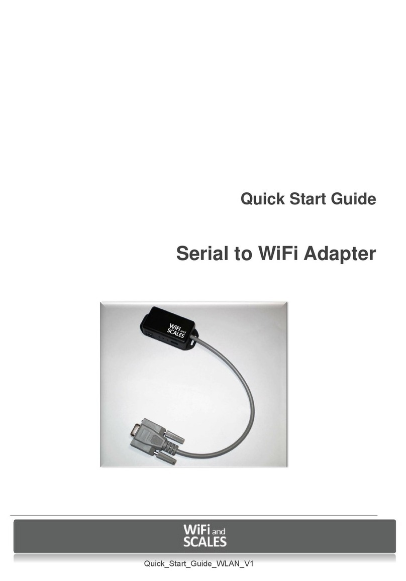
WiFi RS232 Adapter

WIFI ADAPTER Quick Start Guide, web page configuration www.wifiandscales.com
2
1 Introduction
This guide will help you install and configure the WIFI ADAPTER for the first time use. It describes how to
configure the required WiFi and IP parameters via the web interface so it can be connected to a serial port of a
scale.
2 Requirements
Things you need to have:
The WIFI and Scales Serial to WiFi 802.11b+g adapter
A WiFi Access Point that you have full control of (Does not have to be the actual AP the adapter is going to be
configured for)
A PC that connects to the Access Point via Ethernet or WiFi
A web browser installed on the PC
Things you need to know:
The SSID (the name) of the WiFi Network you want the Serial Adapter to connect to.
The Security Key of the WiFi Network
If you are to set a static IP address for the Serial WiFi adapter you need to know:
IP address to set
The network mask
The default gateway
3 The WIFI ADAPTER Connections
All input and outputs of the WIFI ADAPTER except for the DSUB-9 connector, is located on the side of the
adapter.
From left to right these are:
DC-jack for a 2.1 mm DC plug with positive sleeve and negative tip.
Factory reset button (accessed with a pin inserted to the hole)
Red LED indicates power.
Green LED indicates established connection (association) with a WLAN access point
Aux connector for additional equipment.

WIFI ADAPTER Quick Start Guide, web page configuration www.wifiandscales.com
3
4 Getting started with the WIFI ADAPTER
To simplify the setup it is convenient to use a PC with one Ethernet interface and one WLAN interface.
Connect the access point for configuration with an Ethernet cable and connect the Wireless LAN interface
to the production access point to which you wish to connect the WIFI ADAPTER adapter.
4.1 Configuring the WIFI ADAPTER via the web interface
4.1.1 Configuring the AP
Connect the PC to the access point. This is easiest done via Ethernet cable as we are going to
change the Wireless LAN parameters of the AP.
Log into the management of the AP and set the SSID to “HD-config”

WIFI ADAPTER Quick Start Guide, web page configuration www.wifiandscales.com
4
Figure 1: Setting SSID on a Linksys as an example
Turn off all wireless security
Figure 2: Turn off Wireless Security protocols (Linksys example)

WIFI ADAPTER Quick Start Guide, web page configuration www.wifiandscales.com
5
Set the network to 192.168.1.x with the AP as 192.168.1.1
Figure 3: setting local IP address (Linksys example)
DHCP server can be enabled as long as its starting address is higher than 192.168.1.23
Now we are done setting up the configuration Access Point.
Connect the serial to WiFi Adapter to a scale or power it up stand alone by connecting an 9V AC adapter.
Turn on the scale.
The Red LED that indicates power on the WIFI ADAPTER adapter should light up immediately. The green LED
that indication WLAN connection should come on a couple of seconds later. The RED led blinks to indicate
that the WIFI ADAPTER is in factory pre-set state.
Start a web browser on the PC and type the IP address 192.168.1.22 in the address field.
The default configuration web page of the serial adapter shall open in the browser.

WIFI ADAPTER Quick Start Guide, web page configuration www.wifiandscales.com
6
When the configuration page is displayed it displays the factory default settings in the form. See figure above.
This needs to be replaced with the applicable values for the network to be used.
Fill out the form with the all required data. Don’t forget to select “Security Type” with the radio buttons.
Click on Submit when all fields has been filled out
A confirmation page will be shown for 10 seconds before the WIFI ADAPTER adapter switches wireless
networks and connects to the network defined by the new settings

WIFI ADAPTER Quick Start Guide, web page configuration www.wifiandscales.com
7
As the WIFI ADAPTER adapter connects to the new network the webpage will disappear in some browsers.
The PC has to be connected the production network and the new IP address configured for the WIFI ADAPTER
adapter entered into the browser.
If the Serial to WiFi adapter needs to be reconfigured for another network the factory pre-set can be restored
by inserting the end of a paperclip into the small hole next to the DC-jack hold it for 5 seconds. The device will
restart itself and come up on the factory-pre set settings.
4.2 Restore factory settings
The WIFI ADAPTER can be returned to the configuration pre-set in manufacturing by following these
steps:
The reset button is located in the hole between the LEDs and DC jack.
Use a toothpick or another pin that fits the hole snugly.
Insert the pin straight into the hole and press the button for 5 sec.
The red and green led starts blinking simultaneously indicating that the unit is in factory settings mode.
If the WIFI ADAPTER is in serial port configuration mode it is NOT possible to restore factory
settings with the reset button, the command line is used instead as shown below:
$ db set /app/factory_preset 1
$ db store
$ reset
5 Using WIFI ADAPTER in Web server mode
The scale has to have the “Serial Port Mode” set to “0” = full duplex. How to do this is described in the
manual for the scale.
Turn the scale off before you plug in the adapter to the serial port. Fasten the adapter with the screws assure
a good connection. If the adapter is plugged in with the power on the scale may indicate battery low when
the adapter is connected.
For a scale that does not provide adapter power via the d-sub interface an external AC-DC adapter has to be
used. This should be a 9V AC-adapter with minus on the centre pin. The same type used by the scales.
Start a web browser at a PC connected to the same network as the WIFI ADAPTER and type in the address for
the WIFI ADAPTER in the address field.

WIFI ADAPTER Quick Start Guide, web page configuration www.wifiandscales.com
8
The webpage for the WIFI ADAPTER and the scale comes up shortly.
5.1 The WIFI ADAPTER scale web GUI
The following commands can be invoked via the web page. By clicking on the buttons
Web page key
Action
UPDATE
This command will update the scale reading. The indicator will show ERR if
the scale is in motion or inaccessible.
TARE
This command is sent to the indicator to tare the scale. The indicator will not
respond if the scale is in motion, positive overload or negative overload. The
indicator will also not respond if it is displaying a negative gross value.
ZERO
This command is sent to zero the scale. The indicator will not respond if the
scale is in motion, positive overload or negative overload. The indicator will
also not respond if it is not in gross mode or within the zero range specified in
F4 of the Setup Menu.
AUTO REFRESH ON/OFF
Toggles the automatic refresh of the web page on or off.
GR (if shown)
This command is sent to the indicator to revert to gross mode. The indicator
will not respond if the scale is in motion, positive overload or negative
overload. The indicator will also not respond if it is not in net mode.
NT (if shown)
This command is sent to the indicator to revert to net. The indicator will not
respond if the scale is in motion, positive overload or negative overload. The
indicator will also not respond if it is not in gross mode or a tare has yet to be
established.
Configure Alarm Settings
Opens the Alarm configuration page

WIFI ADAPTER Quick Start Guide, web page configuration www.wifiandscales.com
9

WIFI ADAPTER Quick Start Guide, web page configuration www.wifiandscales.com
10
5.2 Setting Alarm and Warning Levels
To get to the Alarm configuration page click the button “CONFIGURE ALARM SETTINGS” on the main scale
page.
It is possible to set alarm and warning levels for three parameters. Weight, External Temperature and
Internal Temperature. Note that external temperature measurement requires the SRN801 temperature
sensor connected to WIFI ADAPTER. To include external temperature on the web page the WIFI ADAPTER has
to be restarted by cycling the power.
For each of the measured parameters four alarm/warning trig levels can be set. The levels should be selected
so that “Low Alarm Level” < “Low Warning Level” < “High Warning Level” < “High Alarm Level”. Tick the box
above the levels to activate the alarm.
In the example below alarms for all measurements has been activated and all levels set.

WIFI ADAPTER Quick Start Guide, web page configuration www.wifiandscales.com
11
When a value is outside the warning range it is displayed in dark red and when it is outside the
alarm range it is displayed in bright red.See example below:
Known Issues
If WEP is used and the wrong key is entered the green LED will light up when the adapter is
associated with the AP even though no traffic is possible due the erroneous key.
In telnet mode does some terminal hide the minus sign for negative values.
The internal temperature sensor value jitters if external temp sensor is connected.
Table of contents
Other WiFi and scales Adapter manuals
Popular Adapter manuals by other brands
SMC Networks
SMC Networks EZ Connect g SMCWUSBT-G2 user guide
Extron electronics
Extron electronics VGA Line Driver P/2 DA1 user guide
Aztech
Aztech HL113 E user manual
NETGEAR
NETGEAR WNCE2001 - Ethernet to Wireless Adapter installation guide
Sagem
Sagem 3100MFPX - Phaser B/W Laser user guide
Gigabyte
Gigabyte GN-BTP01 user guide
