WIFLY-City ODU-9500-4E1 User manual

WIFLY-Cit
y
ODU
-
9500
-
4E1
Q
Qu
ui
ic
ck
k
I
In
ns
st
ta
al
ll
la
at
ti
io
on
n
G
Gu
ui
id
d
e
e
V
Ve
er
rs
si
io
on
n
1
1.
.0
0.
.
3
3
Jul. 2008
External Antenna

WARNINGS
Do not work on the system or connect or disconnect cables during periods of
lightning activity.
This equipment must be grounded. Never defeat the ground conductor or operate
the equipment in the absence of a suitably installed ground conductor. Contact the
appropriate electrical inspection authority or an electrician if you are uncertain that
suitable grounding is available.
Ultimate disposal of this product should be handled according to all national laws
and regulations.
Do not locate the antenna near overhead power lines or other electric light or power
circuits, or where it can come into contact with such circuits. When installing the
ODU, take extreme care not to come into contact with such circuits, as they may
cause serious injury or death. For proper installation and grounding of the antenna,
please refer to national and local codes (e.g. U.S.:NFPA 70, National Electrical Code,
Article 810, in Canada: Canadian Electrical Code, Section 54).
Only trained and qualified personnel should be allowed to install, replace, or service
this equipment.
The outdoor radio can be damaged by incorrect power application. Read and follow
the installation instructions carefully before connecting the system to its power
source.
PDH / Ethernet Convergent System Quick Installation Guide

Follow the guidelines in this installation guide to ensure correct operation and safe
use of the radio.
PDH / Ethernet Convergent System Quick Installation Guide

PACKAGECONTENTS
The package of 1 link PDH / Ethernet Convergent Radio you have received should contain the
following items:
•Indoor Unit (IDU) ………………………………………………………………………………………x2
•Outdoor Unit (ODU) ………………………………………....………...…………………...….x2
•Mounting Kit of ODU .…………………..……………………………..…….…………….……….….x2
•Bracket of IDU …………………………………………………………………………………………x2
•Product CD ….……………………………………………………………………...............…....……x2
•Quick Installation Guide ……………………………………………………………………..…..…….x2
•AC Power Code (AC version)…………………..………………………………….……….…….……x2
If any item on the above list is not included or damaged, please contact your local
vendor for support.
MECHANICALDESCRIPTION
Please refer to the following description for the meaning of each mechanical feature.
IDU:
Front Panel Introduction
PDH / Ethernet Convergent System Front Panel View
(1)
(2)
(3) (4)
(5)
(6)
PDH / Ethernet Convergent System Quick Installation Guide

(1) LAN Ethernet Connectors and Indicators
The Ethernet interface is a RJ45 connector with LED, connect this port to your desktop or
laptop first before you want to configure the ODU.
There are two green LED indicators:
zLink: green LED (Link Up/Down Status)
zAct: orange LED (TX/RXActive Status)
(2) E1 Interface
ACT: green LED (E1 Port Traffic)
ALM: orange LED (E1 Port Link Status)
The “Orange” LED indicates one of the following alarm occurred:
1. Local E1: LOS, AIS
2. Remote E1: L-bit
3. No received traffic from WAN port
(3) Reset Button
Provide the facility of rebooting the system.
(4) RS232 Connector
The RS232 interface with baud-rate 115200 bps via DB9 (female)-to-DB9 (male) cable is
provided for diagnostic. The user commands (CLI command) are listed in Table 3-4.1.
(5) NMT Port (10/100M Ethernet Port for Telnet, Web-based or SNMP-based Management)
Provide user-friendly interfaces—Telnet, Web or SNMP GUI, via NMT port for managing
the local IDU and remote IDUs.
(6) System Indicators
PWR (Power Exist LED)
ALM (for any of E1 Links or WAN port Status)
Off: Normal status
On: When the red LED lights, it indicates one of the following alarm occurred:
1. Local E1: LOS, AIS
2. Remote E1: L-bit
3. No received traffic from WAN port
PDH / Ethernet Convergent System Quick Installation Guide
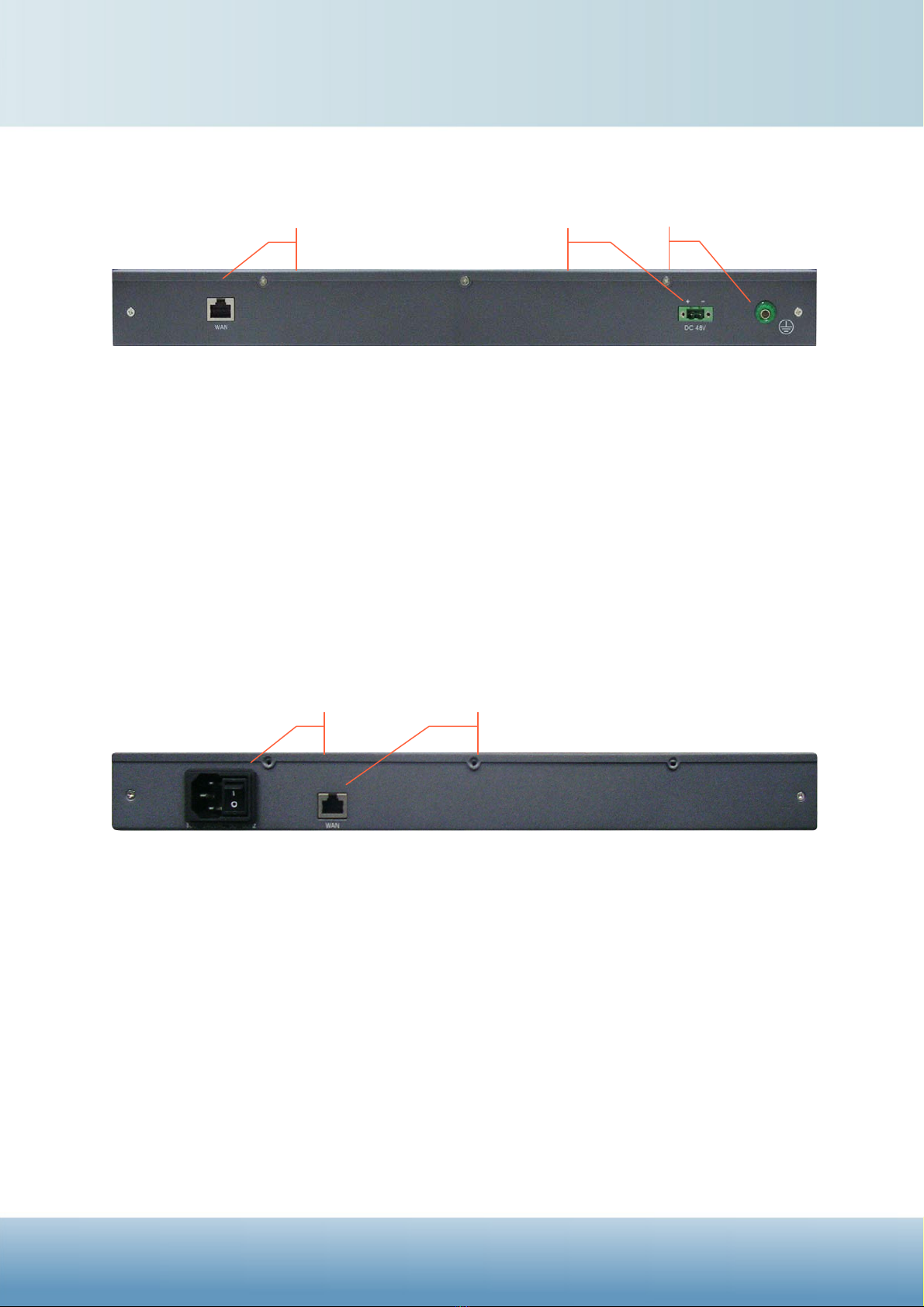
Rear Panel Introduction
DC version
PDH / Ethernet Convergent System Rear Panel View
(1)WAN Interface: (Connect to the ODU)
The Ethernet interface is a RJ45 connector which can connect to the ODU with the SFTP
cable, and provide the Ethernet signal and DC to the ODU.
(2)DC Power Socket:
±48V(-36V to -72V or 36V to 72V)
(3)Ground
Fasten a wire to the protection ground connector screw, and connect this wire to the
shielding ground.
AC version
PDH / Ethernet Convergent System Rear Panel View
(1) AC Power Socket and Switch (On/Off switch for AC):
The power module provides the power with 100 ~ 240VAC.
(2) WAN Interface: (Connect to the ODU)
The Ethernet interface is a RJ45 connector which can connect to the ODU with the SFTP
cable, and provide the Ethernet signal and DC to the ODU.
(1) (2)
(1) (2)
(3)
PDH / Ethernet Convergent System Quick Installation Guide
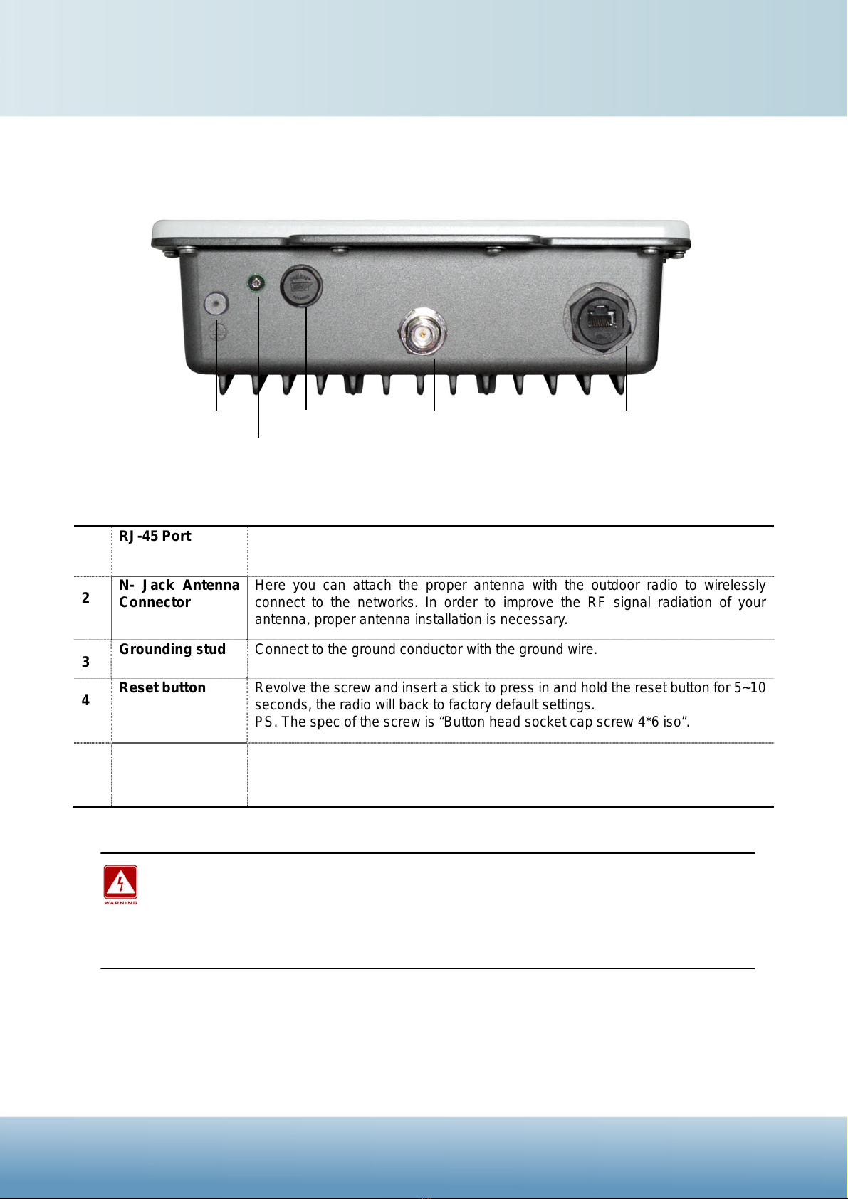
ODU:
Outdoor Multi-function Radio Figure
1 RJ-45 Port Use the SFTP cat.5 cable with weatherproof connector to connect to the “To
ODU” side of the POE injector.
2 N- Jack Antenna
Connector Here you can attach the proper antenna with the outdoor radio to wirelessly
connect to the networks. In order to improve the RF signal radiation of your
antenna, proper antenna installation is necessary.
3 Grounding stud Connect to the ground conductor with the ground wire.
4 Reset button Revolve the screw and insert a stick to press in and hold the reset button for 5~10
seconds, the radio will back to factory default settings.
PS. The spec of the screw is “Button head socket cap screw 4*6 iso”.
5 Membrane Vent 1. Moisture vapor permeable to help aid in condensation and fogging reduction
in the ODU.
2. High airflow allows pressure equalization to prevent stress on enclosure seals
This equipment must be grounded. Never defeat the ground conductor or operate the
equipment in the absence of a suitably installed ground conductor. Contact the
appropriate electrical inspection authority or an electrician if you are uncertain that
suitable grounding is available.
PDH / Ethernet Convergent System Quick Installation Guide
N- Jack Antenna
Connector
Grounding stud RJ-45 Port
Reset button
Membrane Vent
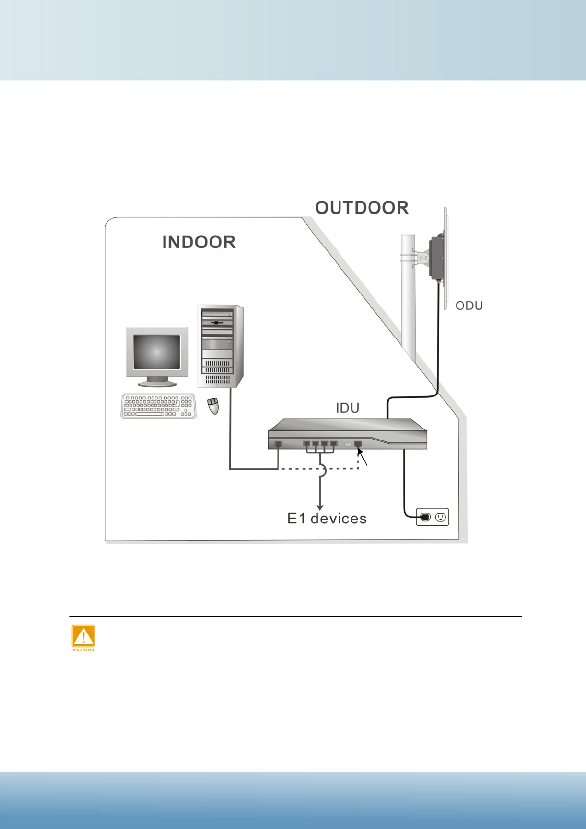
INSTALLTHECONVERGENTSYSTEM
This section show you how to mount the ODU, please read it carefully before you start to install the
hardware. Be safe and step by step to finish the hardware installation.
Hardware Installation Figure
The Outdoor unit can be damaged by incorrect power application. Read and follow
the installation instructions carefully before connecing the system to its power
source.
SFTP Cat.5 Cable
100~240V AC
Configure the ODU Configure the IDU
PDH / Ethernet Convergent System Quick Installation Guide
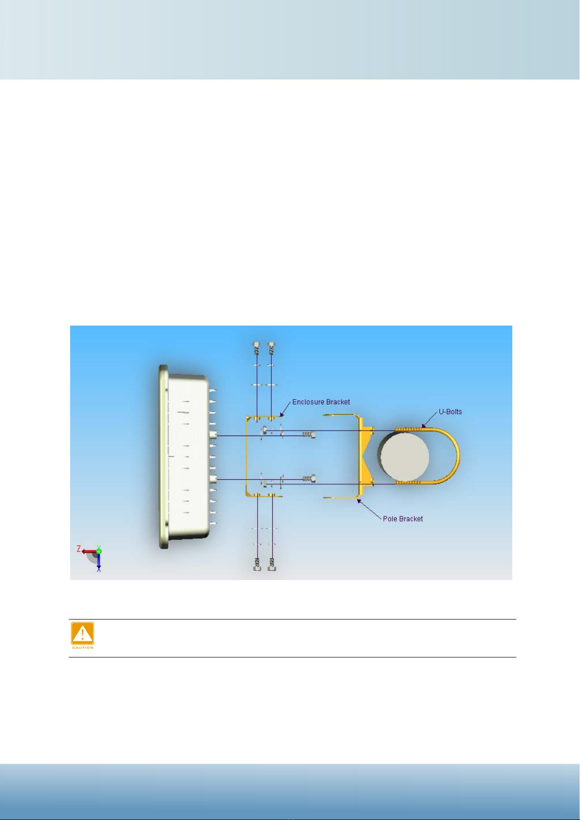
1. Mounting the Outdoor Radio
There are two parts of the Mounting kit:
¾Enclosure bracket -attached to the back of the outdoor radio.
¾Pole bracket -mounted on the pole or tower with the U-bolts.
Follow the next steps to mount the Outdoor radio on the pole.
i. Mount the enclosure bracket to the back of the outdoor radio.
ii. Mount the pole bracket to the pole with the U-bolts.
iii. Attach the radio with enclosure bracket to the pole bracket which was mounted on the pole
with the supplied screws and U-bolts.
iv. Tighten the all the screws, U-bolts, washers and nuts with hand tools.
Mounting Explosion Assembly Figure
Only trained and qualified personnel should be allowed to install, replace, or service
this equipment.
PDH / Ethernet Convergent System Quick Installation Guide
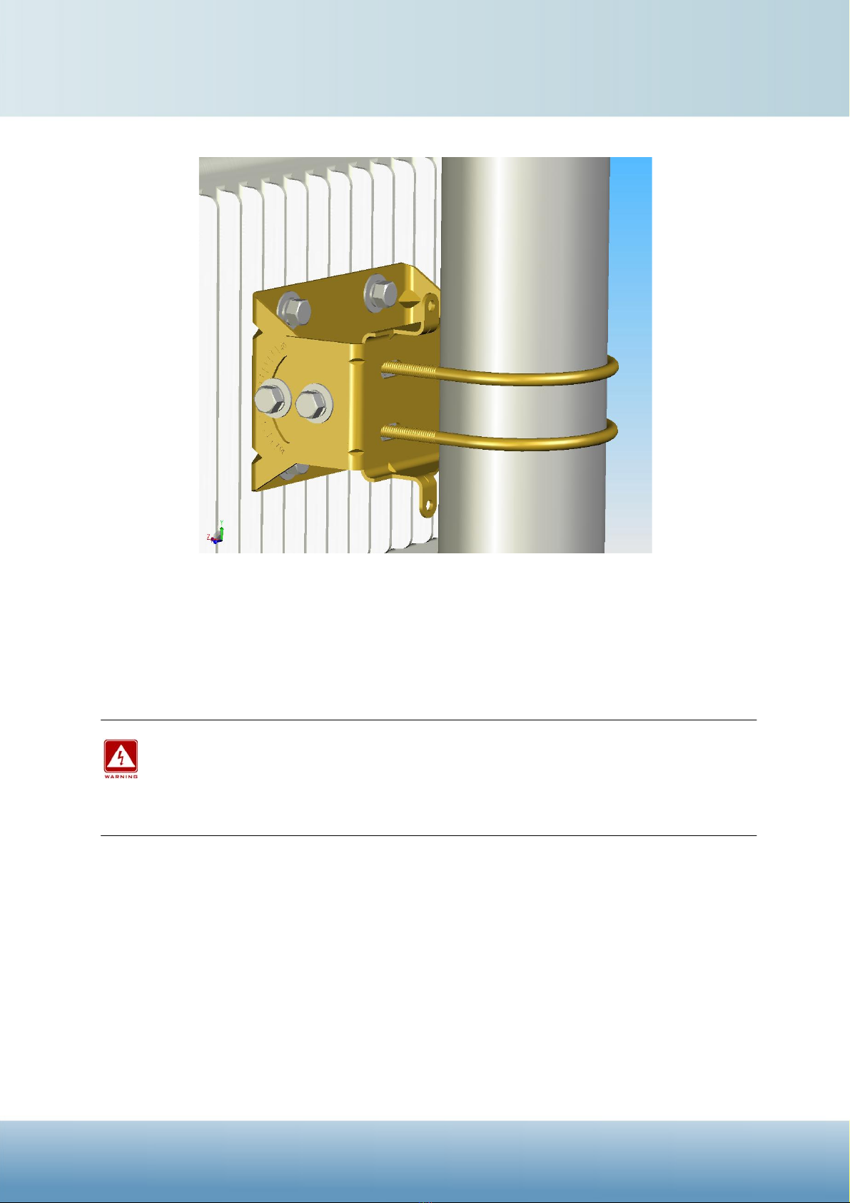
Mount the enclosure on the pole
2. Connect the ground stud
Connect the ground stud on the ODU enclosure with the ground wire.
This equipment must be grounded. Never defeat the ground conductor or operate the
equipment in the absence of a suitably installed ground conductor. Contact the
appropriate electrical inspection authority or an electrician if you are uncertain that
suitable grounding is available.
3. Connect the Ethernet Cable
The outdoor unit support 10/100M Ethernet connection. Attach your SFTP cat.5 Ethernet cable
with waterproof connector to the RJ-45 connector on the ODU enclosure. Then connect the other
end of the cable to the “WAN” port of the IDU.
PDH / Ethernet Convergent System Quick Installation Guide

Connect the SFTP cable to the ODU
Welding the shielding parts of the SFTP cable and the RJ-45 connector well to ensure
the performance of the system and avoid the moisture leak into the radio.
Weld the RJ-45 connector with the SFTP cable
Weld the SFTP cable as the above figure, make sure the welding parts NOT bigger
than the figure, or it will affect the function of waterproof RJ-45 connector.
4. Attached the antenna
You can attach the proper antenna to the N-type connector on the Outdoor Radio.
To meet regulatory restrictions, the radio and the external antenna must be
professionally installed.
Wind the water-resistant adhesive tape around the RJ-45 and N-type connector on
the outdoor radio as the last step of the hardware installtion procedures.
PDH / Ethernet Convergent System Quick Installation Guide
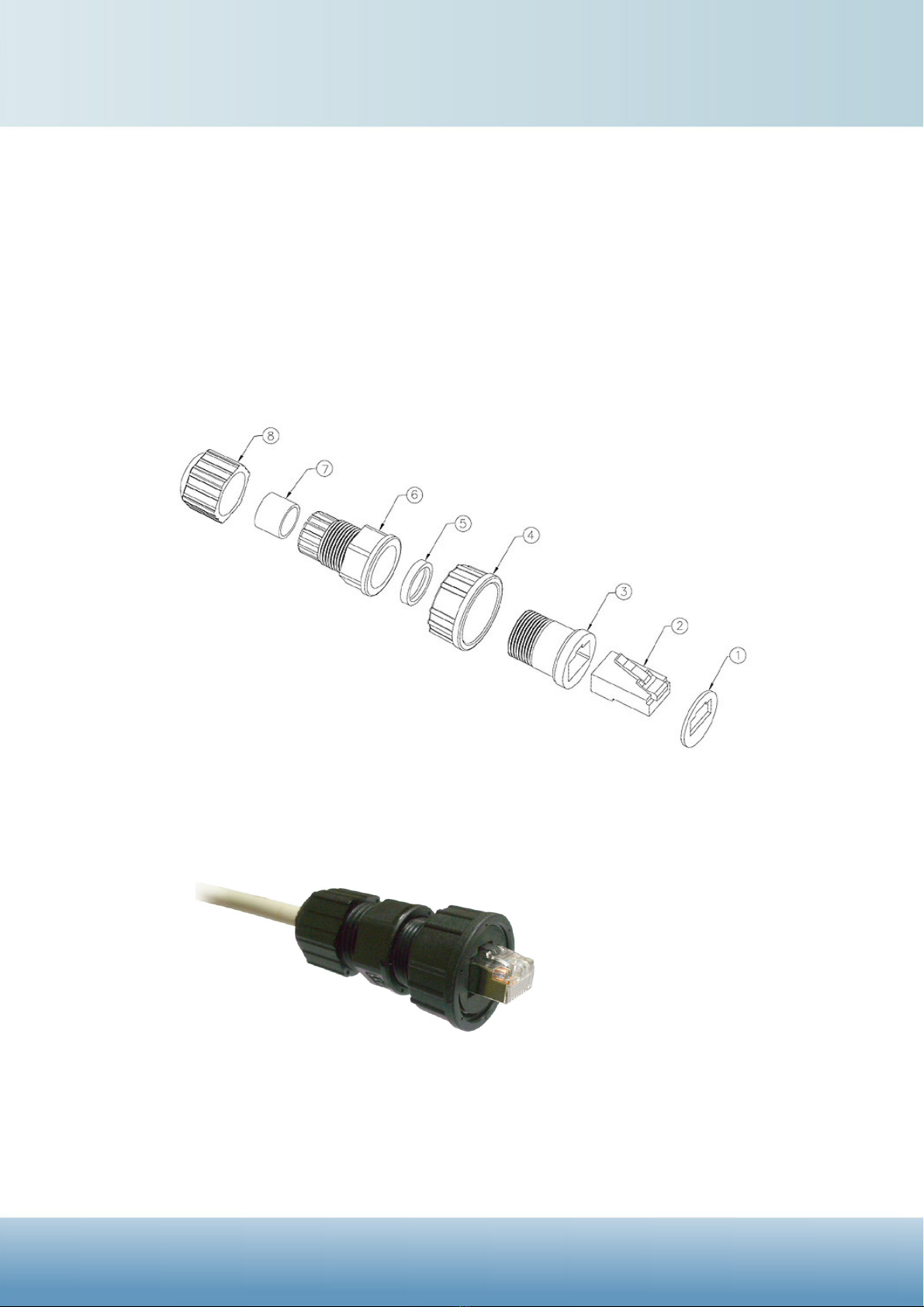
Appendix 1 -How to make the SFTP cable with waterproof
connectorbetweentheradioandPOEinjector.
The waterproof connector was formed by 8 pieces components as the following
exploded view:
Blow is the complete figure for your reference.
PDH / Ethernet Convergent System Quick Installation Guide
Table of contents


