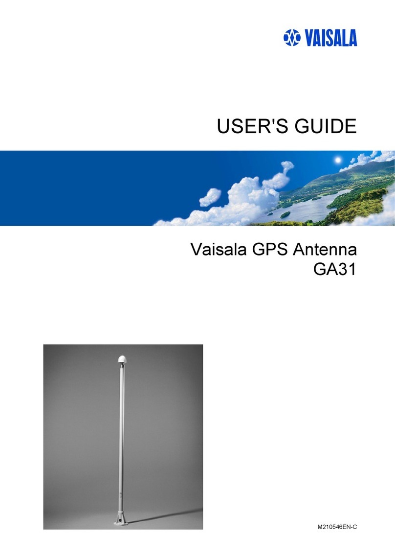
Vaisala CA31 User manual

Vaisala VLF Antenna
CA31
USER'S GUIDE
M210761EN-A
February 2006

PUBLISHED BY
Vaisala Oyj Phone (int.): +358 9 8949 1
P.O. Box 26 Fax: +358 9 8949 2227
FIN-00421 Helsinki
Finland
Visit our Internet pages at http://www.vaisala.com/
© Vaisala 2006
No part of this manual may be reproduced in any form or by any means,
electronic or mechanical (including photocopying), nor may its contents be
communicated to a third party without prior written permission of the copyright
holder.
The contents are subject to change without prior notice.
Please observe that this manual does not create any legally binding obligations for
Vaisala towards the customer or end user. All legally binding commitments and
agreements are included exclusively in the applicable supply contract or
Conditions of Sale.

________________________________________________________________________________
Table of Contents
CHAPTER 1
GENERAL INFORMATION............................................................................ 3
About This Manual ................................................................... 3
Contents of This Manual ....................................................... 3
General Safety Considerations ............................................. 4
Feedback............................................................................... 4
Product Related Safety Precautions ...................................... 5
ESD Protection ......................................................................... 5
Recycling .................................................................................. 6
Warranty.................................................................................... 6
CHAPTER 2
PRODUCT OVERVIEW.................................................................................. 7
Introduction to Vaisala VLF Antenna CA31........................... 7
CHAPTER 3
INSTALLATION AND OPERATION ............................................................ 11
Selecting Location ................................................................. 11
Lightning Protection ............................................................ 11
Mounting.............................................................................. 12
Antenna Amplifier .................................................................. 12
VLF Signals.................................................................... 13
Loran-C Signals ............................................................. 13
CHAPTER 4
MAINTENANCE ........................................................................................... 15
Periodic Maintenance ............................................................ 15
Parts List for Consumables .................................................. 15
CHAPTER 5
TROUBLESHOOTING ................................................................................. 17
Troubleshooting Procedure .................................................. 17
Technical Support.................................................................. 18
CHAPTER 6
TECHNICAL DATA ...................................................................................... 19
Specifications ......................................................................... 19
Parts List ................................................................................. 20
VAISALA ________________________________________________________________________ 1

User's Guide ______________________________________________________________________
This page intentionally left blank.
2 ___________________________________________________________________ M210761EN-A

Chapter 1 ________________________________________________________ General Information
CHAPTER 1
GENERAL INFORMATION
This chapter provides general notes for the manual and the product.
About This Manual
This manual provides information for installing, operating, and
maintaining Vaisala VLF Antenna CA31.
Contents of This Manual
This manual consists of the following chapters:
- Chapter 1, General Information, provides general notes for the
manual and the product.
- Chapter 2, Product Overview, introduces the features and system
structure of CA31.
- Chapter 3, Installation and Operation, provides you with
information about installing and operating this product.
- Chapter 4, Maintenance, describes the basic maintenance of the
product.
- Chapter 5, Troubleshooting, describes the troubleshooting
procedure and provides the contact information for technical
support.
- Chapter 6, Technical Data, provides the technical data of CA31.
VAISALA ________________________________________________________________________ 3

User's Guide ______________________________________________________________________
General Safety Considerations
Throughout the manual, important safety considerations are
highlighted as follows:
WARNING Warning alerts you to a serious hazard. If you do not read and follow
instructions very carefully at this point, there is a risk of injury or
even death.
CAUTION Caution warns you of a potential hazard. If you do not read and
follow instructions carefully at this point, the product could be
damaged or important data could be lost.
NOTE Note highlights important information on using the product.
Feedback
Vaisala Customer Documentation Team welcomes your comments
and suggestions on the quality and usefulness of this publication. If
you find errors or have other suggestions for improvement, please
indicate the chapter, section, and page number. You can send
4 ___________________________________________________________________ M210761EN-A

Chapter 1 ________________________________________________________ General Information
Product Related Safety Precautions
The Vaisala VLF Antenna CA31 delivered to you has been tested for
safety and approved as shipped from the factory. Note the following
precautions:
WARNING Ground the product, and verify outdoor installation grounding
periodically to minimize shock hazard.
CAUTION Do not modify the unit. Improper modification can damage the
product or lead to malfunction.
ESD Protection
Electrostatic Discharge (ESD) can cause immediate or latent damage
to electronic circuits. Vaisala products are adequately protected
against ESD for their intended use. However, it is possible to damage
the product by delivering electrostatic discharges when touching,
removing, or inserting any objects inside the equipment housing.
To make sure you are not delivering high static voltages yourself:
- Handle ESD sensitive components on a properly grounded and
protected ESD workbench. When this is not possible, ground
yourself to the equipment chassis before touching the boards.
Ground yourself with a wrist strap and a resistive connection cord.
When neither of the above is possible, touch a conductive part of
the equipment chassis with your other hand before touching the
boards.
- Always hold the boards by the edges and avoid touching the
component contacts.
VAISALA ________________________________________________________________________ 5

User's Guide ______________________________________________________________________
Recycling
Recycle all applicable material.
Dispose of batteries and the unit according to statutory regulations.
Do not dispose of with regular household refuse.
Warranty
For certain products Vaisala normally gives a limited one-year
warranty. Please observe that any such warranty may not be valid in
case of damage due to normal wear and tear, exceptional operating
conditions, negligent handling or installation, or unauthorized
modifications. Please see the applicable supply contract or Conditions
of Sale for details of the warranty for each product.
6 ___________________________________________________________________ M210761EN-A

Chapter 2 __________________________________________________________ Product Overview
CHAPTER 2
PRODUCT OVERVIEW
This chapter introduces the features and system structure of CA31.
Introduction to Vaisala VLF Antenna CA31
The CA31 is a free standing whip antenna for local monitoring and
synchronization of VLF or Loran-C networks. In addition, these
signals enable differential correction of measurements when used for
comparison with signals received from a radiosonde.
The antenna is used together with VLF Antenna Amplifier, covering
VLF and Loran-C frequency ranges. The VLF antenna amplifier is
designed for reception of VLF signals in the 10 to 30 kHz band and
Loran-C signals of 100 kHz band. The antenna amplifier is mounted
to the side of the antenna stand with clamps. The signal from the
antenna whip is connected via the antenna amplifier to the sounding
system.
The antenna has a steel and glass fiber construction. It consists of a
whip, extension and stand. The antenna contains also accessories.
Fixtures are made of passivated aluminum with paint finish. Insulators
are of weather and radiation resistant PVC. The maximum height of
the antenna construction is 6.0 meters.
The components and construction of the antenna system are show in
Figure 1 on page 8.
VAISALA ________________________________________________________________________ 7

User's Guide ______________________________________________________________________
0602-009
Figure 1 Vaisala VLF Antenna CA31 System
The antenna system consists of the following components (the
numbers refer to Figure 1):
1 = Whip antenna
2 = Extension stand
3 = Antenna stand
4 = Cable tie
5 = Gasket
6 = Antenna amplifier
7 = Cable from antenna to amplifier (16272ZZ)
8 = Cable from amplifier to a sounding system
8 ___________________________________________________________________ M210761EN-A

Chapter 2 __________________________________________________________ Product Overview
In addition to components illustrated in Figure 1, the antenna system
contains:
-Guying wire set
-Clamp 16238 CA (2 pcs)
-Grounding cable
The guying wire set is used for additional mounting strength. The
clamps attach the amplifier to the antenna stand. The grounding cable
is used for grounding of the antenna stand.
VAISALA ________________________________________________________________________ 9

User's Guide ______________________________________________________________________
This page intentionally left blank.
10 __________________________________________________________________ M210761EN-A

Chapter 3 ____________________________________________________Installation and Operation
CHAPTER 3
INSTALLATION AND OPERATION
This chapter provides you with information about installing and
operating this product.
Selecting Location
For best signal reception, install the antenna at an open place.
Avoid installation near high power transmitters. Ground the amplifier
body properly to ensure good signal reception.
Lightning Protection
The CA31 contains a discharge tube with 90 V threshold for lightning
protection. The tube is placed inside the CAA amplifier housing and
connected between the cable to the whip antenna and housing wall.
The tube protects the amplifier against high voltage surges on its
circuit board.
Proper grounding is also essential for lightning protection. Use the
grounding cable to ground the antenna stand.
VAISALA _______________________________________________________________________ 11

User's Guide ______________________________________________________________________
Mounting
Mount the antenna stand well and use the guying wire set in
installations where additional mounting strength is required.
The antenna stand base plate dimensions are given in Figure 2. The
drilling is 10.5 mm and the division of the holes is 80 mm by 80 mm.
0602-010
Figure 2 CA31 Stand Base Plate Dimensions
Antenna Amplifier
The navigation signal comes from the receiving whip antenna to the
connector X1. F1 is an overvoltage protection.
Internally the signal path is divided to two branches: VLF (15 kHz ...
30 kHz) signals go to the branch provided with R3. Loran-C signals (~
100 kHz) go to the branch provided with the tuned series circuit
L5/C14. Connector X2 is a common output for both signals to the
sounding equipment.
12 __________________________________________________________________ M210761EN-A

Chapter 3 ____________________________________________________Installation and Operation
VLF Signals
In the VLF branch, the diodes V1 and V2 after the R3 function as
overvoltage protection. After the V1 and V2 diodes, there is a low-
pass filter. The bandpass edge of the low-pass filter is at
approximately 30 kHz.
After the filter, there is a high-impedance FET amplifier V3 and V4
(2N 3819).
V5 operates as a voltage amplifier and impedance matching device.
L3 (2.2 mH) prevents attenuation of Loran-C signals, since both
amplifiers have a common output terminal X2.
Loran-C Signals
In the Loran-C amplifier branch there are voltage limiting diodes V6
and V7. C10/L6 is tuned for 100 kHz.
V9 (2N 3904) is a voltage amplifier. After V9, there is a gain control
potentiometer R10.
A1 is a linear circuit amplifier, the output of which is connected to the
transformer C21/L4 tuned for 100 kHz. The amplified Loran-C signal
goes to the output terminal X2 via C8.
VAISALA _______________________________________________________________________ 13

User's Guide ______________________________________________________________________
This page intentionally left blank.
14 __________________________________________________________________ M210761EN-A

Chapter 4 ______________________________________________________________ Maintenance
CHAPTER 4
MAINTENANCE
This chapter describes the basic maintenance of the product.
Periodic Maintenance
A nearby stroke of lightning can cause a burn out of the overvoltage
protection F1 in the antenna amplifier. Replace the overvoltage
protection F1, if burned out. Generally, the protection F1 is short-
circuited in this occasion.
Also, if the resistor R3 is burned, replace it with a new one.
If the damage cannot be repaired with these measures, replace the
entire circuit board.
Parts List for Consumables
Table 1 CA31 Available Spare Parts
Spare Part Order Code
Antenna amplifier CAA21 15633
Cable to a sounding system DRW217931 (33 m)
DRW221691 (3 m)
16190 (33 m for old systems)
VAISALA _______________________________________________________________________ 15

User's Guide ______________________________________________________________________
This page intentionally left blank.
16 __________________________________________________________________ M210761EN-A

Chapter 5 ___________________________________________________________ Troubleshooting
CHAPTER 5
TROUBLESHOOTING
This chapter describes the troubleshooting procedure and provides the
contact information for technical support.
Troubleshooting Procedure
When troubleshooting the product, write a problem report consisting
of the following issues:
- What failed (what worked / did not work)?
- Where did it fail (location and environment)?
- When did it fail (date, immediately / after a while / periodically /
randomly)?
- What was connected to the product and to which connectors?
- Input power source type, voltage and list of other items (lighting,
heaters, motors etc.) that were connected to the same power output.
- What was done when the failure was noticed?
VAISALA _______________________________________________________________________ 17

User's Guide ______________________________________________________________________
Technical Support
For technical questions, contact the Vaisala technical support:
E-mail [email protected]
Fax +358 9 8949 2790
If the product needs repair, please follow the instructions below to
speed up the process and to avoid extra costs to you.
1. Read the warranty information.
2. Contact Vaisala technical support via e-mail or fax and request
for RMA (Return Material Authorization) and shipping
instructions.
3. Proceed as instructed by Vaisala technical support.
NOTE RMA must always be requested from Vaisala technical support
before returning any faulty material.
18 __________________________________________________________________ M210761EN-A
Table of contents
Other Vaisala Antenna manuals
Popular Antenna manuals by other brands

Winegard
Winegard Pathway X2 Faq

Repotec
Repotec RPIPA1000 installation guide

Pro Antennas
Pro Antennas Dual Beam Pro Assembly instructions

KVH Industries
KVH Industries TracPhone V7 Replacement instructions

BFT
BFT Passy Installation and user manual

Panorama Antennas
Panorama Antennas SiSo CMSLP-038-4 installation instructions