ConventionsConventions
ConventionsConventions
Conventions
WW
WW
WARNINGS –ARNINGS –
ARNINGS –ARNINGS –
ARNINGS – TT
TT
To help ao help a
o help ao help a
o help avoid personal injurvoid personal injur
void personal injurvoid personal injur
void personal injuryy
yy
y
Important Notes/Cautions – from the factorImportant Notes/Cautions – from the factor
Important Notes/Cautions – from the factorImportant Notes/Cautions – from the factor
Important Notes/Cautions – from the factoryy
yy
y
SanitaSanita
SanitaSanita
Sanitation Requirementstion Requirements
tion Requirementstion Requirements
tion Requirements
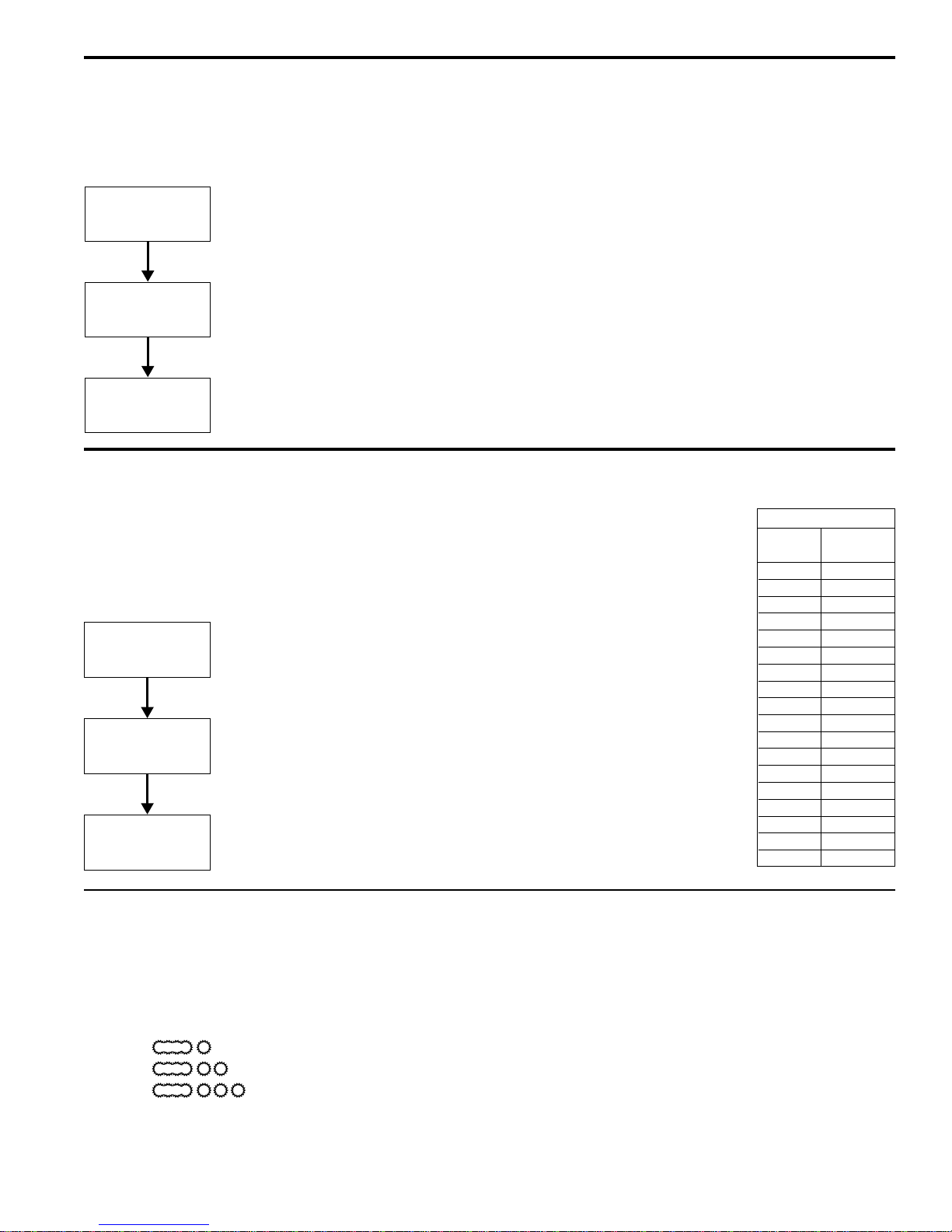
1. Connect a water line from your facility to the 1/4” flare water inlet fitting of the valve, behind the machine. Water volume
going to the machine should be stable. Use tubing sized sufficiently to provide a minimum flow rate of one gallon per minute.
2. Plug the power cord into an electrical outlet rated at 20A.
3. Switch on the toggle switch, behind the unit, that runs power to the components in the machine. The lights (display window
and row of buttons) on the front door will activate and the heating tank will start to fill.
4. Water in the heating tank will require about 30 minutes to reach operating temperature (factory setting of 190°F). At this time
the READY LED will light.
5. Remove and fill the canisters with soluble coffee mixes.
1
Soluble Dispensing System Instructions
FOR THE LATEST SPECIFICATIONS AND INFORMATION GO TO
WWW.WILBURCURTIS.COM
This appliance is designed for commercial use. Any servicing other than cleaning and maintenance should be performed by an
authorized Wilbur Curtis service center.
• Do NOT immerse the unit in water or any other liquid
• To reduce the risk of fire or electric shock, do NOT open top panel. No user serviceable parts inside. Repair should be done
only by authorized service personnel.
• Keep hands and other items away from hot parts of unit during operation.
• Never clean with scouring powders or harsh implements.
YY
YY
Your Curtis Café System is Four Curtis Café System is F
our Curtis Café System is Four Curtis Café System is F
our Curtis Café System is Factoractor
actoractor
actory Pre-Set and Ready Pre-Set and Read
y Pre-Set and Ready Pre-Set and Read
y Pre-Set and Ready to Go… Right from the Carton.y to Go… Right from the Carton.
y to Go… Right from the Carton.y to Go… Right from the Carton.
y to Go… Right from the Carton.
Following are the Factory Settings for your Soluble Delivery System:
••
••
• TT
TT
Tankank
ankank
ank TT
TT
Temperaempera
emperaempera
emperature = 190°Fture = 190°F
ture = 190°Fture = 190°F
ture = 190°F
• Fla• Fla
• Fla• Fla
• Flavor Controls= Set avor Controls= Set a
vor Controls= Set avor Controls= Set a
vor Controls= Set at 50%t 50%
t 50%t 50%
t 50%
• Dispensing Mode Set for Manual Dispensing• Dispensing Mode Set for Manual Dispensing
• Dispensing Mode Set for Manual Dispensing• Dispensing Mode Set for Manual Dispensing
• Dispensing Mode Set for Manual Dispensing
Generally there will never be a reason to change your SD2 programming. However, should you need to make slight adjustments to
meet your dispensing needs, programming instructions are provided later in this manual.
System Requirements:
••
••
• WW
WW
Waa
aa
ater Sourceter Source
ter Sourceter Source
ter Source 20 – 90 PSI (Minimum Flow Rate of 1 GPM)
• Electrical:• Electrical:
• Electrical:• Electrical:
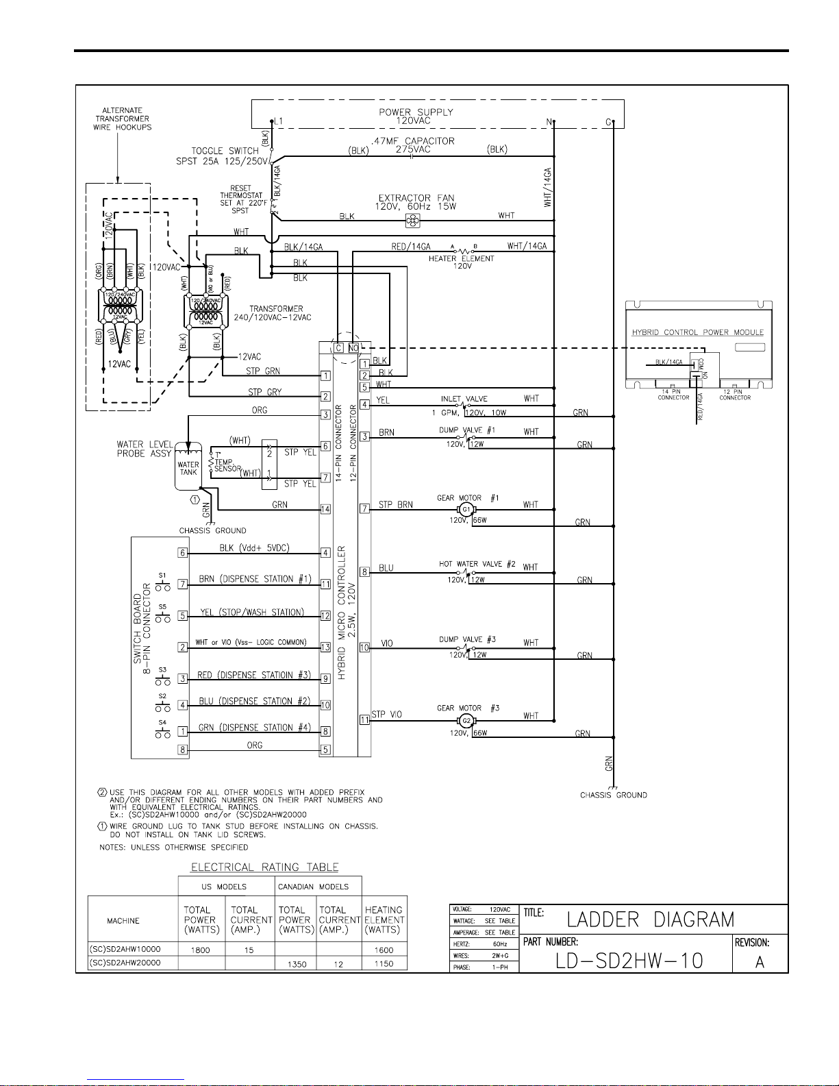
• Electrical: See attached schematic for standard model or visit www.wilburcurtis.com for your model.
Equipment to be installed to comply with applicable federal, state, or local plumbing/electrical codes having jurisdiction.
SETUP STEPSSETUP STEPS
SETUP STEPSSETUP STEPS
SETUP STEPS
The unit should be level (left to right and front to back), located on a solid counter top. Connect a water line from the water filter to the
brewer. NOTE: Some type of water filtration device must be used to maintain a trouble-free operation. (In areas with extremely hard
water, we suggest that a sedimentary and taste & odor filter be installed.) This will prolong the life of your dispensing system and
enhance coffee quality.
The National Sanitation Foundation requires the following water connection:
1. A quick disconnect or additional coiled tubing (at least 2x the depth of the unit) so that the machine can be moved for
cleaning underneath.
2. In some areas an approved backflow prevention device may be required between the brewer and the water supply.
WILBUR CURTIS COMPANY, INC.
FILL CANISTERS DAILFILL CANISTERS DAIL
FILL CANISTERS DAILFILL CANISTERS DAIL
FILL CANISTERS DAILYY
YY
Y
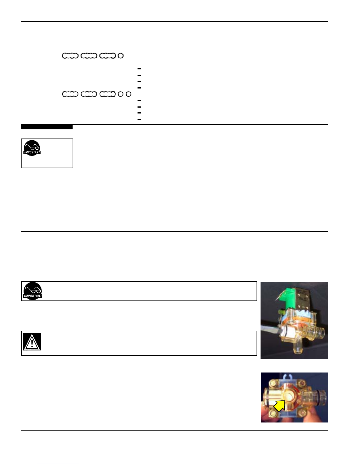
1. Open the front door to access the coffee canisters.
2. The canisters must be removed from the unit for filling. Turn the product delivery elbows upward.
3. Reposition the canisters on the machine, turning the product delivery elbows downward and aligning the gear socket with the
motor shaft.
Important Safeguards/Conventions
CAUTION:CAUTION:
CAUTION:CAUTION:
CAUTION: DO NOT
connect this unit to hot
water. The inlet valve is
not rated for hot water.
CAUTION:CAUTION:
CAUTION:CAUTION:
CAUTION: Please use
this setup procedure
before attempting to use
this appliance. Failure to follow the
instructions can result in injury or
the voiding of the warranty.
WILBUR CURTIS COMPANY
Montebello, CA 90640
ISO 9001 REGISTERED
WARNING HOT LIQUID,
Scalding may occur.
Avoid splashing.
Models Included
◆
SD2
FIND OUT MORE
ON THE WEB
WWW.WILBURCURTIS.COM
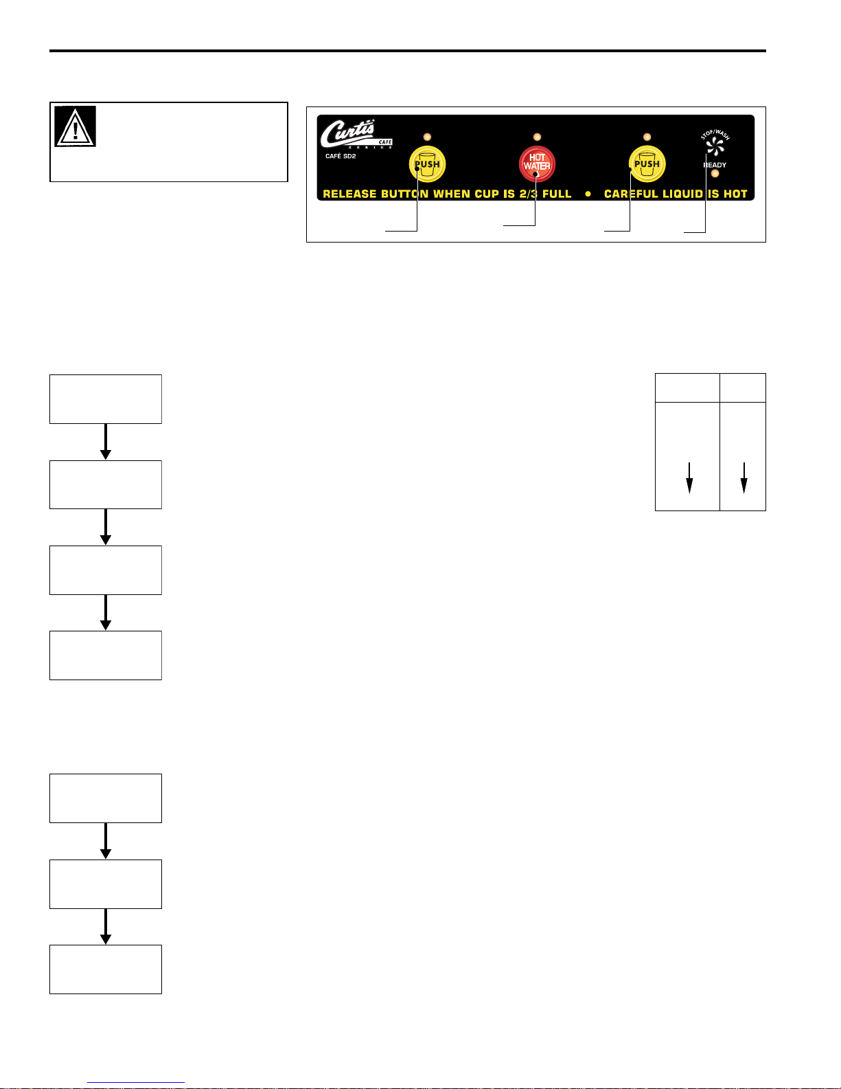
OPERAOPERA
OPERAOPERA
OPERATION INSTRTION INSTR
TION INSTRTION INSTR
TION INSTRUCTIONSUCTIONS
UCTIONSUCTIONS
UCTIONS
1. Select one of the coffee dispense buttons.
2. Place your cup beneath the spout of the desired coffee flavor.
2. Push and hold the dispensing button for this coffee selection.
3. Release the button when the cup is 2/3 full2/3 full
2/3 full2/3 full
2/3 full.