manuals.online logo
Brands
  1. Home
  2. •
  3. Brands
  4. •
  5. Williams Sound
  6. •
  7. Stereo System
  8. •
  9. Williams Sound IR M1 User manual

Williams Sound IR M1 User manual

IR +
IR M1
QUICK START GUIDE
Setup Overview
1. Place your IR M1 Control Center in a location where you
will be able to place the IR E4 emitters connected to
the IR M1 in the listening area.
2. Plug in the power supply to the power connection on
the IR M1.
3. Connect an audio source to the Line/Mic In port for the
channel(s) you’d like to use.
4. Connect an Ethernet cable to the ETHERNET port.
Connect the other end of the Ethernet cable to a
multicast-enabled router with an internet connection.
5. If using IR A4 emitter arrays, connect the provided IR
A4 power supplies to the IR A4s. Connect IR E4s to the
ports on the front of the IR A4 with CAT5e cable.*
6. Connect one or more IR E4 emitters or IR A4 emitter
arrays to the Output to Emitter ports on the back of
the IR M1 with a CAT5e cable. No additional power is
required for an IR E4.
7. Place the IR E4 emitters in the listening area so that
they are above the audience without interference.
Multiple IR E4 emitters should be placed apart from one
another to expand the coverage area.
INPUT
ARRAY (IR A4)
EMITTER (IR E4)
OUTPUT
EMITTER (IR E4)
Connected to
Front Panel
of IR A4
48VDC
ETHERNET
STREAMING
AUDIOOUT
Output to Emitters
1 2 3 4
CONTROL CENTER
(IR M1)
-OR-
8. Turn on the IR M1.
9. On the front panel of the IR M1, an IP address should be
displayed. If you do not see an IP address, check your
network connection. Write down the IP address and go
to a computer that is on the same network as the IR+.
10. In Chrome or Edge, type the IP address into the URL
bar. A webpage for the IR+ system will load. The default
username is admin and the default password is admin.
11. Click the Settings tab. Configure each IR E4 emitter
for the channels it will broadcast, and the IR Band the
system should emit.
12. Click the Audio tab and set the audio device type and
desired settings for each audio channel.
13. Change other settings as desired.
14. While the audio source is playing sound, take an IR
Receiver to the front panel of the IR M1 Control Center.
The front panel of the IR M1 has two small IR emitters
for testing, one for each audio channel.
Tune the receiver to the IR Baseband channel the audio is
playing on to ensure all your settings sound correct. This
audio will match the audio from the IR E4 emitters.
15. For more advanced system setup, please see the full
user manual.
Configuration Details
The IR M1 Control Center is the key component to the IR+
System. Audio devices, IR E4 emitters, and IR A4 emitter
arrays can be connected to the IR M1. Any configuration to
the IR+ system is done through the IR M1, which passes the
configuration setting onto other IR+ devices.
Determine Coverage Area and Location
The IR M1 Control Center is usually located with the sound
system amplifier or mixer for easy access to an audio input
signal. For portable systems, the IR M1 Control Center can
be placed near the IR E4 emitter(s) or in another convenient
location. The IR E4 emitters will need to be placed to get
the most coverage area.
When using the IR+ system in single-channel mode with the
RX22-4 receiver, the system coverage area will cover up
to 18,000 sq. ft. (1,673 sq. m.) per IR E4 emitter. The IR E4
will use full power, single channel mode by default. Single
channel or dual channel mode, and IR E4 emitter output
power, can be selected using the system webpage.
The coverage area may be aected by direct/indirect
sunlight, reflections on walls and room construction.
Reflections of the infrared light from walls, ceilings, and
floors may change these patterns.
Important: Remember to point the IR E4 emitter towards
the listening audience.
Remember: Most objects block infrared light. The
transmitter cannot be concealed behind walls, glass,
curtains, etc.
Do not paint the front face of the IR E4.
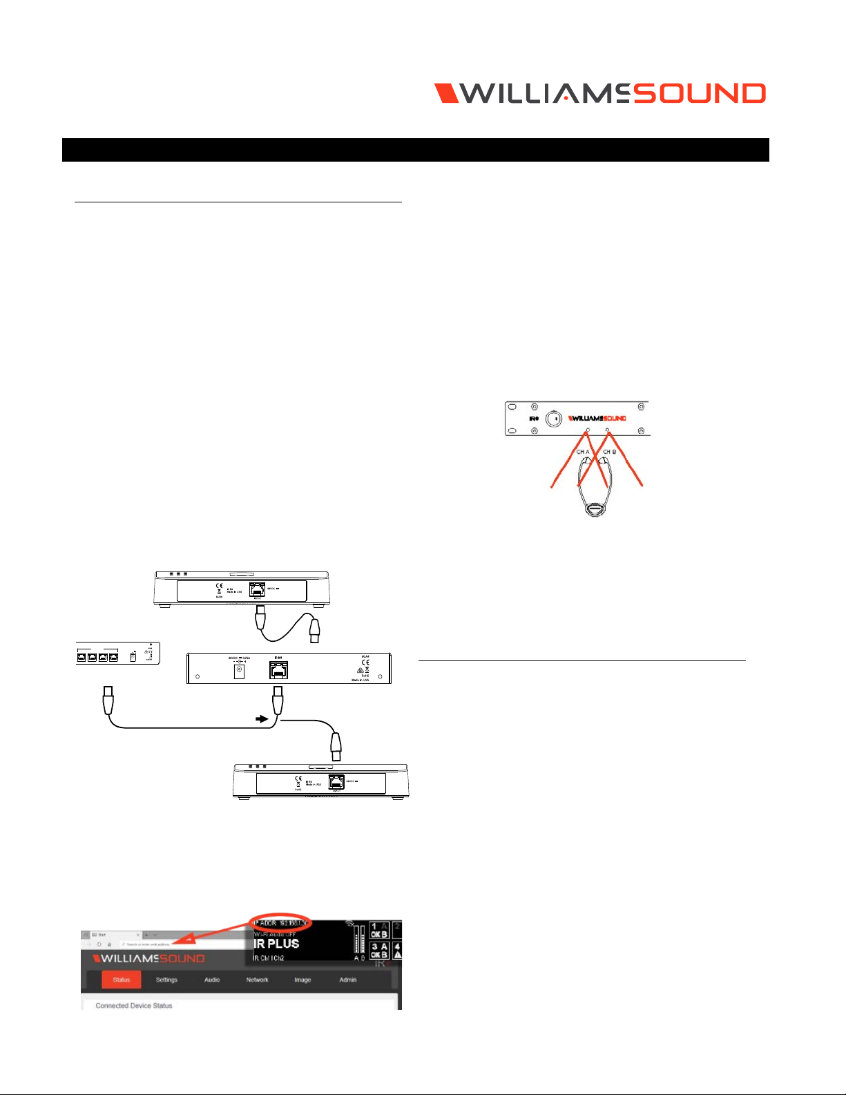
Network Cable Connection
The Ethernet port can be used to connect the IR M1 to a
local network. A network connection is required to access
the IR M1 webpage. The webpage is needed to configure
some device settings after the system is set up.
An Ethernet connection alone will not allow the Wi-Fi
broadcast features to work; a Wi-Fi connection must be
available on the network. A network connection is not
required for broadcasting over infrared.
Once a connection has been established, an IP address
will automatically be assigned to the IR M1. Device settings
can then be set via the website, including changing any
network settings.
NOTE: Most settings need to be set BEFORE connecting
audio sources.
Connections to Emitters and Emitter arrays
The IR M1 can directly drive four IR E4 emitters without the
use of an IR A4 emitter array. Up to 4 IR A4 emitter arrays
can be directly connected to the IR M1. Up to 16 IR E4
emitters can be connected with the use of IR A4 emitter
arrays.
The outputs MUST NOT be split with CAT5e splitters.
Determine the length of CAT5e cable needed to reach from
the IR E4 Emitter or IR A4 Emitter array to the IR M1 Control
Center unit. For more information on cabling, please read the
full user manual.
Audio Source Connections
The IR+ transmitter will accept the following audio sources:
1. Balanced Microphone with or without 12 volt phantom
power (DIN 45596) on a 3-pin (XLR) connector.
2. Balanced/Unbalanced microphone with selectable
+12VDC phantom power on 1/4 inch (TRS) jack.
3. Balanced/Unbalanced Line on a 3-pin (XLR) connector.
4. Balanced/Unbalanced Line on 1/4 inch (TRS) jack.
5. Dante on an RJ-45 jack (optional).
WARNING:
The IR+ is not designed to accept 70 volt speaker
signals! This may result in damage to your system.
The sound source should come directly from the system mixer
or digital source as a low-level or unprocessed signal.
For specific audio wiring information, please read the full
user manual.
Network Configuration
An IP address will be automatically assigned to the IR M1
once an Ethernet cable has been connected to the device
and network connection has been established. Additional
configuration would need to be made through the website.
Website for Device Settings
The IR M1 provides a website to manage the device settings.
This website can be accessed over either a hardwired or
wireless network connection with the Chrome browser.
Changes take eect when applied or saved. Any updates
made through the front panel will show up on the website
once the current page has been navigated away from,
either by refreshing the page or going to a new page.
1. Open Chrome.
2. In the address bar of the browser, type in the IP
address of the IR M1 and hit Enter.
3. You should see the Login Page of the IR M1 and can
adjust settings from here.
4. For more information, please read the full user manual.
For Additional Information
This manual is a quick start guide for getting your IR+
system up-and-running. It covers basic cable connection
and setup. Most features and customization options are not
documented in this manual.
For additional information, feature instructions, warranty
information, and more, please download the full user
manual from the IR+ product pages on Williams AV’s
website.
*Note: The IR A4 is not rated for use in plenum spaces and
will need to be installed in a plenum box for use in
such areas.
info@williamsav.com / www.williamsav.com
800-843-3544 / INTL: +1-952-943-2252
© 2020, Williams AV, LLC MAN 274B

Other Williams Sound Stereo System manuals

Williams Sound SoundPlus Assembly instructions

Williams Sound

Williams Sound SoundPlus Assembly instructions

Williams Sound SoundPlus MOD 232 Assembly instructions

Williams Sound

Williams Sound SoundPlus MOD 232 Assembly instructions

Williams Sound Wireless User manual

Williams Sound

Williams Sound Wireless User manual

Williams Sound Hearing Helper PFM 300 RCH User manual

Williams Sound

Williams Sound Hearing Helper PFM 300 RCH User manual

Popular Stereo System manuals by other brands

Oregon Scientific HMS388 user manual

Oregon Scientific

Oregon Scientific HMS388 user manual

Hogtunes G4 SG KIT-RM installation manual

Hogtunes

Hogtunes G4 SG KIT-RM installation manual

JVC XT-G70RBK Service manual

JVC

JVC XT-G70RBK Service manual

Roberts STREAM 83I user manual

Roberts

Roberts STREAM 83I user manual

Sony CMT-EX5 - Micro Hi Fi Component System operating instructions

Sony

Sony CMT-EX5 - Micro Hi Fi Component System operating instructions

JVC CA-UXZ7MD instructions

JVC

JVC CA-UXZ7MD instructions

Philips DCM278/93 user manual

Philips

Philips DCM278/93 user manual

Kenwood RXD-M31 Service manual

Kenwood

Kenwood RXD-M31 Service manual

camry CR 1173 user manual

camry

camry CR 1173 user manual

Hyundai H-PS1206 instruction manual

Hyundai

Hyundai H-PS1206 instruction manual

Zenith FFH-986A Installation and operating guide

Zenith

Zenith FFH-986A Installation and operating guide

Sanyo DC-SLIM1600 Service manual

Sanyo

Sanyo DC-SLIM1600 Service manual

Vivax CD-103 Instruction manuals

Vivax

Vivax CD-103 Instruction manuals

Kenwood RXD-M32V Service manual

Kenwood

Kenwood RXD-M32V Service manual

Sony HCD-VX33 Service manual

Sony

Sony HCD-VX33 Service manual

Fender VOCAL SOUND SYSTEM WITH REVERB PA 100 owner's manual

Fender

Fender VOCAL SOUND SYSTEM WITH REVERB PA 100 owner's manual

CDT Audio SQA-2130 owner's manual

CDT Audio

CDT Audio SQA-2130 owner's manual

Panasonic SA-AK633P Service manual

Panasonic

Panasonic SA-AK633P Service manual

manuals.online logo
manuals.online logoBrands
  • About & Mission
  • Contact us
  • Privacy Policy
  • Terms and Conditions

Copyright 2025 Manuals.Online. All Rights Reserved.